EP0656975B1 - Bagger mit einer schaufel und einer der schaufel zugeordneten, hydraulisch betätigbaren greifplatte - Google Patents
Bagger mit einer schaufel und einer der schaufel zugeordneten, hydraulisch betätigbaren greifplatte Download PDFInfo
- Publication number
- EP0656975B1 EP0656975B1 EP94919673A EP94919673A EP0656975B1 EP 0656975 B1 EP0656975 B1 EP 0656975B1 EP 94919673 A EP94919673 A EP 94919673A EP 94919673 A EP94919673 A EP 94919673A EP 0656975 B1 EP0656975 B1 EP 0656975B1
- Authority
- EP
- European Patent Office
- Prior art keywords
- shovel
- grab plate
- bucket
- swivel frame
- piston
- Prior art date
- Legal status (The legal status is an assumption and is not a legal conclusion. Google has not performed a legal analysis and makes no representation as to the accuracy of the status listed.)
- Expired - Lifetime
Links
- 238000010276 construction Methods 0.000 description 2
- 230000008878 coupling Effects 0.000 description 1
- 238000010168 coupling process Methods 0.000 description 1
- 238000005859 coupling reaction Methods 0.000 description 1
- 239000012634 fragment Substances 0.000 description 1
- 238000000034 method Methods 0.000 description 1
- 239000011150 reinforced concrete Substances 0.000 description 1
Images
Classifications
-
- E—FIXED CONSTRUCTIONS
- E02—HYDRAULIC ENGINEERING; FOUNDATIONS; SOIL SHIFTING
- E02F—DREDGING; SOIL-SHIFTING
- E02F3/00—Dredgers; Soil-shifting machines
- E02F3/04—Dredgers; Soil-shifting machines mechanically-driven
- E02F3/28—Dredgers; Soil-shifting machines mechanically-driven with digging tools mounted on a dipper- or bucket-arm, i.e. there is either one arm or a pair of arms, e.g. dippers, buckets
- E02F3/36—Component parts
- E02F3/40—Dippers; Buckets ; Grab devices, e.g. manufacturing processes for buckets, form, geometry or material of buckets
- E02F3/402—Dippers; Buckets ; Grab devices, e.g. manufacturing processes for buckets, form, geometry or material of buckets with means for facilitating the loading thereof, e.g. conveyors
- E02F3/404—Dippers; Buckets ; Grab devices, e.g. manufacturing processes for buckets, form, geometry or material of buckets with means for facilitating the loading thereof, e.g. conveyors comprising two parts movable relative to each other, e.g. for gripping
Definitions
- the invention is directed to an excavator in the preamble of claim 1 specified genus, as is WO-A-89/12145.
- the present invention is directed to further training an excavator bucket, especially a bucket. It there are cases where there is an operator of such an excavator would be useful e.g. with a To be able to grasp the shovel, for example to handle large fragments to be able to transport, building pieces, larger timber or Reinforced concrete beams u. the like
- a spoon known with two pivotally arranged thereon, over separate hydraulic drives movable gripper elements.
- the bucket is in the usual way on the Excavator boom attached.
- DE-A-30 04 834 also shows an excavator bucket attached to the excavator boom or arm arranged pivotably in a conventional manner is, with a counter-gripping element on the auxiliary hydraulic cylinder is articulated such that when the spoon is pivoted in the closed position, the counter element also in the closed position is effected, the opening movement takes place in reverse.
- WO 89/12145 again shows one bucket linked to the excavator boom via two support disks, the support disks having hydraulic cylinders, with which gripping tines can be moved.
- the object of the invention is to provide a solution with which increases the mobility of the spoon and at the same time the individual closing and opening of a gripping tool is made possible.
- a practical design of the excavator bucket exists thereby in that the gripping plate with two pairs of each Backplate is provided, the at the top Swivel fitting and the fastening fitting at the lower end for the piston / cylinder unit and take one Form part of the carrier swivel arm.
- Another possible embodiment of the invention exists in making the gripping plate itself like a spoon.
- the invention also provides that the tool with a Rotating and / or swiveling device is provided for rotation or swiveling the bucket with gripping plate in one from the swivel plane of the bucket or the gripping plate deviating level.
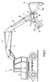
- the excavator generally designated 1, on its special Design does not matter here, has a working or basic boom 2 on which a dipper stick 3 pivotable via a hydraulic piston / cylinder unit 4 is stored.
- the dipper stick is pivoted at its free end a carrier swivel frame 5, the other swivel 6th via a coupling piece 7 and a rocker 8 with a Spoon cylinder 9 is operatively connected.
- a swivel 10 Blade 11 On the support and swivel frame is a swivel 10 Blade 11 arranged beyond the pivot joint 10 pointing a swing arm 12, at the free End 13 another hydraulic piston / cylinder unit, called gripper cylinder 14 for short, attacks.
- the gripper cylinder 14 is pivoted at the lower end 15 articulated by back plate 16, the back plate Represent 16 elements of the support and swivel frame 5.
- Gripper plate 17 which in turn in the example shown is spoon-like at least in some areas.
- the blade is relative to the gripper plate 17 brought into the open position, e.g. in the position of Fig. 1.
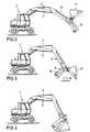
- the dipperstick is hydraulic Piston / cylinder unit pivoted, for example the basic boom 2 in the assumed position can stay.
- the gripper cylinder 14 is actuated, such that the scoop 11 is on the gripper plate 17th too moved.
- the closed position can also be supported or corrected with a spoon cylinder 9.
- the hydraulic circuit and control of the various Working methods and work movements can be designed that all work movements are carried out separately or but also in such a way that movements are superimposed.
- the advantage is that the independent movements with the typical gripper working movement at a shorter distance from the pivot point on the swivel arm to the blade edge are present, resulting in higher crushing and lifting capacities leads.
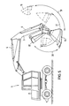
- Fig. 5 the spoon movement is shown, whereby by means Double arrows 19 to 21 the respective pivoting options are shown.
- Double arrow 21 is torn out shown in which swivel range a spoon can move according to the prior art. Is recognizable both the opening area and the closing area of the Blade 11 with the device according to the invention clearly larger, as shown by the double arrows 19 and 20.
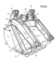
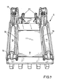
- the excavator handling tool is simplified in perspective shown with supervision of the carrier swivel frame 5 with the piston / cylinder units arranged there 14 and the one holding it at the articulation point 15 Back plate 16, which is part of the swing frame 5th form. 6 also shows how the spoon or the bucket 11 with its swivel arms 12 on the swivel joint 10 of the back plate 16 is arranged.
- both the gripper plate 17 and the shovel 11 be provided with recesses pointing inwards, in order, for example, to do this when using the corresponding device frequently occurs, round elements, such as pipes or beams, easier to grip.
- the arrangement of the hydraulic Piston / cylinder units 14 otherwise of the same construction are reversed, i.e. these can on be arranged on the back of the blade, the then Swivel boom 12 are attached to the swivel frame 5.
Landscapes
- Engineering & Computer Science (AREA)
- Mechanical Engineering (AREA)
- Mining & Mineral Resources (AREA)
- Civil Engineering (AREA)
- General Engineering & Computer Science (AREA)
- Structural Engineering (AREA)
- Shovels (AREA)
- Load-Engaging Elements For Cranes (AREA)
Description
- Fig. 1
- die vereinfachte prinzipielle Seitenansicht eines Baggers mit dem erfindungsgemäßen Handhabungswerkzeug,
- Fig. 2 bis 4
- das Handhabungswerkzeug in unterschiedlichen Arbeitspositionen,
- Fig. 5
- in vergrößerter Darstellung einen Bagger mit dem Handhabungswerkzeug in unterschiedlichen Löffel- bzw. Schaufelpositionen,
- Fig. 6
- eine vereinfachte räumliche Darstellung des Handhabungswerkzeuges sowie in
- Fig. 7
- eine Seitenaufsicht auf den erfindungsgemäßen Träger-Schwenkrahmen.
Claims (4)
- Bagger (1) mit einer Schaufel (11) und einer der Schaufel zugeordneten, hydraulisch betätigten Greifplatte (17), wobei an der Greifplatte ein Trägerschwenkrahmen (5) vorgesehen ist und der Trägerschwenkrahmen (5) drehgelenkig am Löffelstiel (3) des Baggers und wirkmäßig an einem Betätigungszylinder (4) angeordnet ist, wobei die Schaufel (11) als Tieflöffel und die Greifplatte (17) selbst löffelartig ausgebildet ist,
dadurch gekennzeichnet,daß die Schaufel (11) drehgelenkig an der Greifplatte (17) gelagert und über wenigstens eine am Träger-Schwenkrahmen (5) angeordnete Kolben-/Zylindereinheit (14) gegenüber der Greifplatte in Öffnungs- bzw. Schließstellung bewegbar ist unddaß die Schaufel (11) am oberen Rücken-Außenrandbereich mit wenigstens einem Schwenkausleger (12) versehen ist, an dessen freien Enden die hydraulische Kolben-/Zylindereinheit (14) angreift, wobei das andere Ende der Kolben-/ Zylindereinheit am unteren Randbereich (15) der Greifplatte (17) oder des Träger-Schwenkrahmens (5) angelenkt ist. - Bagger (1) mit einer Schaufel (11) und einer der Schaufel zugeordneten, hydraulisch betätigten Greifplatte (17), wobei an der Greifplatte ein Trägerschwenkrahmen (5) vorgesehen ist und der Trägerschwenkrahmen (5) drehgelenkig am Löffelstiel (3) des Baggers und wirkmäßig an einem Betätigungszylinder (4) angeordnet ist, wobei die Schaufel (11) als Tieflöffel und die Greifplatte (17) selbst löffelartig ausgebildet ist,
dadurch gekennzeichnet,daß die Schaufel (11) drehgelenkig an der Greifplatte (17) gelagert und über wenigstens eine am Träger-Schwenkrahmen (5) angeordnete Kolben-/Zylindereinheit (14) gegenüber der Greifplatte in Öffnungs- bzw. Schließstellung bewegbar ist unddaß die Greifplatte (17) am oberen Rücken-Außenrandbereich mit wenigstens einem Schwenkausleger versehen ist, an dessen freien Ende eine hydraulische Kolben-/Zylindereinheit angreift, wobei das andere Ende der Kolben-/Zylindereinheit am unteren Außenrandbereich der Schaufel (11) angelenkt ist. - Bagger nach Anspruch 1 oder 2,
dadurch gekennzeichnet,
daß die Greifplatte (17) mit je zwei Paaren von Rückenstegplatten (16) versehen ist, die am oberen Ende den Schwenkbeschlag (10) und am unteren Ende (15) den Befestigungsbeschlag für die Kolben-/Zylindereinheit (14) aufnehmen und einen Teil des Träger-Schwenkrahmens (5). - Bagger nach einem der vorangehenden Ansprüche,
dadurch gekennzeichnet,
daß er mit einer Dreh- und/oder Schwenkeinrichtung versehen ist zur Verdrehung oder Verschwenkung der Schaufel (11) mit Greifplatte (17) in einer von der Schwenkebene der Schaufel (11) bzw. der Greifplatte abweichenden Ebene.
Applications Claiming Priority (3)
| Application Number | Priority Date | Filing Date | Title |
|---|---|---|---|
| DE9310018U | 1993-07-06 | ||
| DE9310018U DE9310018U1 (de) | 1993-07-06 | 1993-07-06 | Baggerlöffel-Handhabungswerkzeug mit einer Schaufel |
| PCT/EP1994/002140 WO1995002095A1 (de) | 1993-07-06 | 1994-06-30 | Baggerlöffel-handhabungswerkzeug mit einer schaufel |
Publications (2)
| Publication Number | Publication Date |
|---|---|
| EP0656975A1 EP0656975A1 (de) | 1995-06-14 |
| EP0656975B1 true EP0656975B1 (de) | 1999-12-08 |
Family
ID=6895222
Family Applications (1)
| Application Number | Title | Priority Date | Filing Date |
|---|---|---|---|
| EP94919673A Expired - Lifetime EP0656975B1 (de) | 1993-07-06 | 1994-06-30 | Bagger mit einer schaufel und einer der schaufel zugeordneten, hydraulisch betätigbaren greifplatte |
Country Status (5)
| Country | Link |
|---|---|
| EP (1) | EP0656975B1 (de) |
| JP (1) | JPH08501364A (de) |
| AT (1) | ATE187518T1 (de) |
| DE (2) | DE9310018U1 (de) |
| WO (1) | WO1995002095A1 (de) |
Families Citing this family (3)
| Publication number | Priority date | Publication date | Assignee | Title |
|---|---|---|---|---|
| AU708473B2 (en) | 1997-09-19 | 1999-08-05 | Warrick Stanley Pitcher and Wendy Pitcher as Trustees of the Pitcher Holding Trust | Grab attachment for backhoe or excavator buckets |
| DE10241558A1 (de) * | 2002-09-07 | 2003-04-24 | L & K Land Und Kraftfahrzeugte | Baggerlöffel mit hydraulisch zu betätigender Zusatzeinrichtung |
| US20240328110A1 (en) * | 2023-03-29 | 2024-10-03 | Caterpillar Inc. | Thumb apparatus for ground engaging work tool |
Family Cites Families (7)
| Publication number | Priority date | Publication date | Assignee | Title |
|---|---|---|---|---|
| NL297460A (de) * | 1962-09-04 | |||
| GB1249330A (en) * | 1967-10-26 | 1971-10-13 | Orenstein & Koppel Ag | Bucket for a hydraulic excavator |
| US3854608A (en) * | 1971-04-13 | 1974-12-17 | Wain Co Roy | Materials handling |
| JPS5838049Y2 (ja) * | 1979-02-17 | 1983-08-27 | 淳次 小川 | 両掴みバケット |
| DE3132392A1 (de) * | 1981-08-17 | 1983-03-03 | Krupp Mak Maschinenbau Gmbh, 2300 Kiel | Ausbildung von erdbewegungsgeraeten, insbesondere als arbeitsgeraete fuer panzerfahrzeuge |
| SU1303675A1 (ru) * | 1985-12-09 | 1987-04-15 | Днепропетровский инженерно-строительный институт | Ковш гидравлического экскаватора |
| CH676480A5 (de) * | 1988-05-30 | 1991-01-31 | Gischig Schweisswerk Ag |
-
1993
- 1993-07-06 DE DE9310018U patent/DE9310018U1/de not_active Expired - Lifetime
-
1994
- 1994-06-30 DE DE59408985T patent/DE59408985D1/de not_active Expired - Fee Related
- 1994-06-30 AT AT94919673T patent/ATE187518T1/de not_active IP Right Cessation
- 1994-06-30 WO PCT/EP1994/002140 patent/WO1995002095A1/de not_active Ceased
- 1994-06-30 EP EP94919673A patent/EP0656975B1/de not_active Expired - Lifetime
- 1994-06-30 JP JP7503809A patent/JPH08501364A/ja active Pending
Also Published As
| Publication number | Publication date |
|---|---|
| WO1995002095A1 (de) | 1995-01-19 |
| ATE187518T1 (de) | 1999-12-15 |
| EP0656975A1 (de) | 1995-06-14 |
| JPH08501364A (ja) | 1996-02-13 |
| DE9310018U1 (de) | 1993-08-26 |
| DE59408985D1 (de) | 2000-01-13 |
Similar Documents
| Publication | Publication Date | Title |
|---|---|---|
| DE3004834A1 (de) | Umwandelbarer aufsatz fuer einen bagger, der zum ausbaggern und zum greifen geeignet ist | |
| DE3027489A1 (de) | Greiferanordnung fuer eine erdbewegungsmaschine | |
| DE1484756C3 (de) | Hydraulisch betätigbarer, für Planierarbeiten und damit verbundenem Förderbetrieb einsetzbarer Hochlöffelbagger | |
| DE2604952A1 (de) | Hydraulisch betaetigbares, zwei symmetrisch verschwenkbare greifschalen enthaltendes greifaggregat | |
| EP1837445B1 (de) | Arbeitsgerät für einen Bagger | |
| DE4233730A1 (de) | Maschine für Erdarbeiten | |
| EP1623075B1 (de) | Geteilter auslegerarm für bagger | |
| EP0372013B1 (de) | Steinzangen für bagger | |
| EP0656975A1 (de) | Baggerlöffel-handhabungswerkzeug mit einer schaufel | |
| EP0960981A2 (de) | Mobiles Arbeitsgerät und Bausatz für einen Arbeitsarm für ein mobiles Arbeitsgerät | |
| DE9202499U1 (de) | Löffel | |
| DE3934186A1 (de) | Vorrichtung zur aufhaengung von greifern an gelenkauslegerarmen von baggern | |
| AT292581B (de) | Greifbagger zur Verladung von Shüttgütern und zur Durchführung von Grabarbeiten | |
| DE2439967C2 (de) | Löffelbagger zum Bearbeiten von Böschungen | |
| DE102019129510A1 (de) | Baggerstiel | |
| DE4108315C2 (de) | Erdbaumaschine, insbesondere Bagger | |
| DE1634986C (de) | Hydraulisch angetriebener Löffelbagger | |
| DE3609884C2 (de) | Greifer für Lasthebevorrichtungen | |
| DE1224202B (de) | Greiferartige Ladeschaufel am Hubarm einer Lademaschine | |
| AT222051B (de) | Als Hoch- und Tieflöffel verwendbarer Baggerlöffel | |
| AT500873B1 (de) | Hydraulische drehvorrichtung | |
| WO1991015635A1 (de) | Steinzangen für bagger | |
| DE1481745A1 (de) | Zwei- oder Mehrschalengreifer mit eigenem Schliessantrieb fuer Schuettgut oder gewachsenen Boden | |
| DE1811047U (de) | Loeffelbagger. | |
| DE1092394B (de) | Bagger, dessen Grabwerkzeug aus einem sowohl als Greifer als auch als Tiefloeffel verwendbaren Schaufelpaar besteht |
Legal Events
| Date | Code | Title | Description |
|---|---|---|---|
| PUAI | Public reference made under article 153(3) epc to a published international application that has entered the european phase |
Free format text: ORIGINAL CODE: 0009012 |
|
| AK | Designated contracting states |
Kind code of ref document: A1 Designated state(s): AT BE CH DE DK ES FR GB IE IT LI NL SE |
|
| 17P | Request for examination filed |
Effective date: 19950620 |
|
| 17Q | First examination report despatched |
Effective date: 19970227 |
|
| GRAG | Despatch of communication of intention to grant |
Free format text: ORIGINAL CODE: EPIDOS AGRA |
|
| GRAG | Despatch of communication of intention to grant |
Free format text: ORIGINAL CODE: EPIDOS AGRA |
|
| GRAH | Despatch of communication of intention to grant a patent |
Free format text: ORIGINAL CODE: EPIDOS IGRA |
|
| GRAH | Despatch of communication of intention to grant a patent |
Free format text: ORIGINAL CODE: EPIDOS IGRA |
|
| GRAH | Despatch of communication of intention to grant a patent |
Free format text: ORIGINAL CODE: EPIDOS IGRA |
|
| GRAH | Despatch of communication of intention to grant a patent |
Free format text: ORIGINAL CODE: EPIDOS IGRA |
|
| GRAA | (expected) grant |
Free format text: ORIGINAL CODE: 0009210 |
|
| AK | Designated contracting states |
Kind code of ref document: B1 Designated state(s): AT BE CH DE DK ES FR GB IE IT LI NL SE |
|
| PG25 | Lapsed in a contracting state [announced via postgrant information from national office to epo] |
Ref country code: SE Free format text: THE PATENT HAS BEEN ANNULLED BY A DECISION OF A NATIONAL AUTHORITY Effective date: 19991208 Ref country code: NL Free format text: LAPSE BECAUSE OF FAILURE TO SUBMIT A TRANSLATION OF THE DESCRIPTION OR TO PAY THE FEE WITHIN THE PRESCRIBED TIME-LIMIT Effective date: 19991208 Ref country code: IT Free format text: LAPSE BECAUSE OF FAILURE TO SUBMIT A TRANSLATION OF THE DESCRIPTION OR TO PAY THE FEE WITHIN THE PRE;WARNING: LAPSES OF ITALIAN PATENTS WITH EFFECTIVE DATE BEFORE 2007 MAY HAVE OCCURRED AT ANY TIME BEFORE 2007. THE CORRECT EFFECTIVE DATE MAY BE DIFFERENT FROM THE ONE RECORDED.SCRIBED TIME-LIMIT Effective date: 19991208 Ref country code: GB Free format text: LAPSE BECAUSE OF FAILURE TO SUBMIT A TRANSLATION OF THE DESCRIPTION OR TO PAY THE FEE WITHIN THE PRESCRIBED TIME-LIMIT Effective date: 19991208 Ref country code: FR Free format text: LAPSE BECAUSE OF FAILURE TO SUBMIT A TRANSLATION OF THE DESCRIPTION OR TO PAY THE FEE WITHIN THE PRESCRIBED TIME-LIMIT Effective date: 19991208 Ref country code: ES Free format text: THE PATENT HAS BEEN ANNULLED BY A DECISION OF A NATIONAL AUTHORITY Effective date: 19991208 |
|
| REF | Corresponds to: |
Ref document number: 187518 Country of ref document: AT Date of ref document: 19991215 Kind code of ref document: T |
|
| REG | Reference to a national code |
Ref country code: CH Ref legal event code: EP |
|
| REF | Corresponds to: |
Ref document number: 59408985 Country of ref document: DE Date of ref document: 20000113 |
|
| REG | Reference to a national code |
Ref country code: IE Ref legal event code: FG4D |
|
| PG25 | Lapsed in a contracting state [announced via postgrant information from national office to epo] |
Ref country code: DK Free format text: LAPSE BECAUSE OF FAILURE TO SUBMIT A TRANSLATION OF THE DESCRIPTION OR TO PAY THE FEE WITHIN THE PRESCRIBED TIME-LIMIT Effective date: 20000308 |
|
| NLV1 | Nl: lapsed or annulled due to failure to fulfill the requirements of art. 29p and 29m of the patents act | ||
| EN | Fr: translation not filed | ||
| GBV | Gb: ep patent (uk) treated as always having been void in accordance with gb section 77(7)/1977 [no translation filed] |
Effective date: 19991208 |
|
| PG25 | Lapsed in a contracting state [announced via postgrant information from national office to epo] |
Ref country code: LI Free format text: LAPSE BECAUSE OF NON-PAYMENT OF DUE FEES Effective date: 20000630 Ref country code: CH Free format text: LAPSE BECAUSE OF NON-PAYMENT OF DUE FEES Effective date: 20000630 Ref country code: BE Free format text: LAPSE BECAUSE OF NON-PAYMENT OF DUE FEES Effective date: 20000630 Ref country code: AT Free format text: LAPSE BECAUSE OF NON-PAYMENT OF DUE FEES Effective date: 20000630 |
|
| PLBE | No opposition filed within time limit |
Free format text: ORIGINAL CODE: 0009261 |
|
| STAA | Information on the status of an ep patent application or granted ep patent |
Free format text: STATUS: NO OPPOSITION FILED WITHIN TIME LIMIT |
|
| 26N | No opposition filed | ||
| BERE | Be: lapsed |
Owner name: NAGLER JURGEN Effective date: 20000630 |
|
| REG | Reference to a national code |
Ref country code: CH Ref legal event code: PL |
|
| REG | Reference to a national code |
Ref country code: IE Ref legal event code: FD4D |
|
| PGFP | Annual fee paid to national office [announced via postgrant information from national office to epo] |
Ref country code: DE Payment date: 20030531 Year of fee payment: 10 |
|
| PG25 | Lapsed in a contracting state [announced via postgrant information from national office to epo] |
Ref country code: DE Free format text: LAPSE BECAUSE OF NON-PAYMENT OF DUE FEES Effective date: 20050101 |