EP0657136A1 - Electrocardiographe - Google Patents
Electrocardiographe Download PDFInfo
- Publication number
- EP0657136A1 EP0657136A1 EP94119352A EP94119352A EP0657136A1 EP 0657136 A1 EP0657136 A1 EP 0657136A1 EP 94119352 A EP94119352 A EP 94119352A EP 94119352 A EP94119352 A EP 94119352A EP 0657136 A1 EP0657136 A1 EP 0657136A1
- Authority
- EP
- European Patent Office
- Prior art keywords
- electrocardiographic
- section
- measuring
- electrocardiograph
- electrodes
- Prior art date
- Legal status (The legal status is an assumption and is not a legal conclusion. Google has not performed a legal analysis and makes no representation as to the accuracy of the status listed.)
- Granted
Links
- 239000004973 liquid crystal related substance Substances 0.000 claims description 2
- 238000005259 measurement Methods 0.000 abstract description 27
- 208000010125 myocardial infarction Diseases 0.000 abstract description 3
- 238000010586 diagram Methods 0.000 description 5
- 230000000694 effects Effects 0.000 description 3
- 238000013500 data storage Methods 0.000 description 2
- 238000003745 diagnosis Methods 0.000 description 2
- 239000000428 dust Substances 0.000 description 2
- 238000003780 insertion Methods 0.000 description 2
- 230000037431 insertion Effects 0.000 description 2
- 239000000463 material Substances 0.000 description 2
- 239000002184 metal Substances 0.000 description 2
- 230000003387 muscular Effects 0.000 description 2
- 230000003183 myoelectrical effect Effects 0.000 description 2
- 229920000569 Gum karaya Polymers 0.000 description 1
- 241000934878 Sterculia Species 0.000 description 1
- 230000002354 daily effect Effects 0.000 description 1
- 230000003203 everyday effect Effects 0.000 description 1
- 239000011521 glass Substances 0.000 description 1
- 229940039371 karaya gum Drugs 0.000 description 1
- 235000010494 karaya gum Nutrition 0.000 description 1
- 239000000231 karaya gum Substances 0.000 description 1
- 230000003340 mental effect Effects 0.000 description 1
- 229920003023 plastic Polymers 0.000 description 1
- 238000007493 shaping process Methods 0.000 description 1
- 230000000007 visual effect Effects 0.000 description 1
Images


Classifications
-
- A—HUMAN NECESSITIES
- A61—MEDICAL OR VETERINARY SCIENCE; HYGIENE
- A61B—DIAGNOSIS; SURGERY; IDENTIFICATION
- A61B5/00—Measuring for diagnostic purposes; Identification of persons
- A61B5/24—Detecting, measuring or recording bioelectric or biomagnetic signals of the body or parts thereof
- A61B5/25—Bioelectric electrodes therefor
- A61B5/279—Bioelectric electrodes therefor specially adapted for particular uses
- A61B5/28—Bioelectric electrodes therefor specially adapted for particular uses for electrocardiography [ECG]
- A61B5/282—Holders for multiple electrodes
Definitions
- This invention relates to an electrocardiograph, and more particularly to a portable electrocardiograph which enables a cardiopath to carry it with him or her and measure an electrocardiographic complex in case of unexpected heart attack.
- FIGS. 23 and 24 illustrate a conventional portable electrocardiographic-wave measuring apparatus.
- This electrocardiographic-wave measuring apparatus 100 has a case body 110 formed into the shape of a pencil. For portability, it can be put in and hung on a pocket with a clip 120 at one end of the case body 110.
- a first electrode 130 is provided on one end of the case body 110, and a second electrode 140 is provided on the surface of the middle portion of the case body 110.
- a press-button switch 150 is provided on the other end.
- the electronic circuitry that measures electrocardiographic waves on the basis of the signals from the first and second electrodes 130 and 140 and a battery are housed.
- FIG. 24 is an illustration to help explain how to use the electrocardiographic-wave measuring apparatus 100. Electrocardiographic waves are measured by pressing the first electrode 130 against the chest to the left side of the heart and pressing the switch 150, with the second electrode 140 on the surface of the body case 110 gripped with the right hand, for example. In this way, electrocardiographic waves can be measured whenever necessary.
- the conventional electrocardiographic-wave measuring apparatus must have a relatively long body so that the user can hold it with his or her right hand and press the first electrode 130 against the chest.
- the conventional apparatus has another problem: depending on which part of the chest the first electrode 13 is pressed against and how the electrode is pressed against the chest, its contact resistance varies, and consequently the change in the contact resistance causes not only variations in the potential of the heart and noise, but also myoelectric noise attributable to muscular strain, preventing an accurate measurement of electrocardiographic waves.
- the electrocardiographic-wave measuring apparatus 100 must be pressed perpendicularly against the chest 170 to the left of the heart 170 at a suitable pressure.
- a shirt generally has buttons along its center line on the front, and therefore when something wrong has happened with his heart, the user must unbutton his shirt before pressing the electrocardiographic-wave measuring apparatus 100 against the chest 170 to the left side of his heart.
- the user In the case of clothes without buttons such as a pull-over sweater, the user has to take off the sweater, and therefore it takes him or her a lot of time to press the electrocardiographic-wave measuring apparatus 100 perpendicularly against the chest 170, preventing quick measurement.
- women may have to expose their chest in front of others for measurement and this will inflict mental pain on them.
- the object of the present invention is to provide an electrocardiograph which has such a compact structure as enables the user to apply the apparatus to the chest without taking off his or her shirt and which therefore allows the user to measure the minute changes in each heartbeat easily and quickly.
- an electrocardiograph comprising: a body section on which a first measuring electrode is provided; and an arm section provided on the body section in a foldable manner via a hinge section, with a second measuring electrode provided on the surface of the arm section facing the body section then the arm section is folded onto the body section.
- the present invention enables the user to measure electrocardiographic waves easily and quickly without taking off his or her clothes.
- FIGS. 1 to 10 show an embodiment of the present invention.
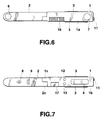
- An electrocardiographic-wave measuring apparatus 1 according to the embodiment has a folding structure. With this structure, the user carries the apparatus with him or her in a folded state as shown in FIGS. 1 and 2. When using it, he or she expands it as shown in FIGS. 6 and 7.
- a body case section 1A and an arm section 2 make up an outward form.
- the body case section 1A is shaped into a thin, flat rectangular parallelepiped.
- the arm section 2 is folded onto the top surface 1a of the body case section 1A with its one end (its left end) connected to the body case section 1A.
- the body case section 1A has first measuring electrodes 3 provided on both sides of its longitudinal case. It also has a display member 4 on the bottom surface 1b opposite to the top surface 1a onto which the arm section 2 is folded.
- the display member 4 displays the stored data items including the electrocardiographic measurements, the time, and the telephone number.
- the arm section 2 is installed on the body case section 1A as follows: one end of the body case section 1A is cut away into half to form an ark-like hinge portion 1c, and similarly one end of the corresponding arm section 2 is cut away into half to form a hinge portion 2c; thereafter, these hinge portions 1c and 2c are placed side by side and pierced with a spring pin 5 for unity. This allows the arm section 2 to rotate around the spring pin 5, thereby changing the apparatus from the folded state to the expanded state. In the expanded state, electrocardiographic waves are measured.
- a second measuring electrode 6 is provided on the arm section 2.
- the second measuring electrode 6 is placed at the tip portion of the arm section 2 as shown in FIG. 6. Measurement is made by pressing the electrode 6 against the chest.
- the second measuring electrode 6 is protruded to a specific height so as to enable contact with the chest, and is made of elastic conductive rubber, such as karaya gum, to ease a sense of contact with the skin.
- a recessed portion 7 is formed in the top surface 1a of the body case section 1A facing the second measuring electrode 6.
- the second measuring electrode 6 is housed in the recessed portion 7. This prevents the second measuring electrode 6 from being exposed to the outside and consequently dust from adhering to the electrode, thereby allowing accurate measurement. Furthermore, because there is no possibility that the electrode will interfere with another member, it will not be damaged.
- the first measuring electrode 3 may be made of the same material as that of the second measuring electrode 6 or another material such as metal.
- the tip portion of the arm section 2 at which the second measuring electrode 6 is provided is shaped into an arc. This enables smooth insertion without getting caught in the clothes when the arm section 2 is inserted into the clothes for measurement.
- the display member 4 is located on the bottom surface 1b of the body case section 1A so as to be on the side opposite to the surface on which the second measuring electrode 6 is provided. This arrangement allows the user to look at the display member 4 during measurement, facilitating the visual checking of electrocardiographic data.
- numeral 8 indicates speaker perforations made in the opposite side of the arm section 2 to the second measuring electrode 6, and 9 indicates a communication member.
- a speaker is placed inside the arm section 2 so as to correspond to the speaker perforations 8, which permits sound from the speaker to pass through during measurement or at the end of measurement.
- the communication member 9 is composed of, for example, a photocoupler provided with a phototransistor and a light-emitting diode.
- numeral 11 indicates a first switch provided on the other end of the body case section 1A.
- the switch turns on and off the electrocardiographic measurement and also the communication by the communication member 9.
- Numerals 12 and 13 indicate second and third switches provided on the bottom surface of the body case section 1A, respectively. These switches 12 and 13 are used to correct the time, display the telephone numbers stored, or change to the communication mode.
- a light-emitting diode 14 for emitting light to indicate that measurement is now being made is placed adjacent to the first switch 11 (see FIG. 4).
- An electrode jack 15 to be connected to a commercial power supply for charging is provided on one longitudinal side of the body section 1 (see FIG. 2).
- a battery cover 16 for replacing batteries (not shown) is provided (see FIG. 6). Furthermore, on the bottom surface of the body case section 1A, a switch cover 17 for protecting the internal switches (not shown) installed inside the body case section 1A is provided.
- FIG. 8 illustrate an internal configuration of the present embodiment.
- a circuit board 19 on which an LSI 18 for controlling the entire electrocardiograph is provided.
- the electrocardiographic measurements are supplied to the LSI 18 and the circuit board 19, which constitute an electric circuit member that outputs the electrocardiographic data to the display member 4 as a display signal.
- the circuit board 19 is connected to the second measuring electrode 6 via a flexible connecting board 20 extended from the body case section 1A to the inside of the arm section 2.
- the speaker 10 and the communication member 9 are mounted on the connecting board 20.
- the display member 4 is attached to the circuit board 19 and provides various indications as mentioned earlier.
- a film liquid-crystal member is used for the display member 4, which is therefore thin.
- Numeral 21 indicates a transparent plate made of glass or transparent plastic, provided on the body section 1 facing the display member 4.
- a fixed contact 22 is provided on one end of the circuit board 19. The fixed contact 22 is provided at a portion facing the first switch 11. When a movable contact 23 formed at the first switch 11 comes into contact with the fixed contact, this effects the aforementioned switching.
- FIG. 9 is a block diagram of the internal electronic circuitry of the electrocardiograph according to the embodiment.
- the electronic circuitry comprises: a electrocardiographic-wave sensing section 30 to which the electrocardiographic waves measured by the first measuring electrode 3 and the second measuring electrode 6 are supplied; a control section 31 for controlling the operation of the electrocardiograph including each circuit; a ROM 32 in which microprograms are stored; a RAM 33 for storing a plurality of data; a driver 34 for controlling the indication on the display member 4; a sound control section 35 for driving the speaker 10, a light-emitting and -receiving control section 36 for controlling the communication member 39 including a photocoupler; and a switch section 37 for outputting the signals from the first to third switches 11, 12 and 13 to the control section 31.
- the electrocardiographic-wave sensing section 30 senses and amplifies the electrocardiographic waves from the first and second measuring electrodes 3 and 6, filters the amplified electrocardiographic waves, analog-to-digital converts the filtered signals, and supplies the converted signals to the control section 31. Receiving the signals, the control section 31 controls the driver 34, which causes the display member 4 to provide an indication of plural electrocardiographic data. The control section 31 also stores the plural inputted electrocardiographic data in the RAM 33.
- FIG. 10 illustrates the internal structure of the RAM 33.
- the RAM 33 contains a display register 33a, a telephone number storage section 33b in which the telephone number of the owner of the electrocardiograph is stored, electrocardiographic complex data storage sections 33c, 33d, 33e and 33f in which the obtained electrocardiographic complex data is stored, and a work area 33g.
- four areas are given to the electrocardiographic complex data storage sections 33c to 33f, which allow four measurements to be stored.
- the stored electrocardiographic data are read from the RAM 33 when necessary, and are displayed on the display member 4. They may be outputted from the communication member 9 to the outside.
- electrocardiographic waves are measured as follows: the user rotates the folded arm section 2 to expand it; he or she then, with the first measuring electrode 3 of the body case section 1 gripped by his or her right hand, slides the arm section 2 into the opening between buttons on the front of his or her clothes or the opening in the shirt at the armpit, or slides it inside from under the clothes; and thereafter, he or she contacts the second measuring electrode 6 with the chest for measurement. Therefore, it is not necessary to apply the apparatus perpendicularly to the chest. The user has only to place the apparatus almost in parallel to the chest and press the second measuring electrode 6 against the left side of the heart in the chest. As a result, the user need not take off his or her clothes and can measure electrocardiographic waves easily and make quick measurement in case of heart attack.
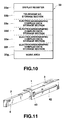
- FIGS. 11 to 13 show a second embodiment of the present invention.
- the arm section 2 can be pulled out of or withdrawn into the body section 1 on which the first measuring electrode 3 is provided.
- an opening 41 through which the arm section 2 slides is made in one end of the body section 1.
- An oblong slit 42 is made in one longitudinal side of the body section 1.
- a slide switch 43 is provided in the slit 42. The slide switch 43 passes through the slit 42 and is connected to the arm section 2. Moving the slide switch 43 along the slit 42 withdraws the entire arm section 2 into the case body 1 for storage or pulls the arm section out of the case body 42 for expansion. With the arm section expanded, electrocardiographic waves can be measured as in the previous embodiment.
- the second embodiment enables easy and quick measurement. Since the second measuring electrode 6 is housed in the case body 1, this prevents dust from adhering to the electrode.
- FIGS. 14 to 19 illustrate a third embodiment of the present invention.
- An electrocardiographic-wave measuring apparatus 50 according to the third embodiment has the same configuration as the electrocardiographic-wave measuring apparatus 1 shown in FIGS. 1 to 8, except that a connector terminal section 47 is provided on a side of the body case section 1A.
- the electrocardiographic-wave measuring apparatus 50 can measure electrocardiographic waves not only without connecting to any external circuit, but also in connection with the external connecting member 48.
- the electronic circuit 57 measures electrocardiographic waves on the basis of the signal transmitted from the external connecting section 48. In this case, the electronic circuit 57 measures electrocardiographic waves continuously as explained later.
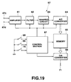
- FIG. 19 is a block diagram of the electronic circuit 57 that measures such electrocardiographic waves.
- an amplifier circuit 61 amplifies electrocardiographic waves supplied from the terminal strips 47c and 47d.
- the amplifier circuit 61 receives electrocardiographic waves from the first and second external electrodes 51 and 52.
- the amplifier circuit 61 receives electrocardiographic waves from the measuring electrodes 3 and 6.
- a filter circuit 62 removes noise components from the amplified electrocardiographic waves at the amplifier circuit 61.
- a waveform-shaping circuit 63 shapes waveforms. After the shaped signal has been analog-to-digital converted at an A/D (analog/digital) converter circuit 64, the converted signal is stored in a memory 65.
Landscapes
- Health & Medical Sciences (AREA)
- Life Sciences & Earth Sciences (AREA)
- Heart & Thoracic Surgery (AREA)
- Medical Informatics (AREA)
- Biophysics (AREA)
- Pathology (AREA)
- Engineering & Computer Science (AREA)
- Biomedical Technology (AREA)
- Cardiology (AREA)
- Physics & Mathematics (AREA)
- Molecular Biology (AREA)
- Surgery (AREA)
- Animal Behavior & Ethology (AREA)
- General Health & Medical Sciences (AREA)
- Public Health (AREA)
- Veterinary Medicine (AREA)
- Measurement And Recording Of Electrical Phenomena And Electrical Characteristics Of The Living Body (AREA)
Applications Claiming Priority (3)
| Application Number | Priority Date | Filing Date | Title |
|---|---|---|---|
| JP34061193 | 1993-12-08 | ||
| JP340611/93 | 1993-12-08 | ||
| JP34061193A JP3396937B2 (ja) | 1993-12-08 | 1993-12-08 | 心電計 |
Publications (2)
| Publication Number | Publication Date |
|---|---|
| EP0657136A1 true EP0657136A1 (fr) | 1995-06-14 |
| EP0657136B1 EP0657136B1 (fr) | 2000-05-31 |
Family
ID=18338640
Family Applications (1)
| Application Number | Title | Priority Date | Filing Date |
|---|---|---|---|
| EP94119352A Expired - Lifetime EP0657136B1 (fr) | 1993-12-08 | 1994-12-07 | Electrocardiographe |
Country Status (4)
| Country | Link |
|---|---|
| EP (1) | EP0657136B1 (fr) |
| JP (1) | JP3396937B2 (fr) |
| DE (1) | DE69424753T2 (fr) |
| SG (1) | SG46396A1 (fr) |
Cited By (6)
| Publication number | Priority date | Publication date | Assignee | Title |
|---|---|---|---|---|
| WO2001070101A3 (fr) * | 2000-03-23 | 2002-03-28 | Shl Telemedicine Internat Ltd | Dispositif de signalisation d'ecg portatif |
| US8467859B2 (en) | 2006-09-07 | 2013-06-18 | Telozo Gmbh | Method and device for deriving and evaluating cardiovascular information from curves of the cardiac current, in particular for applications in telemedicine |
| CN103519805A (zh) * | 2012-07-06 | 2014-01-22 | 周常安 | 手持式心电检测装置 |
| WO2014138532A1 (fr) * | 2013-03-07 | 2014-09-12 | Medtronic, Inc. | Dispositifs sous-cutanés de surveillance cardiaque, systèmes et procédés |
| WO2020167154A1 (fr) * | 2019-02-13 | 2020-08-20 | Vlaskalic Srdjan | Dispositif de pliage en taille de poche avec électrodes intégrées pour l'enregistrement, le traitement et la transmission avec trois dérivations d'électrocardiographie |
| CN116807489A (zh) * | 2023-08-30 | 2023-09-29 | 北京五维康科技有限公司 | 手持便携式心电仪 |
Families Citing this family (3)
| Publication number | Priority date | Publication date | Assignee | Title |
|---|---|---|---|---|
| JPH0956686A (ja) * | 1995-08-28 | 1997-03-04 | Casio Comput Co Ltd | 心電計 |
| JP2009082364A (ja) * | 2007-09-28 | 2009-04-23 | Omron Healthcare Co Ltd | 携帯型心電計 |
| CN105380641B (zh) * | 2015-12-11 | 2018-12-07 | 北京五维康科技有限公司 | 一种手持式心血管健康监测装置 |
Citations (3)
| Publication number | Priority date | Publication date | Assignee | Title |
|---|---|---|---|---|
| EP0265694A1 (fr) * | 1986-10-17 | 1988-05-04 | Hans-Joachim Uhlemann | Dispositif de diagnostic cardiaque |
| US4844090A (en) * | 1986-07-28 | 1989-07-04 | Yukio Sekine | Pencil type heart potential waveform measuring device |
| FR2666977A1 (fr) * | 1990-09-20 | 1992-03-27 | Lefebvre Jean Marie | Electrocardiographe portable. |
-
1993
- 1993-12-08 JP JP34061193A patent/JP3396937B2/ja not_active Expired - Fee Related
-
1994
- 1994-12-07 EP EP94119352A patent/EP0657136B1/fr not_active Expired - Lifetime
- 1994-12-07 DE DE69424753T patent/DE69424753T2/de not_active Expired - Fee Related
- 1994-12-07 SG SG1996004240A patent/SG46396A1/en unknown
Patent Citations (3)
| Publication number | Priority date | Publication date | Assignee | Title |
|---|---|---|---|---|
| US4844090A (en) * | 1986-07-28 | 1989-07-04 | Yukio Sekine | Pencil type heart potential waveform measuring device |
| EP0265694A1 (fr) * | 1986-10-17 | 1988-05-04 | Hans-Joachim Uhlemann | Dispositif de diagnostic cardiaque |
| FR2666977A1 (fr) * | 1990-09-20 | 1992-03-27 | Lefebvre Jean Marie | Electrocardiographe portable. |
Cited By (11)
| Publication number | Priority date | Publication date | Assignee | Title |
|---|---|---|---|---|
| WO2001070101A3 (fr) * | 2000-03-23 | 2002-03-28 | Shl Telemedicine Internat Ltd | Dispositif de signalisation d'ecg portatif |
| US8467859B2 (en) | 2006-09-07 | 2013-06-18 | Telozo Gmbh | Method and device for deriving and evaluating cardiovascular information from curves of the cardiac current, in particular for applications in telemedicine |
| CN103519805A (zh) * | 2012-07-06 | 2014-01-22 | 周常安 | 手持式心电检测装置 |
| WO2014138532A1 (fr) * | 2013-03-07 | 2014-09-12 | Medtronic, Inc. | Dispositifs sous-cutanés de surveillance cardiaque, systèmes et procédés |
| CN105025784A (zh) * | 2013-03-07 | 2015-11-04 | 美敦力公司 | 皮下心脏监测装置、系统和方法 |
| US9186513B2 (en) | 2013-03-07 | 2015-11-17 | Medtronic, Inc. | Subcutaneous cardiac monitoring devices, systems and methods |
| CN105025784B (zh) * | 2013-03-07 | 2018-02-27 | 美敦力公司 | 皮下心脏监测装置、系统和方法 |
| WO2020167154A1 (fr) * | 2019-02-13 | 2020-08-20 | Vlaskalic Srdjan | Dispositif de pliage en taille de poche avec électrodes intégrées pour l'enregistrement, le traitement et la transmission avec trois dérivations d'électrocardiographie |
| US11406311B2 (en) | 2019-02-13 | 2022-08-09 | Heartpal Tech Doo | Pocket-size folding device with integrated electrodes for recording, processing and transmission with three ECG leads |
| CN116807489A (zh) * | 2023-08-30 | 2023-09-29 | 北京五维康科技有限公司 | 手持便携式心电仪 |
| CN116807489B (zh) * | 2023-08-30 | 2023-12-01 | 北京五维康科技有限公司 | 手持便携式心电仪 |
Also Published As
| Publication number | Publication date |
|---|---|
| HK1013400A1 (en) | 1999-08-27 |
| JP3396937B2 (ja) | 2003-04-14 |
| DE69424753T2 (de) | 2000-09-21 |
| JPH07155301A (ja) | 1995-06-20 |
| SG46396A1 (en) | 1998-02-20 |
| EP0657136B1 (fr) | 2000-05-31 |
| DE69424753D1 (de) | 2000-07-06 |
Similar Documents
| Publication | Publication Date | Title |
|---|---|---|
| US5505202A (en) | Portable and collapsable electrocardiograph | |
| CN111417341B (zh) | 心电图测量设备 | |
| US20050143670A1 (en) | Portable electrocardiograph | |
| US8315687B2 (en) | Handheld, repositionable ECG detector | |
| JP2007209609A (ja) | 携帯型心電計 | |
| EP0657136B1 (fr) | Electrocardiographe | |
| KR20200075780A (ko) | 무선 심전도 측정장치 | |
| KR101432813B1 (ko) | 폴더 방식의 휴대용 심전도 측정 장치 | |
| EP1985231A1 (fr) | Electrocardiographe portable | |
| EP2000085A2 (fr) | Appareil ECG portable | |
| JP4239836B2 (ja) | 生体情報測定装置 | |
| KR102213513B1 (ko) | 심전도 측정 장치 | |
| JPH0956686A (ja) | 心電計 | |
| JP2023061111A (ja) | ウェアラブル型心電計測装置 | |
| HK1013400B (en) | Electrocardiograph | |
| KR102269411B1 (ko) | 심전도 측정 장치 | |
| CN213075626U (zh) | 一种心电血氧监测仪及体检监测系统 | |
| JP2000135201A (ja) | 無線接続を有する診断装置 | |
| CN219422827U (zh) | 一种心电记录仪结构 | |
| JP2009131461A (ja) | 携帯型心電計用外部電極ユニットおよびこれを備えた携帯型心電計セット | |
| JPH0228888Y2 (fr) | ||
| WO2007091380A1 (fr) | Électrocardiographe portable | |
| EP4176803A1 (fr) | Dispositif portable d'ecg | |
| CZ2017592A3 (cs) | Univerzální monitor příložný s rozšířenými funkcemi |
Legal Events
| Date | Code | Title | Description |
|---|---|---|---|
| PUAI | Public reference made under article 153(3) epc to a published international application that has entered the european phase |
Free format text: ORIGINAL CODE: 0009012 |
|
| 17P | Request for examination filed |
Effective date: 19941207 |
|
| AK | Designated contracting states |
Kind code of ref document: A1 Designated state(s): DE FR GB NL SE |
|
| RAP1 | Party data changed (applicant data changed or rights of an application transferred) |
Owner name: CASIO COMPUTER CO., LTD. |
|
| 17Q | First examination report despatched |
Effective date: 19980626 |
|
| GRAG | Despatch of communication of intention to grant |
Free format text: ORIGINAL CODE: EPIDOS AGRA |
|
| GRAG | Despatch of communication of intention to grant |
Free format text: ORIGINAL CODE: EPIDOS AGRA |
|
| GRAH | Despatch of communication of intention to grant a patent |
Free format text: ORIGINAL CODE: EPIDOS IGRA |
|
| GRAH | Despatch of communication of intention to grant a patent |
Free format text: ORIGINAL CODE: EPIDOS IGRA |
|
| GRAA | (expected) grant |
Free format text: ORIGINAL CODE: 0009210 |
|
| AK | Designated contracting states |
Kind code of ref document: B1 Designated state(s): DE FR GB NL SE |
|
| REF | Corresponds to: |
Ref document number: 69424753 Country of ref document: DE Date of ref document: 20000706 |
|
| ET | Fr: translation filed | ||
| PLBE | No opposition filed within time limit |
Free format text: ORIGINAL CODE: 0009261 |
|
| STAA | Information on the status of an ep patent application or granted ep patent |
Free format text: STATUS: NO OPPOSITION FILED WITHIN TIME LIMIT |
|
| 26N | No opposition filed | ||
| REG | Reference to a national code |
Ref country code: GB Ref legal event code: IF02 |
|
| PGFP | Annual fee paid to national office [announced via postgrant information from national office to epo] |
Ref country code: NL Payment date: 20071203 Year of fee payment: 14 |
|
| PGFP | Annual fee paid to national office [announced via postgrant information from national office to epo] |
Ref country code: SE Payment date: 20071205 Year of fee payment: 14 |
|
| PGFP | Annual fee paid to national office [announced via postgrant information from national office to epo] |
Ref country code: GB Payment date: 20071205 Year of fee payment: 14 Ref country code: FR Payment date: 20071210 Year of fee payment: 14 |
|
| PGFP | Annual fee paid to national office [announced via postgrant information from national office to epo] |
Ref country code: DE Payment date: 20071129 Year of fee payment: 14 |
|
| EUG | Se: european patent has lapsed | ||
| GBPC | Gb: european patent ceased through non-payment of renewal fee |
Effective date: 20081207 |
|
| NLV4 | Nl: lapsed or anulled due to non-payment of the annual fee |
Effective date: 20090701 |
|
| REG | Reference to a national code |
Ref country code: FR Ref legal event code: ST Effective date: 20090831 |
|
| PG25 | Lapsed in a contracting state [announced via postgrant information from national office to epo] |
Ref country code: DE Free format text: LAPSE BECAUSE OF NON-PAYMENT OF DUE FEES Effective date: 20090701 |
|
| PG25 | Lapsed in a contracting state [announced via postgrant information from national office to epo] |
Ref country code: NL Free format text: LAPSE BECAUSE OF NON-PAYMENT OF DUE FEES Effective date: 20090701 Ref country code: GB Free format text: LAPSE BECAUSE OF NON-PAYMENT OF DUE FEES Effective date: 20081207 |
|
| PG25 | Lapsed in a contracting state [announced via postgrant information from national office to epo] |
Ref country code: FR Free format text: LAPSE BECAUSE OF NON-PAYMENT OF DUE FEES Effective date: 20081231 |
|
| PG25 | Lapsed in a contracting state [announced via postgrant information from national office to epo] |
Ref country code: SE Free format text: LAPSE BECAUSE OF NON-PAYMENT OF DUE FEES Effective date: 20081208 |