EP0657220A2 - Centrifugeuse filtrante - Google Patents
Centrifugeuse filtrante Download PDFInfo
- Publication number
- EP0657220A2 EP0657220A2 EP94118804A EP94118804A EP0657220A2 EP 0657220 A2 EP0657220 A2 EP 0657220A2 EP 94118804 A EP94118804 A EP 94118804A EP 94118804 A EP94118804 A EP 94118804A EP 0657220 A2 EP0657220 A2 EP 0657220A2
- Authority
- EP
- European Patent Office
- Prior art keywords
- rear wall
- filter
- centrifuge according
- filter centrifuge
- filter drum
- Prior art date
- Legal status (The legal status is an assumption and is not a legal conclusion. Google has not performed a legal analysis and makes no representation as to the accuracy of the status listed.)
- Granted
Links
Images


Classifications
-
- B—PERFORMING OPERATIONS; TRANSPORTING
- B04—CENTRIFUGAL APPARATUS OR MACHINES FOR CARRYING-OUT PHYSICAL OR CHEMICAL PROCESSES
- B04B—CENTRIFUGES
- B04B9/00—Drives specially designed for centrifuges; Arrangement or disposition of transmission gearing; Suspending or balancing rotary bowls
- B04B9/12—Suspending rotary bowls ; Bearings; Packings for bearings
-
- B—PERFORMING OPERATIONS; TRANSPORTING
- B04—CENTRIFUGAL APPARATUS OR MACHINES FOR CARRYING-OUT PHYSICAL OR CHEMICAL PROCESSES
- B04B—CENTRIFUGES
- B04B3/00—Centrifuges with rotary bowls in which solid particles or bodies become separated by centrifugal force and simultaneous sifting or filtering
-
- B—PERFORMING OPERATIONS; TRANSPORTING
- B04—CENTRIFUGAL APPARATUS OR MACHINES FOR CARRYING-OUT PHYSICAL OR CHEMICAL PROCESSES
- B04B—CENTRIFUGES
- B04B7/00—Elements of centrifuges
- B04B7/02—Casings; Lids
Definitions
- the invention relates to a filter centrifuge with a filter drum rotatably mounted in a process housing about a horizontal axis, which is supported in a self-supporting manner in a bearing, with a drive for the filter drum and with a machine frame supporting the process housing, the bearing of the filter drum and the drive.
- Such a filter centrifuge is known for example from the publication "Knott, systematics in the construction of machines and apparatus for the chemical industry, design 1967, number 6, pages 217 to 222, figure 5".
- the process space is provided with an end cover. Access to the process room and thus to the centrifuge drum is made possible by the opening of the process room closed by the lid. Maintenance work on the centrifuge drum is carried out within the process room. For larger work on the centrifuge drum, which must be carried out in a workshop, the centrifuge drum must be removed, which also involves work in the process room of the centrifuge. A special tool required for removing the centrifuge drum, such as a lifting bracket, must be available on the side of the opening of the process space. If work on the storage or the seal of the centrifuge drum is necessary, both the centrifuge drum must be be expanded, as well as the expansion of the warehouse through the processing room.
- the filter centrifuge is a filter centrifuge with clean room separation, as is known, for example, from EP 0 379 452, all of the above-mentioned work is to be carried out in the clean room of the system which has the process housing, which likewise entails the risk of contamination of the clean room .
- a known filter centrifuge cannot be integrated into production during the maintenance work described.
- Filter centrifuges are also known in which the main shaft forms a unit with the bearings and the seals, a so-called cartridge, together with a self-supporting bearing housing.
- These storage units can be installed fully functional independently of the rest of the filter centrifuge, so that the cartridge can be completely removed from the filter centrifuge when work is being carried out on seals or on storage and the necessary work can be carried out, for example in a workshop.
- This storage unit depends on The centrifuge can be set up either through the process room or removed from the rear of the process room. But even if such a storage unit is provided, work in the process space of the centrifuge is required to remove the storage unit. Even if work has to be carried out on the centrifuge drum, this must take place within the process room. This work in the process room entails the disadvantages already described at the beginning.
- Filter centrifuges are also known in which the storage unit described above forms an overall unit together with the drum.
- the removal of this entire unit from a filter centrifuge also requires work in the process space, since the entire unit must either be removed through the process space or the entire process housing must be removed from the machine frame.
- the disadvantages of cross-contamination described above also occur here.
- the object of the invention is to provide a generic filter centrifuge in which the risk of cross-contamination is reduced to a minimum during maintenance work on the filter centrifuge which relate to the filter drum or the storage of the filter drum.
- the machine frame has a base frame and a substantially horizontally movable bearing frame relative thereto, that the process housing is attached to the base frame and that the storage of the filter drum is provided on the bearing frame.
- This configuration can be provided both in the case of filter centrifuges which operate continuously and in the case of discontinuously operating filters. Due to the solution of the task specified in claim 1, the process space separation of the filter centrifuge is maintained even during the maintenance work. All work on the filter drum, on internals in the drum and on the storage can be carried out outside the process room of the centrifuge, since the filter drum, which is supported together with its storage on the horizontally movable bearing frame, can be removed from the process housing by a horizontal movement of the bearing frame. It is advantageous if the bearing frame can be moved translationally in the axial direction of the filter drum, wherein in particular the base frame can be provided with a sliding track and the bearing frame can be slidably mounted on the sliding track of the base frame.
- the sliding track is formed by rails on which support rollers provided on the bearing frame roll.
- a particularly advantageous self-centering results if the inner circumference of the opening widens conically towards the bearing frame and if the outer circumference of the rear wall cover tapers conically towards the process housing.
- a mechanical lock can be provided between the rear wall and the rear wall cover.
- the mechanical locking has at least one locking element that can be moved in the radial direction, is mounted on one of the two parts to be locked, rear wall or rear wall cover, and interacts with a locking counter-element on the other of the two parts to be locked.
- the rear wall cover has a further circumferential groove in which a circumferential clamping ring provided with at least one radial slot is used as a locking element, the clamping ring being adjustable in the circumferential direction in the region of its radial slot by changing the width of the radial slot, as a result of which the diameter changes of the clamping ring changes, and wherein an inner circumferential groove is provided as a locking counter-element on the inner circumference of the rear wall opening, which is designed for engagement with the clamping ring.
- This configuration has the advantage that the locking between the rear wall cover and the rear wall takes place evenly over the circumference and can be carried out by a single actuation, namely the spreading of the clamping ring.
- the rear wall cover is provided with a flange which overlaps the rear wall opening, which can be fastened to the rear wall, screw bolts are preferably provided for fastening the flange to the rear wall.
- a special embodiment of the filter centrifuge is characterized in that the rear wall is firmly connected to the base frame and that the process housing is removably attached to the rear wall. In this way, both the bearing frame provided with the filter drum and its storage and the process housing can be removed and replaced, so that a production-related conversion of a centrifuge, for example from a peeling centrifuge to a push centrifuge, is possible with little effort.
- the rear wall can be part of a partition between a clean room accommodating the process housing and a machine room accommodating the base frame and the bearing frame of a building surrounding the filter centrifuge.
- the filter centrifuge can be used precisely at the point of separation between a clean room and a machine room of a building, and all maintenance work on the machine can be carried out in the machine room without the clean room having to be walked on.
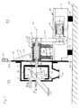
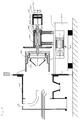
- Fig. 1 shows a first embodiment of the invention using the example of a peeler centrifuge.
- a base frame 1 is supported and fixed on the floor 60 of a production building via vibration bearings 12, 12 '.
- the base frame 1 On its upper side, the base frame 1 is provided with a sliding track 10, which consists of at least one horizontally running rail 11.
- a bearing frame 2 comprises a horizontally arranged support tube 20 which is supported on support rollers 22, 22 'via support feet 21, 21'.
- the support rollers 22, 22 ' are mounted on the rail 11 so that the bearing frame 2 can be moved horizontally in translation with respect to the base frame 1.
- a filter drum shaft 40 is mounted in bearings 28, 28 'in the support tube 20 so as to be rotatable about a horizontal axis 40'.
- the filter drum shaft 40 protrudes from the support tube 20 on both sides, a shaft seal 29, 29 'protecting the respective bearings 28, 28' being provided in the region of the respective opening of the support tube 20.
- the base frame 1 has on its first (left in FIG. 1) end face a vertically extending wall which forms the rear wall 13 of a process housing 3.
- the process housing 3 is fastened to the rear wall 13 on the side facing away from the base frame 1 in a known manner, for example by means of screws.
- the process housing 3, together with the rear wall 13, encloses a process chamber 30 which is provided in its lower region with an outlet opening 31 for filtrate.
- a filter drum 4 is provided within the process housing 3, which is fastened on the first free end of the filter drum shaft 40 and can rotate with it about the axis 40 ′ within the process space.
- the filter drum 4 has a peripheral jacket 41, in which a plurality of radially extending filter openings 42 is provided.
- the end face 43 of the filter drum 4 facing away from the filter drum shaft 40 has a large central opening 43 '. Through this central opening 43 ', a peeling knife 32 reaches into the inside of the drum and can rest with a peeling knife edge 32' in the upper region of the filter drum 4 on the inside of the peripheral jacket 41.
- the peeling knife 32 which is pivotably mounted on a horizontal swivel shaft 32 ′′ penetrating the process housing 3, is swiveled against the inside of the circumferential casing 41 of the filter drum 4 in order to be able to Peel knife edge 32 'to peel off the filter cake adhering to the inside of the circumferential casing 41 during the rotation of the filter drum 4.
- the removed filter cake falls into an inclined chute 33 which penetrates the opening 43 'of the filter drum 4 and the process housing 3 and opens into an outlet opening 33' for the solid.
- a filling tube 34 is provided within the filter drum 4 for the suspension to be filtered, which is fed in the direction of the arrow 34 '.
- a drive 5 which has a drive machine 50, for example an electric motor, which transmits the torque to a second V-belt wheel 44 attached to the second free end of the filter drum shaft via a first V-belt wheel 52 and a V-belt acting as a force transmission member 51 in this way, the filter drum 4 is rotated.
- a drive machine 50 for example an electric motor, which transmits the torque to a second V-belt wheel 44 attached to the second free end of the filter drum shaft via a first V-belt wheel 52 and a V-belt acting as a force transmission member 51 in this way, the filter drum 4 is rotated.
- the rear wall 13 is provided with a rear wall opening 14, the clear width of which is greater than the diameter of the filter drum 4.
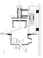
- the filter drum 4 can penetrate the opening 14, so that the bearing frame 2 shown in FIG. 1 together with the filter drum 4 and the filter drum shaft 40 can be moved to the right after loosening the transmission member 51, the filter drum 4 being pulled out of the process housing 3.
- This position is shown in Fig. 2.
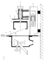
- a rear wall cover 23 is provided which corresponds in its dimensions and in its contour to the rear wall opening 14. After the filter drum 4 has been pulled out of the process housing 3 while horizontally displacing the bearing frame 2, the rear wall opening 14 can be closed with a sealing cover 14 'in order to close off the process chamber again, as can be seen in FIG. 3.
- the rear wall 13 is part of a building partition 61, with which the building is divided into a clean room 62, in which the process housing 3 is located, and into a machine room 63, in which the base frame 1, the bearing frame 2 and the drive 5 are located .
- the sealing connection between the rear wall 13 and the building partition 61 and the floor 60 represent elastic components 64, 65.
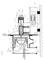
- FIGS. 4 and 5 Another embodiment of the invention is shown in FIGS. 4 and 5, the filter centrifuge shown there being a push-type filter centrifuge.
- the reference numerals in the illustration of FIGS. 4 and 5 are increased by 100 in each case compared to FIGS. 1 to 3.
- the filter drum shaft 140 which is mounted within the support tube 120 of the bearing frame 102, is designed as a hollow shaft, and an inner filter drum shaft 145 is axially displaceable in it, but is connected to the filter drum shaft 140 in a rotationally fixed manner.
- the filter drum shaft 140 is connected to the filter drum 104, which is U-shaped in cross section. Inside the filter drum 104 is a filter drum insert, which is likewise U-shaped in cross section 104 'is provided, which is connected to the inner filter drum shaft 145 and is axially displaceable with the latter.
- the inner filter drum shaft 145 is provided at its end facing away from the filter drum insert 104 'with a piston 146' which is received in an axially displaceable manner in a cylinder 146.
- Axial actuation of the piston 146 'and with it the filter drum insert 104' takes place by pressurizing the piston-cylinder unit 146, 146 'in a manner known per se.
- the pressure fluid is supplied to the piston-cylinder unit 146, 146 'rotating with the inner filter drum shaft 145 via a rotary coupling connection 146''and a forward stroke bore 147 or a return stroke bore 147' in the cylinder 146.
- Axial displacement of the inner filter drum shaft 145 in the direction of the process housing 103 causes the filter drum insert 104 'to be shifted to the left in FIG the outlet opening 133 'for the solid leaves the process housing.
- rinsing or washing pipes 135 are also provided, with which rinsing or washing liquid can be brought to the inside of the filter drum 104 and the filter drum insert 104 '.
- the structure and mode of operation of the filter drum arrangement of this shear filter centrifuge are known in principle, but the mounting of such a shear filter centrifuge on the horizontally movable bearing frame 102 is new.
- the filter drum arrangement of the thrust filter centrifuge is moved out in the same manner as has been described with reference to FIGS. 1 and 2.
- the arrangement of the filter drum 104 and the filter drum insert 104 'moved out of the process housing 103 together with the bearing frame 102, the filter drum shaft 140, the inner filter drum shaft 145 acting as a push rod, the second V-belt pulley 144 and the piston-cylinder unit 146, 146' as well as the Rotary transmission connections 146 ′′ for the pressure fluid is shown in FIG. 5.
- the drive unit 105 remains stationary on the base frame; it is only necessary to release the transmission link 151.
- the length of the rail 111 is dimensioned such that the filter drum 104 can be completely moved out of the process housing 103.
- the filter centrifuge according to the invention can be assembled in a modular manner, with a conversion, for example, of a peeling centrifuge into a push centrifuge, e.g. for a production changeover, can be done quickly and easily.
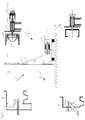
- a modification is shown schematically in FIG. 6.
- the base frame 1 with the drive 5 and the rear wall 13 is shown.
- the rear wall 13 is closed by means of the closure cover 14 ', so that a hermetic seal between the clean room 62 and the machine room 63 is ensured.
- the process housing 3 of the peeling centrifuge must be removed in the clean room and the housing 103 of the push centrifuge must be attached to the rear wall 13, which is symbolized by the two arrows A and A '.
- the extended storage frame 2 is included the filter drum 4 of the peeling centrifuge is lifted off the sliding track 10 by means of a hoist, and the bearing frame 102 with the filter drum arrangement 104, 104 'and the piston-cylinder unit 146, 146' of the push centrifuge is placed on the sliding track 10 (arrows B and B ').
- the bearing frame 102 can be moved and locked in the direction of the process housing 103, as a result of which the conversion is completed. If necessary, the rear wall cover 123 can also be mechanically locked in the rear wall 13.
- FIG. 7 shows different sealing variants between the rear wall cover 23 and the rear wall 13.
- 7a shows a simple contact seal, in which the inner circumference of the opening 14, which widens conically towards the bearing frame, and the outer circumference of the rear wall cover 23, which tapers conically towards the process housing, touch.
- FIG. 7b shows a sealing variant in which the rear wall cover 23 is provided with a circumferential groove 25, in which a sealing element 24 designed as an O-ring is inserted.
- the embodiment according to FIG. 7b already provides good sealing results.
- the configuration according to FIG. 7c is suitable for even higher demands on the seal between the process room and the environment or between the process room and the machine room.
- FIGS. 8a, 8b and 8c Such a mechanical lock is shown in FIGS. 8a, 8b and 8c, with FIG. 8c showing a view in the direction of the arrow X in FIG. 8b.
- a first circumferential groove 25, into which a sealing element 24 is inserted, is provided on the outer circumference of the rear wall cover 23.
- the sealing element 24 acts, as in FIG. 7b, in a sealing manner with the inner circumference of the opening 14 of the rear wall 13.
- a further circumferential groove 27 is formed in the rear wall cover 23 at an axial distance from the circumferential groove 25 facing the machine room 63.
- a circumferential clamping ring 26 ' provided with a radial slot 26' 'is inserted in the further circumferential groove 27. The clamping ring 26 'forms a locking element 26.
- the clamping ring 26' is provided in the region of its radial slot 26 '' with a clamping screw connection 26 '' ', by means of which the clamping ring 26' can be adjusted in the circumferential direction while changing the width of the radial slot 26 '' .
- An inner circumferential groove 15 is provided on the inner circumference of the rear wall opening 14 and is designed for engagement with the clamping ring 26 '.
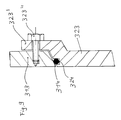
- FIG. 9 shows an alternative possibility of fastening the rear wall cover to the rear wall, the reference numerals being increased by the value 300 compared to the first embodiment of the invention shown in FIG. 1.
- the rear wall 313 and the rear wall cover 323 are sealed in the manner shown in FIG. 7b by means of a seal 324.
- the rear wall cover 323 has a flange 323 'which overlaps the rear wall opening 314 and which can be fastened to the rear wall 313 by means of screw bolts 323' '.
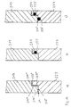
- FIG. 10a shows an alternative embodiment of the seal between the rear wall and the rear wall cover, the reference numerals being increased by the value 200 compared to the first embodiment.
- FIG. 10a shows a simple seal in which the rear wall 213 is designed in a stepped manner in the region of the opening 214, the opening having a section 214 ′ of smaller diameter on the process room side and a region 214 ′′ of larger diameter on the machine room side. A radial annular surface 214 ′′ ′′ is formed between these two diameters.
- the rear wall cover 223 is also designed in a graduated manner in the region of its outer circumference, a circumferential section 223 'of smaller diameter on the process chamber side and a circumferential section 223''of larger diameter on the machine room side being provided, which are connected to one another via a radial surface 223''''.
- FIG. 10b shows an embodiment with better sealing properties, a groove 225, in which a seal 224 is inserted, being provided in the radial annular surface 223 '' 'of the rear wall cover 223.
- the configuration according to FIG. 10c is intended for particularly high demands on the seal, wherein in addition to the seal shown in FIG. 10b, a further groove 225 'is formed in the peripheral section 223' of the rear wall cover 223 on the process chamber side and is provided with a seal 224 '.
- the subdivision of the machine frame of the filter centrifuge into the base frame 1 and the bearing frame 2 creates a simplified structure of a filter centrifuge, which makes it possible to reduce the vertical integration in the manufacture of a filter centrifuge. If the base frames of several machine types are identical, as has been described in connection with FIG. 6, not only can a simple exchange of individual parts, such as the filter drum, be carried out, but it can also be changed quickly from one centrifuge type to another what is required, for example, in the case of production changes or changes in the product properties of the product to be manufactured.
Landscapes
- Centrifugal Separators (AREA)
Applications Claiming Priority (2)
| Application Number | Priority Date | Filing Date | Title |
|---|---|---|---|
| DE4342471A DE4342471C1 (de) | 1993-12-13 | 1993-12-13 | Filterzentrifuge |
| DE4342471 | 1993-12-13 |
Publications (3)
| Publication Number | Publication Date |
|---|---|
| EP0657220A2 true EP0657220A2 (fr) | 1995-06-14 |
| EP0657220A3 EP0657220A3 (fr) | 1995-09-27 |
| EP0657220B1 EP0657220B1 (fr) | 1999-09-22 |
Family
ID=6504877
Family Applications (1)
| Application Number | Title | Priority Date | Filing Date |
|---|---|---|---|
| EP94118804A Expired - Lifetime EP0657220B1 (fr) | 1993-12-13 | 1994-11-30 | Centrifugeuse filtrante |
Country Status (3)
| Country | Link |
|---|---|
| US (1) | US5582726A (fr) |
| EP (1) | EP0657220B1 (fr) |
| DE (2) | DE4342471C1 (fr) |
Cited By (1)
| Publication number | Priority date | Publication date | Assignee | Title |
|---|---|---|---|---|
| CN104190554A (zh) * | 2014-08-05 | 2014-12-10 | 安徽奥冠环保设备制造有限公司 | 离心机机壳自锁机构 |
Families Citing this family (8)
| Publication number | Priority date | Publication date | Assignee | Title |
|---|---|---|---|---|
| US7396324B2 (en) * | 2003-10-17 | 2008-07-08 | Hitachi Koki Co., Ltd. | Centrifugal separator with first and second control panels |
| KR100795159B1 (ko) | 2004-08-09 | 2008-01-16 | 프라임 솔루션즈 인코포레이티드 | 액체추출장치, 액체추출장치를 세척하는 방법 및 그 액체 추출 시스템 |
| EP1943006A4 (fr) * | 2005-10-28 | 2009-11-11 | Prime Solution Inc | Presse a ventilateur tournant |
| DE102006011895A1 (de) * | 2006-03-15 | 2007-09-20 | Westfalia Separator Ag | Separatoranordnung in sanitärer Ausführung |
| US8662315B2 (en) * | 2008-07-14 | 2014-03-04 | Prime Solution, Inc. | Rotary fan press |
| CN102614997A (zh) * | 2012-03-15 | 2012-08-01 | 张家港市腾龙机械制造有限公司 | 卧式离心机 |
| KR20260032643A (ko) * | 2017-12-19 | 2026-03-09 | 제로스 리미티드 | 처리 장치용 필터 |
| CN112159754B (zh) * | 2020-10-12 | 2021-09-03 | 湖州市第一人民医院 | 一种外泌体肿瘤疫苗制作设备 |
Family Cites Families (6)
| Publication number | Priority date | Publication date | Assignee | Title |
|---|---|---|---|---|
| US3365066A (en) * | 1967-03-07 | 1968-01-23 | John D. Howell | Centrifuge |
| DE3617769C1 (en) * | 1986-05-27 | 1987-10-08 | Krauss Maffei Ag | Filter centrifuge |
| FR2641715B1 (fr) * | 1989-01-19 | 1991-04-12 | Robatel Slpi | Essoreuse centrifuge a cuve articulee pour filtration en atmosphere sterile |
| DE3916266C1 (fr) * | 1989-05-19 | 1990-08-30 | Heinkel Industriezentrifugen Gmbh + Co, 7120 Bietigheim-Bissingen, De | |
| DE59009219D1 (de) * | 1990-09-24 | 1995-07-13 | Heinkel Ind Zentrifugen | Stülpfilterzentrifuge. |
| US5421997A (en) * | 1991-05-04 | 1995-06-06 | Heinkel Industriezentrifugen Gmbh & Co. Kg | Sleeve filter centrifuge |
-
1993
- 1993-12-13 DE DE4342471A patent/DE4342471C1/de not_active Expired - Lifetime
-
1994
- 1994-11-30 DE DE59408765T patent/DE59408765D1/de not_active Expired - Lifetime
- 1994-11-30 EP EP94118804A patent/EP0657220B1/fr not_active Expired - Lifetime
- 1994-12-12 US US08/354,583 patent/US5582726A/en not_active Expired - Lifetime
Cited By (1)
| Publication number | Priority date | Publication date | Assignee | Title |
|---|---|---|---|---|
| CN104190554A (zh) * | 2014-08-05 | 2014-12-10 | 安徽奥冠环保设备制造有限公司 | 离心机机壳自锁机构 |
Also Published As
| Publication number | Publication date |
|---|---|
| US5582726A (en) | 1996-12-10 |
| EP0657220A3 (fr) | 1995-09-27 |
| EP0657220B1 (fr) | 1999-09-22 |
| DE4342471C1 (de) | 1995-05-04 |
| DE59408765D1 (de) | 1999-10-28 |
Similar Documents
| Publication | Publication Date | Title |
|---|---|---|
| EP1603679B1 (fr) | Centrifugeuse a filtre de recouvrement | |
| EP0936948B1 (fr) | Centrifugeuse a filtre inversable | |
| EP1064119A2 (fr) | Machine a transfert rotatif | |
| DE2709894A1 (de) | Filterzentrifuge | |
| EP0657220B1 (fr) | Centrifugeuse filtrante | |
| DE69608081T2 (de) | Vorrichtung zur Extrusion von Plastomeren, Elastomeren und ähnlichen Materialien mit konvergierenden Schnecken | |
| EP0872573A1 (fr) | Dispositif de traitement sous vide de dépÔt de couches minces | |
| EP0144904A2 (fr) | Joint d'étanchéité pour palier de centrifugeuse | |
| DE3344805A1 (de) | Hub-drehtisch-vorrichtung | |
| EP0652051A1 (fr) | Dispositif d'étanchéité pour tambour d'une centrifugeuse à filtre réversible | |
| WO2001038070A1 (fr) | Dispositif et procede permettant de realiser un mouvement lineaire en deux temps | |
| DE2327532B2 (de) | Flüssigkeitsfilter mit selbsttätiger Reinigung | |
| DE3804502A1 (de) | Vorrichtung zum bearbeiten von rotationssymmetrischen werkstueckflaechen | |
| EP1797959B1 (fr) | Dispositif de centrifugation amélioré destiné à éviter la contamination croisée | |
| DE3600492A1 (de) | Filtervorrichtung | |
| DE3876705T2 (de) | Gleitlager mit zwei konzentrischen tragflaechen. | |
| EP0448736B1 (fr) | Centrifugeuse à filtre réversible | |
| DE3430508C2 (fr) | ||
| DE2718235C2 (de) | Mehrstufige Schubzentrifuge | |
| EP0503335A1 (fr) | Presse sous vide, en particulier pour matériaux céramiques | |
| EP0511608A1 (fr) | Unité d'alimentation dans une trémie, en particulier pour une machine de fabrication de saucisses | |
| DE10156589A1 (de) | Zentrifuge | |
| DE69505056T2 (de) | Drehtisch, angetrieben von mit gesteuerten Achsen arbeitenden Werkzeugmaschinen | |
| EP0887536A1 (fr) | Procédé pour l'inspection d'un palier et procédé pour le démontage d'une tige de piston d'un grand moteur diesel et outil et moteur pour l'exécution de ces procédés | |
| DE29509271U1 (de) | Feststoffmühle |
Legal Events
| Date | Code | Title | Description |
|---|---|---|---|
| PUAI | Public reference made under article 153(3) epc to a published international application that has entered the european phase |
Free format text: ORIGINAL CODE: 0009012 |
|
| AK | Designated contracting states |
Kind code of ref document: A2 Designated state(s): CH DE FR GB IE IT LI |
|
| PUAL | Search report despatched |
Free format text: ORIGINAL CODE: 0009013 |
|
| AK | Designated contracting states |
Kind code of ref document: A3 Designated state(s): CH DE FR GB IE IT LI |
|
| 17P | Request for examination filed |
Effective date: 19960307 |
|
| 17Q | First examination report despatched |
Effective date: 19980506 |
|
| GRAG | Despatch of communication of intention to grant |
Free format text: ORIGINAL CODE: EPIDOS AGRA |
|
| GRAG | Despatch of communication of intention to grant |
Free format text: ORIGINAL CODE: EPIDOS AGRA |
|
| GRAH | Despatch of communication of intention to grant a patent |
Free format text: ORIGINAL CODE: EPIDOS IGRA |
|
| GRAH | Despatch of communication of intention to grant a patent |
Free format text: ORIGINAL CODE: EPIDOS IGRA |
|
| GRAA | (expected) grant |
Free format text: ORIGINAL CODE: 0009210 |
|
| AK | Designated contracting states |
Kind code of ref document: B1 Designated state(s): CH DE FR GB IE IT LI |
|
| REG | Reference to a national code |
Ref country code: CH Ref legal event code: EP |
|
| ET | Fr: translation filed | ||
| GBT | Gb: translation of ep patent filed (gb section 77(6)(a)/1977) |
Effective date: 19990923 |
|
| REF | Corresponds to: |
Ref document number: 59408765 Country of ref document: DE Date of ref document: 19991028 |
|
| ITF | It: translation for a ep patent filed | ||
| REG | Reference to a national code |
Ref country code: CH Ref legal event code: NV Representative=s name: KIRKER & CIE SA |
|
| REG | Reference to a national code |
Ref country code: CH Ref legal event code: PUE Owner name: KRAUSS-MAFFEI AKTIENGESELLSCHAFT TRANSFER- MANNESM |
|
| REG | Reference to a national code |
Ref country code: IE Ref legal event code: FG4D Free format text: GERMAN Ref country code: GB Ref legal event code: 732E |
|
| REG | Reference to a national code |
Ref country code: FR Ref legal event code: TP |
|
| PLBE | No opposition filed within time limit |
Free format text: ORIGINAL CODE: 0009261 |
|
| STAA | Information on the status of an ep patent application or granted ep patent |
Free format text: STATUS: NO OPPOSITION FILED WITHIN TIME LIMIT |
|
| 26N | No opposition filed | ||
| PGFP | Annual fee paid to national office [announced via postgrant information from national office to epo] |
Ref country code: IE Payment date: 20001127 Year of fee payment: 7 |
|
| PG25 | Lapsed in a contracting state [announced via postgrant information from national office to epo] |
Ref country code: IE Free format text: LAPSE BECAUSE OF FAILURE TO SUBMIT A TRANSLATION OF THE DESCRIPTION OR TO PAY THE FEE WITHIN THE PRESCRIBED TIME-LIMIT Effective date: 20011130 |
|
| REG | Reference to a national code |
Ref country code: GB Ref legal event code: IF02 |
|
| REG | Reference to a national code |
Ref country code: GB Ref legal event code: 732E |
|
| REG | Reference to a national code |
Ref country code: CH Ref legal event code: PUE Owner name: MANNESMANN DEMAG KRAUSS-MAFFEI AG TRANSFER- KRAUSS |
|
| REG | Reference to a national code |
Ref country code: IE Ref legal event code: MM4A |
|
| PGFP | Annual fee paid to national office [announced via postgrant information from national office to epo] |
Ref country code: FR Payment date: 20041118 Year of fee payment: 11 |
|
| PGFP | Annual fee paid to national office [announced via postgrant information from national office to epo] |
Ref country code: GB Payment date: 20041119 Year of fee payment: 11 |
|
| PG25 | Lapsed in a contracting state [announced via postgrant information from national office to epo] |
Ref country code: GB Free format text: LAPSE BECAUSE OF NON-PAYMENT OF DUE FEES Effective date: 20051130 |
|
| GBPC | Gb: european patent ceased through non-payment of renewal fee |
Effective date: 20051130 |
|
| PG25 | Lapsed in a contracting state [announced via postgrant information from national office to epo] |
Ref country code: FR Free format text: LAPSE BECAUSE OF NON-PAYMENT OF DUE FEES Effective date: 20060731 |
|
| REG | Reference to a national code |
Ref country code: FR Ref legal event code: ST Effective date: 20060731 |
|
| PGFP | Annual fee paid to national office [announced via postgrant information from national office to epo] |
Ref country code: IT Payment date: 20071127 Year of fee payment: 14 |
|
| PG25 | Lapsed in a contracting state [announced via postgrant information from national office to epo] |
Ref country code: IT Free format text: LAPSE BECAUSE OF NON-PAYMENT OF DUE FEES Effective date: 20081130 |
|
| PGFP | Annual fee paid to national office [announced via postgrant information from national office to epo] |
Ref country code: CH Payment date: 20131122 Year of fee payment: 20 |
|
| PGFP | Annual fee paid to national office [announced via postgrant information from national office to epo] |
Ref country code: DE Payment date: 20140122 Year of fee payment: 20 |
|
| REG | Reference to a national code |
Ref country code: DE Ref legal event code: R071 Ref document number: 59408765 Country of ref document: DE |
|
| REG | Reference to a national code |
Ref country code: CH Ref legal event code: PL |