EP0872573A1 - Dispositif de traitement sous vide de dépÔt de couches minces - Google Patents
Dispositif de traitement sous vide de dépÔt de couches minces Download PDFInfo
- Publication number
- EP0872573A1 EP0872573A1 EP98105913A EP98105913A EP0872573A1 EP 0872573 A1 EP0872573 A1 EP 0872573A1 EP 98105913 A EP98105913 A EP 98105913A EP 98105913 A EP98105913 A EP 98105913A EP 0872573 A1 EP0872573 A1 EP 0872573A1
- Authority
- EP
- European Patent Office
- Prior art keywords
- treatment
- vacuum chamber
- vacuum
- chamber
- plates
- Prior art date
- Legal status (The legal status is an assumption and is not a legal conclusion. Google has not performed a legal analysis and makes no representation as to the accuracy of the status listed.)
- Granted
Links
Images

Classifications
-
- C—CHEMISTRY; METALLURGY
- C23—COATING METALLIC MATERIAL; COATING MATERIAL WITH METALLIC MATERIAL; CHEMICAL SURFACE TREATMENT; DIFFUSION TREATMENT OF METALLIC MATERIAL; COATING BY VACUUM EVAPORATION, BY SPUTTERING, BY ION IMPLANTATION OR BY CHEMICAL VAPOUR DEPOSITION, IN GENERAL; INHIBITING CORROSION OF METALLIC MATERIAL OR INCRUSTATION IN GENERAL
- C23C—COATING METALLIC MATERIAL; COATING MATERIAL WITH METALLIC MATERIAL; SURFACE TREATMENT OF METALLIC MATERIAL BY DIFFUSION INTO THE SURFACE, BY CHEMICAL CONVERSION OR SUBSTITUTION; COATING BY VACUUM EVAPORATION, BY SPUTTERING, BY ION IMPLANTATION OR BY CHEMICAL VAPOUR DEPOSITION, IN GENERAL
- C23C14/00—Coating by vacuum evaporation, by sputtering or by ion implantation of the coating forming material
- C23C14/22—Coating by vacuum evaporation, by sputtering or by ion implantation of the coating forming material characterised by the process of coating
- C23C14/56—Apparatus specially adapted for continuous coating; Arrangements for maintaining the vacuum, e.g. vacuum locks
- C23C14/564—Means for minimising impurities in the coating chamber such as dust, moisture, residual gases
- C23C14/566—Means for minimising impurities in the coating chamber such as dust, moisture, residual gases using a load-lock chamber
-
- C—CHEMISTRY; METALLURGY
- C23—COATING METALLIC MATERIAL; COATING MATERIAL WITH METALLIC MATERIAL; CHEMICAL SURFACE TREATMENT; DIFFUSION TREATMENT OF METALLIC MATERIAL; COATING BY VACUUM EVAPORATION, BY SPUTTERING, BY ION IMPLANTATION OR BY CHEMICAL VAPOUR DEPOSITION, IN GENERAL; INHIBITING CORROSION OF METALLIC MATERIAL OR INCRUSTATION IN GENERAL
- C23C—COATING METALLIC MATERIAL; COATING MATERIAL WITH METALLIC MATERIAL; SURFACE TREATMENT OF METALLIC MATERIAL BY DIFFUSION INTO THE SURFACE, BY CHEMICAL CONVERSION OR SUBSTITUTION; COATING BY VACUUM EVAPORATION, BY SPUTTERING, BY ION IMPLANTATION OR BY CHEMICAL VAPOUR DEPOSITION, IN GENERAL
- C23C14/00—Coating by vacuum evaporation, by sputtering or by ion implantation of the coating forming material
- C23C14/22—Coating by vacuum evaporation, by sputtering or by ion implantation of the coating forming material characterised by the process of coating
- C23C14/56—Apparatus specially adapted for continuous coating; Arrangements for maintaining the vacuum, e.g. vacuum locks
Definitions
- the invention relates to a vacuum treatment device to apply thin layers Substrates with several, from a stationary ring or frame-shaped side wall of the vacuum chamber held, containing the machining tools Treatment chambers, with the center of the vacuum chamber aligned, parallel to each other Levels extending openings.
- a vacuum treatment plant with a Main chamber or distribution chamber within which the substrates to be coated or workpieces by means of a transport mechanism between at least two processing chambers or between a lock chamber and at least one Processing chamber are promoted, with a Part or all of the processing chambers by hydraulic or pneumatically activated seals opposite the main chamber or distribution chamber are tightly separable, the system being cylindrical is formed and at least one receiving chamber or a container for holding the processing substrates along the shell of one arranged circular or cylindrical distribution chamber which is in the respective processing positions against the corresponding ones in the cylinder jacket arranged processing stations directed are to the processing or process chambers to form which receiving chambers or containers or the cylinder jacket around the cylinder center axis are arranged rotatably.
- a device for application is also known of layers on supports under vacuum (DE 28 48 480), especially for alternate application of metal layers and of glow polymerization layers on carriers in the manufacture of layered electrical capacitors, which at least has two vacuum chambers through vacuum locks are separated from each other and at those in the first vacuum chamber in operation smaller residual pressure exists than in the second Chamber or in the other chambers, which one Has transport device that the to be coated Carrier each through a separate vacuum lock from the first vacuum chamber to the second Vacuum chamber and back into the first vacuum chamber or transport into a third vacuum chamber which facilities in the vacuum chambers to apply layers on the on the Transport device located carrier contains and where the vacuum locks each have several Jaws that have a surface or surfaces directly opposite the transport device and to this or these only a narrow one Leave a gap between two jaws have an extraction pipe for extracting the residual gas, the transport device only in one Direction is movable and in the direction of movement the transport device from the first vacuum chamber horizontal vacuum lock longer diffusion paths has than that in the direction of movement of the transport device behind the first vacuum chamber horizontal vacuum
- the present invention is based on the object a device of the type in question To create type in which the substrates in individual Containers arranged and beyond should be designed that substrates different Size and especially extremely intricate configuration can be edited. Furthermore several different treatments of the Substrates can be carried out without the vacuum chamber ventilated and a transfer of the substrates must take place from substrate carrier to substrate carrier.
- this object is achieved by that several fixed, from the ring or frame-shaped Side wall of the vacuum chamber, the treatment chambers having treatment tools with peripheral inwards to the center the vacuum chamber aligned with each other Treatment chamber openings extending parallel planes for feeding in and out the substrates are provided, as well as a parallel to the Opening levels extending in the vacuum chamber cover and / or in the vacuum chamber base plate Vacuum chamber mounted shaft or screw spindle with plates held and moved by it to close the treatment chamber openings and with operators for moving the closure plates from a radially inner opening to one radially outer closed position, the with interacting with the shaft or the screw spindle Operators as lever drives or telescopic Booms are formed and the closure plates on their respective treatment chambers facing side surfaces substrate holder or have grippers.
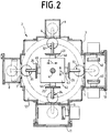
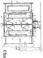
- the vacuum treatment device essentially from a frame-shaped Side part 3 with a total of four openings 4 to 7, the four box-shaped treatment chambers, one to close the side part 3 down Vacuum chamber base plate 12, a not shown the side part 3 to be closed upwards Vacuum chamber cover in the bottom plate 12 and the chamber lid rotatable and mounted vertically Shaft 14 with attached to it star-shaped horizontally extending arms 15 to 18, the articulated with the arms 15 to 18 Tension / compression struts 19 to 22, the respective Treatment chambers 8 to 11 associated with the ends of the struts 19 to 22 articulated Locking plates 23 to 26 with the on them attached substrate carriers, one with the shaft 14 rotatably connected guide plate 27 with these attached pairs of rails 28 to 31 for Holding and guiding the closure plates 23 to 26 and those in the four treatment chambers 8 to 11 arranged - and not shown in detail - coating tools, such as B. glow and sputter cathodes 41.42.
- the main chamber 2 and the associated treatment chambers 8 to 11 be evacuated. Will the shaft 14 now stationary guide plate 27 rotated by about 90 ° - counter clockwise - then move all four closure plates 23 to 26 radially to the outside and the openings 4 to 7 are from closed this.
- the editing tools e.g. B. the cathodes 41,42 takes place now the treatment of the substrates. If in different types of tools in the treatment chambers are arranged, each substrate of the In turn in each of the four treatment chambers 8 promoted to 11 and there in the desired order be treated.
- the removal of the Substrates 36 to 39 can be used after treatment done in the same way as the assembly took place.
- the vacuum treatment device 2 is in place of a shaft 14th with arms 15 to 18 with articulated on them Thrust / pressure struts 19 to 22 with the shaft 41 Housing rotatably mounted on the base plate 12 42 with four held and guided in it Booms 43 to 46 are provided.
- This boom 43 to 46 are opposite the housing 42 in the direction the arrows E and F telescopic so that the attached the free ends of the arms 43 to 46 Locking plates 23 to 26 in front of the openings 4 to 7 or in that shown in the drawing Starting position are movable.
- the embodiment of the vacuum treatment device 3 instead of a shaft 14 a screw 47 on the with nuts 48.49 interacts, the parts of on the Screw-guided yokes are 50.51.
- a synchronous rotary movement of the guide plate 27 and shaft 14.41 or screw 47 has for Consequence that all closure plates 23 to 26 at the same time along with those held by them Substrates 36 to 39 in the direction of the arrow, d. H. from who moves one to the next treatment station are - provided the closure plates 23 to 26 have previously been moved to their starting position been-.
Landscapes
- Chemical & Material Sciences (AREA)
- Chemical Kinetics & Catalysis (AREA)
- Engineering & Computer Science (AREA)
- Materials Engineering (AREA)
- Mechanical Engineering (AREA)
- Metallurgy (AREA)
- Organic Chemistry (AREA)
- Physical Vapour Deposition (AREA)
- Catching Or Destruction (AREA)
Applications Claiming Priority (2)
| Application Number | Priority Date | Filing Date | Title |
|---|---|---|---|
| DE19715245A DE19715245C2 (de) | 1997-04-12 | 1997-04-12 | Vakuumbehandlungsvorrichtung zum Aufbringen dünner Schichten |
| DE19715245 | 1997-04-12 |
Publications (2)
| Publication Number | Publication Date |
|---|---|
| EP0872573A1 true EP0872573A1 (fr) | 1998-10-21 |
| EP0872573B1 EP0872573B1 (fr) | 2001-12-05 |
Family
ID=7826287
Family Applications (1)
| Application Number | Title | Priority Date | Filing Date |
|---|---|---|---|
| EP98105913A Expired - Lifetime EP0872573B1 (fr) | 1997-04-12 | 1998-04-01 | Dispositif de traitement sous vide de dépôt de couches minces |
Country Status (8)
| Country | Link |
|---|---|
| US (1) | US5993556A (fr) |
| EP (1) | EP0872573B1 (fr) |
| JP (1) | JP4149026B2 (fr) |
| CN (1) | CN1093888C (fr) |
| CA (1) | CA2234351C (fr) |
| DE (2) | DE19715245C2 (fr) |
| ES (1) | ES2167820T3 (fr) |
| TW (1) | TW428038B (fr) |
Families Citing this family (17)
| Publication number | Priority date | Publication date | Assignee | Title |
|---|---|---|---|---|
| US6162299A (en) | 1998-07-10 | 2000-12-19 | Asm America, Inc. | Multi-position load lock chamber |
| DE10102991C2 (de) * | 2000-02-19 | 2003-11-20 | Ald Vacuum Techn Ag | Einrichtung zum Aufheizen eines Werkstücks aus Metall |
| DE10064237A1 (de) * | 2000-12-22 | 2002-07-04 | Volkswagen Ag | Radarradom zum Schutz von Radarstrahlern |
| JP4515630B2 (ja) * | 2000-12-28 | 2010-08-04 | 芝浦メカトロニクス株式会社 | 真空処理装置 |
| US6802935B2 (en) * | 2002-03-21 | 2004-10-12 | Taiwan Semiconductor Manufacturing Co., Ltd | Semiconductor chamber process apparatus and method |
| US6858085B1 (en) * | 2002-08-06 | 2005-02-22 | Tegal Corporation | Two-compartment chamber for sequential processing |
| US7800933B2 (en) * | 2005-09-28 | 2010-09-21 | Sandisk 3D Llc | Method for using a memory cell comprising switchable semiconductor memory element with trimmable resistance |
| ATE343220T1 (de) | 2004-05-28 | 2006-11-15 | Applied Films Gmbh & Co Kg | Antriebsmechanismus für eine vakuum- behandlungsanlage |
| US20110165997A1 (en) * | 2008-08-22 | 2011-07-07 | Alton Reich | Rotary exercise equipment apparatus and method of use thereof |
| US9272186B2 (en) | 2008-08-22 | 2016-03-01 | Alton Reich | Remote adaptive motor resistance training exercise apparatus and method of use thereof |
| US9144709B2 (en) | 2008-08-22 | 2015-09-29 | Alton Reich | Adaptive motor resistance video game exercise apparatus and method of use thereof |
| US8807318B2 (en) * | 2011-09-20 | 2014-08-19 | International Business Machines Corporation | Multi-generational carrier platform |
| DE102017223078A1 (de) * | 2017-12-18 | 2019-06-19 | Krones Ag | Vorrichtung zum Behandeln von Behältern |
| CN108315706A (zh) * | 2018-04-02 | 2018-07-24 | 上海应用技术大学 | 一种对刀具进行pvd涂层的真空镀膜装置 |
| TWI896881B (zh) * | 2022-06-08 | 2025-09-11 | 凌嘉科技股份有限公司 | 並列式鍍膜設備及多層膜的鍍膜方法 |
| CN115613131B (zh) * | 2022-10-17 | 2023-11-28 | 江苏汉印机电科技股份有限公司 | 一种碳化硅外延化学气相沉积系统的真空腔室 |
| CN118703953B (zh) * | 2024-06-13 | 2025-05-27 | 山东贝迪思真空科技有限公司 | 一种半导体材料用真空镀膜机 |
Citations (1)
| Publication number | Priority date | Publication date | Assignee | Title |
|---|---|---|---|---|
| EP0737998A2 (fr) * | 1995-04-11 | 1996-10-16 | Balzers und Leybold Deutschland Holding Aktiengesellschaft | Dispositif de dépÔt de couches minces sur un substrat |
Family Cites Families (6)
| Publication number | Priority date | Publication date | Assignee | Title |
|---|---|---|---|---|
| DE2848480C2 (de) * | 1978-11-08 | 1984-11-08 | Siemens AG, 1000 Berlin und 8000 München | Vorrichtung zum Aufbringen von Schichten auf Träger unter Vakuum |
| US5292393A (en) * | 1986-12-19 | 1994-03-08 | Applied Materials, Inc. | Multichamber integrated process system |
| JP2598353B2 (ja) * | 1991-12-04 | 1997-04-09 | アネルバ株式会社 | 基板処理装置、基板搬送装置及び基板交換方法 |
| EP0555764B1 (fr) * | 1992-02-12 | 1997-06-11 | Balzers Aktiengesellschaft | Appareillage de traitement sous vide |
| US5709785A (en) * | 1995-06-08 | 1998-01-20 | First Light Technology Inc. | Metallizing machine |
| US5855681A (en) * | 1996-11-18 | 1999-01-05 | Applied Materials, Inc. | Ultra high throughput wafer vacuum processing system |
-
1997
- 1997-04-12 DE DE19715245A patent/DE19715245C2/de not_active Expired - Fee Related
-
1998
- 1998-04-01 EP EP98105913A patent/EP0872573B1/fr not_active Expired - Lifetime
- 1998-04-01 ES ES98105913T patent/ES2167820T3/es not_active Expired - Lifetime
- 1998-04-01 DE DE59802288T patent/DE59802288D1/de not_active Expired - Lifetime
- 1998-04-08 CA CA002234351A patent/CA2234351C/fr not_active Expired - Fee Related
- 1998-04-09 CN CN98109736A patent/CN1093888C/zh not_active Expired - Fee Related
- 1998-04-09 US US09/057,551 patent/US5993556A/en not_active Expired - Fee Related
- 1998-04-09 JP JP09702798A patent/JP4149026B2/ja not_active Expired - Fee Related
- 1998-04-10 TW TW087105438A patent/TW428038B/zh not_active IP Right Cessation
Patent Citations (1)
| Publication number | Priority date | Publication date | Assignee | Title |
|---|---|---|---|---|
| EP0737998A2 (fr) * | 1995-04-11 | 1996-10-16 | Balzers und Leybold Deutschland Holding Aktiengesellschaft | Dispositif de dépÔt de couches minces sur un substrat |
Also Published As
| Publication number | Publication date |
|---|---|
| CN1201720A (zh) | 1998-12-16 |
| CN1093888C (zh) | 2002-11-06 |
| ES2167820T3 (es) | 2002-05-16 |
| EP0872573B1 (fr) | 2001-12-05 |
| CA2234351C (fr) | 2002-02-05 |
| DE19715245C2 (de) | 1999-09-02 |
| DE59802288D1 (de) | 2002-01-17 |
| TW428038B (en) | 2001-04-01 |
| DE19715245A1 (de) | 1998-10-15 |
| JP4149026B2 (ja) | 2008-09-10 |
| CA2234351A1 (fr) | 1998-10-12 |
| US5993556A (en) | 1999-11-30 |
| JPH10280131A (ja) | 1998-10-20 |
Similar Documents
| Publication | Publication Date | Title |
|---|---|---|
| EP0872573B1 (fr) | Dispositif de traitement sous vide de dépôt de couches minces | |
| DE102007030955B4 (de) | Verfahren und Vorrichtung zum Bearbeiten von um eine Werkstückachse rotierenden Werkstücken | |
| EP0312694B1 (fr) | Appareil suivant le principe à carrousel pour revêtir des substrats | |
| EP0672595B1 (fr) | Dispositif pour le transport de substrats | |
| DE4009603A1 (de) | Vorrichtung zum ein- und ausschleusen eines werkstuecks in eine vakuumkammer | |
| EP3456466B1 (fr) | Magasin à outils et procédé de changement d'outils | |
| DE8417022U1 (de) | Drehtisch-Bearbeitungsvorrichtung | |
| DE4235676C2 (de) | Vakuumkammer zum Transport scheibenförmiger Werkstücke in einer Vakuumanlage | |
| EP0461293A1 (fr) | Procédé de galetage respectivement écrouissage de vilebrequins à excentricité différente et machine pour la mise en oeuvre de ce procédé | |
| DE19500652C1 (de) | Handhabungsvorrichtung für eine Werkzeugmaschine | |
| DE3408734A1 (de) | Einrichtung zum einwechseln von werkzeugen oder dgl. in die arbeitsspindel einer werkzeugmaschine | |
| DE3317554A1 (de) | Bearbeitungszentrum | |
| EP0564842A1 (fr) | Machine-outil avec table tournante | |
| DE10025614A1 (de) | Vorrichtung zum Greifen und Transportieren von Werkstücken in Drehmaschinen | |
| EP0609488A1 (fr) | Appareil pour faire entrer et/ou sortir un masque respectivement dans ou hors de la chambre d'un dispositif de revêtement sous vide | |
| EP0858948B1 (fr) | Machine d'emballage, en particulier pour la production de paquets de cigarettes | |
| EP0860259A2 (fr) | Installation pour transporter des substrats | |
| EP1194266B1 (fr) | Dispositif de changement d'outil destine a une machine-outil | |
| EP1243529B1 (fr) | Dispositif d'approvisionnement et/ou d'évacuation de magasins remplis d'objets | |
| EP0481276B1 (fr) | Machine-outil | |
| DE10058627A1 (de) | Drehmaschine | |
| DE2457859A1 (de) | Vorrichtung zum erfassen und freigeben von werkstuecken | |
| EP0283810B1 (fr) | Presse transfert | |
| CH691377A5 (de) | Kammeranordnung für den Transport von Werkstücken und deren Verwendung. | |
| WO1988001564A1 (fr) | Systeme de manipulation et de transport d'ebauches de disques compacts ou similaire |
Legal Events
| Date | Code | Title | Description |
|---|---|---|---|
| PUAI | Public reference made under article 153(3) epc to a published international application that has entered the european phase |
Free format text: ORIGINAL CODE: 0009012 |
|
| AK | Designated contracting states |
Kind code of ref document: A1 Designated state(s): CH DE ES FR GB IT LI NL PT |
|
| AX | Request for extension of the european patent |
Free format text: AL;LT;LV;MK;RO;SI |
|
| 17P | Request for examination filed |
Effective date: 19981105 |
|
| RIN1 | Information on inventor provided before grant (corrected) |
Inventor name: HEINRICH, JUERGEN Inventor name: BEUL, JOHANNES Inventor name: KUNKEL, STEFAN Inventor name: SCHUESSLER, HANS Inventor name: MAIDHOF, HANS |
|
| AKX | Designation fees paid |
Free format text: CH DE ES FR GB IT LI NL PT |
|
| GRAG | Despatch of communication of intention to grant |
Free format text: ORIGINAL CODE: EPIDOS AGRA |
|
| 17Q | First examination report despatched |
Effective date: 20010119 |
|
| GRAG | Despatch of communication of intention to grant |
Free format text: ORIGINAL CODE: EPIDOS AGRA |
|
| GRAH | Despatch of communication of intention to grant a patent |
Free format text: ORIGINAL CODE: EPIDOS IGRA |
|
| RAP1 | Party data changed (applicant data changed or rights of an application transferred) |
Owner name: UNAXIS TRADING AG |
|
| GRAH | Despatch of communication of intention to grant a patent |
Free format text: ORIGINAL CODE: EPIDOS IGRA |
|
| GRAA | (expected) grant |
Free format text: ORIGINAL CODE: 0009210 |
|
| AK | Designated contracting states |
Kind code of ref document: B1 Designated state(s): CH DE ES FR GB IT LI NL PT |
|
| REG | Reference to a national code |
Ref country code: CH Ref legal event code: EP |
|
| REG | Reference to a national code |
Ref country code: GB Ref legal event code: IF02 |
|
| REF | Corresponds to: |
Ref document number: 59802288 Country of ref document: DE Date of ref document: 20020117 |
|
| PG25 | Lapsed in a contracting state [announced via postgrant information from national office to epo] |
Ref country code: PT Free format text: LAPSE BECAUSE OF FAILURE TO SUBMIT A TRANSLATION OF THE DESCRIPTION OR TO PAY THE FEE WITHIN THE PRESCRIBED TIME-LIMIT Effective date: 20020305 |
|
| GBT | Gb: translation of ep patent filed (gb section 77(6)(a)/1977) |
Effective date: 20020214 |
|
| ET | Fr: translation filed | ||
| REG | Reference to a national code |
Ref country code: ES Ref legal event code: FG2A Ref document number: 2167820 Country of ref document: ES Kind code of ref document: T3 |
|
| PLBE | No opposition filed within time limit |
Free format text: ORIGINAL CODE: 0009261 |
|
| STAA | Information on the status of an ep patent application or granted ep patent |
Free format text: STATUS: NO OPPOSITION FILED WITHIN TIME LIMIT |
|
| 26N | No opposition filed | ||
| REG | Reference to a national code |
Ref country code: CH Ref legal event code: PFA Owner name: OERLIKON TRADING AG, TRUEBBACH Free format text: UNAXIS TRADING AG# #9477 TRUEBBACH (CH) -TRANSFER TO- OERLIKON TRADING AG, TRUEBBACH#HAUPTSTRASSE#9477 TRUEBBACH (CH) |
|
| PGFP | Annual fee paid to national office [announced via postgrant information from national office to epo] |
Ref country code: FR Payment date: 20100506 Year of fee payment: 13 Ref country code: ES Payment date: 20100427 Year of fee payment: 13 |
|
| PGFP | Annual fee paid to national office [announced via postgrant information from national office to epo] |
Ref country code: NL Payment date: 20100413 Year of fee payment: 13 Ref country code: IT Payment date: 20100427 Year of fee payment: 13 Ref country code: DE Payment date: 20100423 Year of fee payment: 13 |
|
| PGFP | Annual fee paid to national office [announced via postgrant information from national office to epo] |
Ref country code: CH Payment date: 20100423 Year of fee payment: 13 |
|
| PGFP | Annual fee paid to national office [announced via postgrant information from national office to epo] |
Ref country code: GB Payment date: 20100420 Year of fee payment: 13 |
|
| REG | Reference to a national code |
Ref country code: DE Ref legal event code: R119 Ref document number: 59802288 Country of ref document: DE |
|
| REG | Reference to a national code |
Ref country code: DE Ref legal event code: R119 Ref document number: 59802288 Country of ref document: DE |
|
| REG | Reference to a national code |
Ref country code: NL Ref legal event code: V1 Effective date: 20111101 |
|
| REG | Reference to a national code |
Ref country code: CH Ref legal event code: PL |
|
| GBPC | Gb: european patent ceased through non-payment of renewal fee |
Effective date: 20110401 |
|
| REG | Reference to a national code |
Ref country code: FR Ref legal event code: ST Effective date: 20111230 |
|
| PG25 | Lapsed in a contracting state [announced via postgrant information from national office to epo] |
Ref country code: CH Free format text: LAPSE BECAUSE OF NON-PAYMENT OF DUE FEES Effective date: 20110430 Ref country code: LI Free format text: LAPSE BECAUSE OF NON-PAYMENT OF DUE FEES Effective date: 20110430 Ref country code: FR Free format text: LAPSE BECAUSE OF NON-PAYMENT OF DUE FEES Effective date: 20110502 Ref country code: NL Free format text: LAPSE BECAUSE OF NON-PAYMENT OF DUE FEES Effective date: 20111101 |
|
| PG25 | Lapsed in a contracting state [announced via postgrant information from national office to epo] |
Ref country code: IT Free format text: LAPSE BECAUSE OF NON-PAYMENT OF DUE FEES Effective date: 20110401 Ref country code: GB Free format text: LAPSE BECAUSE OF NON-PAYMENT OF DUE FEES Effective date: 20110401 |
|
| REG | Reference to a national code |
Ref country code: ES Ref legal event code: FD2A Effective date: 20120524 |
|
| PG25 | Lapsed in a contracting state [announced via postgrant information from national office to epo] |
Ref country code: ES Free format text: LAPSE BECAUSE OF NON-PAYMENT OF DUE FEES Effective date: 20110402 |
|
| PG25 | Lapsed in a contracting state [announced via postgrant information from national office to epo] |
Ref country code: DE Free format text: LAPSE BECAUSE OF NON-PAYMENT OF DUE FEES Effective date: 20111031 |