EP0657260B1 - Procédé pour surveiller et assurer la qualité d'éléments de construction moulés - Google Patents
Procédé pour surveiller et assurer la qualité d'éléments de construction moulés Download PDFInfo
- Publication number
- EP0657260B1 EP0657260B1 EP94119294A EP94119294A EP0657260B1 EP 0657260 B1 EP0657260 B1 EP 0657260B1 EP 94119294 A EP94119294 A EP 94119294A EP 94119294 A EP94119294 A EP 94119294A EP 0657260 B1 EP0657260 B1 EP 0657260B1
- Authority
- EP
- European Patent Office
- Prior art keywords
- measuring arrangement
- freshly made
- batch
- individual
- height
- Prior art date
- Legal status (The legal status is an assumption and is not a legal conclusion. Google has not performed a legal analysis and makes no representation as to the accuracy of the status listed.)
- Expired - Lifetime
Links
Images
Classifications
-
- B—PERFORMING OPERATIONS; TRANSPORTING
- B28—WORKING CEMENT, CLAY, OR STONE
- B28B—SHAPING CLAY OR OTHER CERAMIC COMPOSITIONS; SHAPING SLAG; SHAPING MIXTURES CONTAINING CEMENTITIOUS MATERIAL, e.g. PLASTER
- B28B17/00—Details of, or accessories for, apparatus for shaping the material; Auxiliary measures taken in connection with such shaping
- B28B17/0063—Control arrangements
- B28B17/0072—Product control or inspection
-
- G—PHYSICS
- G01—MEASURING; TESTING
- G01B—MEASURING LENGTH, THICKNESS OR SIMILAR LINEAR DIMENSIONS; MEASURING ANGLES; MEASURING AREAS; MEASURING IRREGULARITIES OF SURFACES OR CONTOURS
- G01B11/00—Measuring arrangements characterised by the use of optical techniques
- G01B11/02—Measuring arrangements characterised by the use of optical techniques for measuring length, width or thickness
- G01B11/024—Measuring arrangements characterised by the use of optical techniques for measuring length, width or thickness by means of diode-array scanning
Definitions
- the invention relates to a method for quality assurance or Quality monitoring of shaped components such as shaped blocks, concrete blocks, Paving stones, bricks, slabs or the like, which in one Molding device can be manufactured continuously and in batches transported to a warehouse by means of a conveyor for tying are, a measuring arrangement directly downstream of the molding device is the individual moldings in a batch Measurements are carried out, the moldings being over or under a predetermined target value, immediately after passing through the Sorted measuring arrangement and fed back to the molding device are used, and the measuring arrangement for controlling the molding device can be.
- a mixture of sand and / or gravel, cement and water or others Base materials mixed with binders this mixture then a jogger and press for molding the molding is fed.
- the mixture is poured into a mold and then first shaken in the mold for compaction. After that, the mixture post-pressed in the mold with a press stamp, so that the Pressings remain on a pallet after lifting the mold.
- These compacts are then on the pallet by means of a conveyor drove to a warehouse, where they would then set or dry out to be stored for a certain period of time before they are stored on their Transport location to be used as components.
- the color of such a molding depends on the Basic ingredients also from the pressing or its compression, since with a higher compression or compression of the molding, the pore volume is less in the body and the molding follows its setting or drying time is much brighter, than a not so compacted molding, which due to its lower Compression or compression a much larger pore volume and thus in terms of its color appearance after its setting time appears much darker.
- the machine is designed Laying moldings produced in this way is then extremely problematic if the moldings have different outer contours have and therefore not a grasping of the surface of the pallet is possible. There is a frictional connection between the molded parts then not achieved, since even small tolerance differences lead to that the moldings fall out of the gripper.
- the first document describes one Measuring arrangement, which is connected downstream of a molding device, in particular here shaped blocks, concrete blocks, paving stones, bricks, slabs or the like to measure. Thereby those in a batch are measure individual moldings in such a way that above the moldings two probes are arranged, the distance pad molding on the one hand and, on the other hand, measure the surface molding.
- a corresponding Measurement arrangement is also based on the second document, where the The molding is also electronically measured for its shape becomes.
- a major disadvantage with the prior art previously known devices is that they only Carry out measurements to determine the shape of a molding.
- the invention solves the problem in that with the measuring arrangement in addition to the height measurement a color measurement on individual is carried out in a batch moldings, wherein the color measurement of a high resolution line scan the surface of the individual moldings of a batch according to their color values and their brightness measures.
- the height measurement which one of the measurements carried out on the molding is also an indication of the later appearance of color, because in particular with high compression or compression of the molding, the pore volume is small, which after the setting process turns to a lighter one Color of the product leads.
- breaking strength one can use the method made molded article to this effect be that moldings that have a lower height, due to the higher press pressure thus have a lower porosity, and these products thus formed or shaped from breaking strength deviates from moldings whose porosity is greater. Therefore can also make a statement about this with this measuring arrangement what breaking strengths the individual batches have, so that when monitoring the quality the breaking strength of such Formlings can be monitored with.
- the height measurement is carried out of the individual moldings with at least two installed Laser diodes and a high-resolution line scan camera. Doing so once the height of the pallet on which the batch of moldings is located, measured with one of the two lasers, with the second Laser diode determines the height of the individual stones on the pallet become. The difference in height measurements from pallet and The molded product then gives the exact height of the product. When using of wooden pallets, it can therefore occur that in particular the Wooden pallets of different thicknesses due to abrasion exhibit. It is therefore necessary to determine the reference point in order to be able to carry out exact height measurements that the height the pallet is determined. To do this, use the first laser measured this height of the pallet, and the height with a second laser of the molding. Because of the resulting different two height measurements, can now easily find the exact one The amount of the product itself can be calculated.
- laser diodes can be used additional lasers will be installed, either for height measurement or used to check the shape contours of the molding.
- the contours of the Forms can be recorded, such as angled Side surfaces or indentations in the surface.
- a weight determination of the Batch are made to add an additional one designed for quality To get assessment.
- the conveyor Pressure transducers arranged which are initially the empty weight of the pallet determine, after passing through the molding device, the corresponding Pallet with the overlying moldings recorded by weight becomes. From the difference and the number of moldings then determine the weight of the single molding, which also done by the measuring arrangement.
- the measuring arrangement additionally for height measurement, a color measurement on individual ones in a batch Moldings carried out.
- the color measurement is done with the high resolution line scan camera covering the surface of each molding recognizes a batch according to its color value and its brightness.
- the high-resolution line camera splits it from the surface the surface signal originating from the individual moldings into the signals R (red), G (green) and B (blue) to determine the color value and in Signal Y (luminance) to determine the brightness value.
- the high-resolution line scan camera can be used in parallel with the height and color measurement to detect the surfaces of those in a batch Moldings are used.
- the detection takes place by means of of a high-intensity headlight that is directed to the batch is directed.
- the Kamara takes exactly the light and the darker Areas on, so that the resulting outer contours the surface of the molding can be closed, wherein its standardized surface extension is saved as a setpoint and is used for comparison with the freshly formed batch.
- To the External contours, which are particularly important for mechanical laying are so a grab a batch from the range of below Frictional moldings are made possible, to which the Surface structure of the single molding recognized with the camera and be evaluated.
- All individual measured values of a batch such as height measurement the palette, the individual moldings, as well as the color values and the Brightness values and surface values are fed to a computer and these instantaneous values are then given with predetermined ones in the computer stored setpoints compared.
- the color setpoints are by color calculation of typical color properties of a product determined and compared with previously learned target patterns. Corresponding These target patterns are then displayed on the tolerances brought the downstream "PC”. If the im is exceeded Computer stored for the quality of a batch If setpoints are established, the device switches off immediately remove the not yet set batch from the conveyor, to feed them back to the molding device.
- the Measuring arrangement recorded the measured values transversely to the conveying direction, wherein in each case the moldings lying one behind the other in a batch Pass through the measuring arrangement to be measured.
- One of the individual measured values is used Batch formed an average value that is saved with the specified one Mean value of a target value is compared.
- Corresponding The computer program evaluates these different tolerances Values and puts them on the screen of the downstream "PC's" for display. It turned out to be very simplistic that, for example, different article numbers are the same Target parameters for color, height and area are also saved so that when you enter the article number, these values already with can be saved.
- the measurement program for the camera is from the "PC" started, and with the current parameters of the to be produced Provide shaped stones. It is when setting the target value then an advantage if tolerance limits of plus minus 5% are permitted become.
- the invention is based on a device in which the products can be produced continuously in a molding device by means of a mold and in batches by means of a conveyor for tying be transported to a warehouse. It is according to the invention of particular advantage that immediately behind the molding device a measuring arrangement is arranged above the conveyor, which performs individual moldings in a batch. Due to one provided directly behind the molding device Measuring arrangement is achieved that in particular faulty batches immediately can be sorted out after the exit. Brings to that it has the advantage that these batches not yet set can be added back to the mixture and thus a loss Raw materials is low. Direct sorting after molding also prevents defective products from being delivered and consequently in particular later complaints no longer occur, which can be regarded as very costly in terms of their elimination are.
- the measuring arrangement can also be used for control or regulation serve the device.
- the measuring arrangement consists of at least two laser diodes and a high-resolution line scan camera is arranged on a frame above the conveyor.
- the line scan camera records the height, color and surface of the molded products.
- the line scan camera and the laser diodes on this frame horizontally in different positions slidably arranged.
- the individual Gauges or probes on different products easily and set securely.
- the laser diodes and the line scan camera on sledges arranged by means of a spindle drive on a horizontal extending beams of the frame can be moved.
- One of the two laser beams is on the pallet and the second laser beam is directed onto the moldings lying on top.
- Both the height measurement and the line camera are carried out the color measurement.
- To put higher objects on the conveyor To be able to measure are the height adjustment of the frame vertical supports of the frame in different positions telescopic.
- the measuring arrangement is advantageous using a computer to evaluate the momentary measurement arrangement recorded measured values connected.
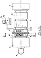
- shaped components such as shaped stones, Concrete blocks, paving stones, bricks, slabs or the like settles the process for manufacturing from the following operating units according to 1, together with a mixer 1 Mixture of sand and / or gravel, cement and water and possibly under Additive still produced additives.
- This mixture made is then fed to a molding device 2, in which then by means of a shape not shown on pallets 3 moldings 4 continuously getting produced.
- a conveyor 5 the molded articles 4 produced in batches are then stored in a warehouse 6 transported where the individual moldings 4 on the pallet 3 for setting be stored.
- a measuring arrangement 7 is connected directly after the shaping device 2, with both height measurements on a batch 8 individual moldings 4 are carried out, as well as a color measurement and a surface measurement on individual ones in a batch 8 Moldings 4 are carried out. They are still not set batches 8, which are above or below a predetermined
- the target value of the measuring arrangement 7 is immediately after passing through the measuring arrangement 7 removed from the flow of the conveyor 5, and the moldings 4 which have not yet set again to the mixing device 1 fed.
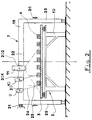
- the height measurement, shown in FIG. 2, of the individual moldings 4 is carried out by means of at least two installed laser diodes 9 and 10 and a high-resolution line camera 11. Regarding the height measurement with one of the laser diodes 9 the height of the pallet 3 determined on which the batch 8 of the moldings 4 is located. With the height of the individual moldings 4 is the second laser diode 9 the pallet 3 measured. The difference resulting from the measurements of pallet 3 and molding 4 then gives the exact amount of Formlings 4. When installing more not shown Laser it is possible to check the contour of the molding 4, for example for qualitative monitoring the side surfaces of a molding 4.
- the color measurement becomes the height measurement with the line camera 11 on the surfaces of the individual moldings 4 of a batch 8 carried out.
- the line camera 11 in particular measures the surfaces according to their color value and their brightness. To do this splits the high resolution line camera 11 that from the surface of each Form stones 4 originating surface signal in the signals R (red), G (green) and B (blue) to determine the color value and into a signal Y (luminance) to determine the brightness value.
- These measured Values of each batch 8 such as height measurement the pallet 3, height measurement of the individual moldings 4, and the Color values and the brightness values are then fed to a computer 12, which then with predetermined stored setpoints of the computer 13 are compared.
- the high-resolution line scan camera can be used in parallel with the height and color measurement 11 for recognizing the surfaces of those in a batch 8 Moldings 4 are used.
- the detection takes place by means of a headlight, not shown, higher Light intensity that is directed to batch 8.
- the Kamara 11 takes exactly the light and the dark areas, so that from it to the resulting outer contours of the surface of the Moldings 4 can be closed, its standardized surface extension is stored as a setpoint and for comparison with the freshly formed batch 8.
- the surface structure can also of the single molding 4 recognized with the camera 11 and be evaluated.
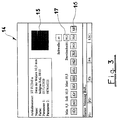
- the surface shown on a screen 14 is designed accordingly, as shown in Figure 3.
- the top left Field contains the article number, the name, the color and additional ones Parameter.
- a map 15 To the right of this is a map 15, in colors become visible similar to a traffic light, so that a Batch 8, which has passed through the measuring arrangement 7 and with the color is rated green, is not sorted out. Accordingly, the Color yellow and red cause the device to stop the corresponding batch 8 can be removed.
- characteristic surfaces 16 are shown, in each of which the one behind the other lying moldings 4 of a batch 8 with the measured heights be made visible. In a single map 17 above the average value given.
- This average is in a tolerance range that does not deviate from the target value by 5%, such as here, for example, when specifying the target value 10 with a deviation of plus minus 0.5, the system is not the computer stopped when, as in map 17, an average value of 10.2 is present.
- the individual measured values as they are the screen area 14 appear, taken transversely to the conveying direction, where each one in a batch 8 in a row Moldings 4 corresponding to the characteristic surfaces 16 when passing through the Measuring arrangement 7 can be measured.
- the measuring arrangement 7 from at least two laser diodes 9 and 10 and a high-resolution line camera 11, which on a frame 18 a conveyor device 19, as shown in particular in FIG. 2 is shown, is arranged.
- the measuring arrangement is located here 7, as already mentioned above, directly behind the molding device 2nd
- the line camera 11 and the laser diodes 9 and 10 are on the frame 18 arranged horizontally in different positions. To fine-tune the different positions the laser diodes 9 and 10 and the line scan camera 11 are located the measuring organs on slide 20, 20.1 and 20.2, which are by means of a separate spindle drive 21 on the horizontal let the extending beam 22 of the frame 18 move.
- the laser diodes 9 and 10 and the line camera 11 are on the individual Slide 20, 20.1 and 20.2 pivoted so that the individual Measuring organs matched to different sizes of moldings 4 can be.
- the laser diodes 9 and 10 and the line camera 11 are in one Level arranged transversely to the conveying direction.
- the swiveling laser diodes 9 and 10 as well as the line camera 11 can be on the respective Carriage 20, 20.1 and 20.2 can be set so that the laser beams 24 at an angle 23 to the objects to be measured, how to hit the pallet 3 and the respective molding 4.
- the laser light spots resulting on the objects, pallet 3 and molding 4 are scanned by the line camera 11, so to speak that instantaneous values can be calculated. It is done with the Line camera 11 both the height measurement and the color measurement, where, as already described in more detail above, the values on a Make the screen visible.
- the vertically extending supports 25 adjusting devices 26 are attached, so that the frame 18 telescopes into different positions can be.
Landscapes
- Chemical & Material Sciences (AREA)
- Engineering & Computer Science (AREA)
- Ceramic Engineering (AREA)
- Mechanical Engineering (AREA)
- Physics & Mathematics (AREA)
- General Physics & Mathematics (AREA)
- Length Measuring Devices By Optical Means (AREA)
- Press-Shaping Or Shaping Using Conveyers (AREA)
- Devices For Post-Treatments, Processing, Supply, Discharge, And Other Processes (AREA)
- Investigating Materials By The Use Of Optical Means Adapted For Particular Applications (AREA)
- Injection Moulding Of Plastics Or The Like (AREA)
Claims (18)
- Procédé pour garantir ou contrôler la qualité de composants moulés tels que des briques moulées, des blocs de béton, des dalles, des tuiles, des plaques ou analogues, qui sont fabriqués de façon continue dans un dispositif de moulage (2) et sont évacués par lots au moyen d'un dispositif de convoyage (5) pour être assemblés selon une couche, dans lequel en aval du dispositif de moulage est branché directement un dispositif de mesure (7), qui exécute des mesures sur les briquettes individuelles (4) situées dans un lot, selon lequel les briquettes (4), qui dépassent par le haut ou par le bas une valeur de consigne prédéterminée, sont extraites par triage directement après avoir traversé le dispositif de mesure et sont renvoyées au dispositif de moulage (2), et le dispositif de mesure (7) peut être utilisé pour régler le dispositif de moulage (2), caractérisé en ce qu'avec le dispositif de mesure (7) on exécuté, en plus d'une mesure de hauteur, une mesure de couleur sur des briquettes individuelles (4) situées dans une charge (8), auquel cas pour la mesure de la couleur, une caméra d'enregistrement ligne par ligne à haute résolution (11) mesure les surfaces des différentes briquettes (4) d'une charge (8) en fonction de leur valeur de couleur et de leur luminosité.
- Procédé selon la revendication 1, caractérisé en ce qu'avec le dispositif de mesure (7) la mesure de hauteur des briquettes (4) est réalisée à l'aide d'au moins deux diodes laser installées (9) et (10) en liaison avec une caméra d'enregistrement ligne par ligne à haute résolution (11).
- Procédé selon l'une des revendications 1 et 2, caractérisé en ce que la hauteur de la palette (3), sur laquelle est située la charge (8), est mesurée à l'aide de la diode laser (9), et les hauteurs des différentes briquettes (4) sont déterminées à l'aide de la diode laser (10) de sorte que la hauteur de la briquette est déterminée au moyen de la différence, que l'on obtient, entre les mesures de hauteur de la palette (3) et de la briquette (4).
- Procédé selon les revendications 2 et 3, caractérisé en ce qu'en plus des diodes laser (9) et (10) on peut installer des lasers supplémentaires, qui sont utilisés soit pour la mesure de hauteur, soit pour le contrôle des contours de la briquette (4).
- Procédé selon la revendication 4, caractérisé en ce que la caméra d'enregistrement ligne par ligne à haute résolution (11) décompose le signal de surface, qui provient de la surface des différentes briquettes (4), en les signaux R (rouge), G (vert) et a (bleu) pour la détermination de la valeur de couleur et en un signal Y (luminance) pour la détermination de la valeur de luminosité.
- Procédé selon les revendications 2 et 5, caractérisé en ce que parallèlement à la mesure de hauteur et de couleur, la caméra d'enregistrement ligne par ligne à haute résolution (11) est utilisée pour identifier les surfaces des briquettes (4) situées dans une charge (8).
- Procédé selon l'une des revendications précédentes 1 à 6, caractérisé en ce que toutes les valeurs mesurées Individuellement d'une charge (8) comme la mesure de hauteur de la palette (3), des différentes briquettes (4), ainsi que les valeurs de couleur, les valeurs de luminosité, les valeurs de surface sont envoyées à un ordinateur (12) et que ces valeurs instantanées sont comparées à des valeurs de consigne prédéterminées mémorisées (17).
- Procédé selon la revendication 7, caractérisé en ce que dans le cas où des valeurs de consigne, qui sont mémorisées dans l'ordinateur (12) et sont déterminantes pour la qualité d'une charge (8), sont dépassées par des valeurs supérieures, le dispositif est immédiatement arrêté de manière à retirer du dispositif de convoyage (5) la charge (8) non encore assemblée et que cette charge est à nouveau envoyée au dispositif de moulage (2).
- Procédé selon une ou plusieurs des revendications 1 à 8, caractérisé en ce qu'à l'aide du dispositif de mesure (7) on enregistre les valeurs de mesure transversalement par rapport à la direction de convoyage, les briquettes (4) situées les unes derrière les autres dans une charge (8) étant respectivement mesurées lorsqu' elles traversent le dispositif de mesure (7).
- Procédé selon la revendication 9, caractérisé en ce qu'une valeur moyenne (17) des différentes valeurs de mesure (7) d'une charge (8) est formée, cette valeur moyenne étant comparée à une valeur de consigne prédéterminée mémorisée.
- Procédé selon la revendication 10, caractérisé en ce que dans la détermination de la valeur de consigne, des limites de tolérance de plus/moins 5 % sont autorisées.
- Dispositif pour la mise en oeuvre du procédé selon l'une des revendications 1 à 11, pour garantir ou contrôler la qualité de composants moulés tels que des briques moulées, des blocs de béton, des dalles, des tuiles, des plaques ou analogues, qui sont fabriqués de façon continue dans un dispositif de moulage (2) et sont évacués par lots au moyen d'un dispositif de convoyage (5) pour être assemblés selon une couche, dans lequel en aval du dispositif de moulage est branché directement un dispositif de mesure (7), qui exécute des mesures sur les briquettes individuelles (4) situées dans un lot, caractérisé en ce que le dispositif de mesure (7) se compose d'au moins deux diodes laser (9, 10) et d'une caméra d'enregistrement ligne par ligne à haute résolution (11), qui est disposée sur un châssis (18) audessus du dispositif de convoyage (5).
- Dispositif selon la revendication 12, caractérisé en ce que la mesure de la couleur des briquettes (4) est également réalisée, après la mise en oeuvre du procédé, à l'aide de la caméra d'enregistrement ligne par ligne (11), en plus de la mesure de hauteur.
- Dispositif selon la revendication 13, caractérisé en ce que la caméra d'enregistrement ligne par ligne (11) et les diodes laser (9, 10) sont disposées sur le châssis (18) de manière à être déplaçables horizontalement dans différentes positions.
- Dispositif selon la revendication 14, caractérisé en ce que pour le réglage précis des différents positionnements, les diodes laser (9, 10) et la caméra d'enregistrement ligne par ligne (11) sont disposées sur des chariots (20, 20.1 et 20.2), qui sont disposés de manière à être déplaçables, au moyen d'un dispositif d'entraínement à broche (21), sur une poutre horizontale (22) du châssis (18).
- Dispositif selon les revendications 12 à 15, caractérisé en ce que les diodes laser (9, 10) et la caméra d'enregistrement ligne par ligne (11) sont disposées dans un plan transversal par rapport à la direction de convoyage, les différentes diodes laser (9) et (10) étant disposées sous un angle (23) transversalement par rapport à la direction de convoyage de telle sorte que les faisceaux laser (24) rencontrent les briquettes (3, 4) à mesurer, conformément à leur réglage angulaire.
- Dispositif selon la revendication 16, caractérisé en ce qu'un faisceau laser (24) est dirigé sur la palette (3) et que le second faisceau laser (24a) est dirigé sur les briquettes (4) situées sur la palette.
- Dispositif selon une ou plusieurs des revendications précédentes 12 à 17, caractérisé en ce que le dispositif de mesure (7) est relié à un ordinateur (12) pour l'évaluation des valeurs de mesure enregistrées instantanément par le dispositif de mesure (7).
Applications Claiming Priority (2)
| Application Number | Priority Date | Filing Date | Title |
|---|---|---|---|
| DE4341894A DE4341894C1 (de) | 1993-12-08 | 1993-12-08 | Verfahren zur Qualitätssicherung bzw. zur Qualitätsüberwachung von aus Beton hergestellten Produkten |
| DE4341894 | 1993-12-08 |
Publications (2)
| Publication Number | Publication Date |
|---|---|
| EP0657260A1 EP0657260A1 (fr) | 1995-06-14 |
| EP0657260B1 true EP0657260B1 (fr) | 1999-02-10 |
Family
ID=6504506
Family Applications (1)
| Application Number | Title | Priority Date | Filing Date |
|---|---|---|---|
| EP94119294A Expired - Lifetime EP0657260B1 (fr) | 1993-12-08 | 1994-12-07 | Procédé pour surveiller et assurer la qualité d'éléments de construction moulés |
Country Status (3)
| Country | Link |
|---|---|
| EP (1) | EP0657260B1 (fr) |
| AT (1) | ATE176617T1 (fr) |
| DE (2) | DE4341894C1 (fr) |
Cited By (2)
| Publication number | Priority date | Publication date | Assignee | Title |
|---|---|---|---|---|
| CN106269557A (zh) * | 2016-08-31 | 2017-01-04 | 重庆市扬昇药业有限公司 | 黑膏药次品分选机 |
| CN111890541A (zh) * | 2020-07-06 | 2020-11-06 | 北新集团建材股份有限公司 | 一种石膏板立边直角度高精度自动调整装置 |
Families Citing this family (14)
| Publication number | Priority date | Publication date | Assignee | Title |
|---|---|---|---|---|
| DE19527147A1 (de) * | 1994-10-10 | 1996-04-11 | Laeis & Bucher Gmbh | Verfahren und Vorrichtung zur Qualitätsprüfung von Formteilen |
| US5766538A (en) * | 1995-03-28 | 1998-06-16 | Masa Aktiengesellschaft | Method of quality control during production of concrete blocks |
| DE19638065A1 (de) * | 1996-09-18 | 1998-03-19 | Massen Machine Vision Systems | Automatische Qualitätskontrolle von Fliesen |
| DE29702402U1 (de) * | 1997-02-12 | 1997-04-10 | ELSAT Elektroanlagen GmbH, 26683 Saterland | Einrichtung zur Qualitätsprüfung von Formkörpern, insbesondere Betonsteinen |
| DE10055099C2 (de) * | 2000-11-07 | 2002-11-14 | Dyckerhoff Ag | Verfahren zur zerstörungsfreien, automatisierten Festigkeitsbestimmung an Prüfkörpern sowie Prüfvorrichtung zur zerstörungsfreien Festigkeitsbestimmung |
| DE10060903C2 (de) * | 2000-12-07 | 2002-10-31 | Moba Mobile Automation Gmbh | Laser-Höhenregeleinrichtung für eine Baumaschine |
| DE20112088U1 (de) | 2001-07-18 | 2002-01-03 | ViALUX Messtechnik + Bildverarbeitung GmbH, 09126 Chemnitz | Vorrichtung zur Betonsteinprüfung |
| US7862763B2 (en) | 2005-06-23 | 2011-01-04 | Anchor Wall Systems, Inc. | Methods of quality control in concrete block production |
| EP2082684B1 (fr) | 2008-01-25 | 2009-12-16 | Ela Medical | Dispositif médical implantable actif comprenant des moyens de communication bidirectionnelle entre en générateur et des capteurs ou actionneurs situés en extrémité de sonde |
| US9745222B2 (en) | 2015-07-23 | 2017-08-29 | United States Gypsum Company | Apparatus and methods for producing gypsum wallboard |
| EP3770547B1 (fr) | 2019-07-26 | 2022-02-23 | R&W Industrieautomation GmbH | Dispositif d'analyse de pierre et procédé d'évaluation de pierres |
| CN114888944B (zh) * | 2022-05-05 | 2026-02-17 | 浙江康斯迪冶金科技有限公司 | 一种镁碳砖的自动化生产装置 |
| DE102023113821A1 (de) * | 2023-05-25 | 2024-11-28 | ibea Ingenieurbüro für Elektronik und Automatisation GmbH | Inspektionsvorrichtung für Baustoffe und Verfahren zur Inspektion von Baustoffen |
| EP4603248A1 (fr) * | 2024-02-15 | 2025-08-20 | OMAG Maschinenbau GmbH | Procédé de détection d'une unité de produit et dispositif de détection de produit |
Family Cites Families (14)
| Publication number | Priority date | Publication date | Assignee | Title |
|---|---|---|---|---|
| US3109927A (en) * | 1961-04-20 | 1963-11-05 | Florida Tile Ind Inc | Tile size responsive apparatus and control |
| GB1271270A (en) * | 1969-12-11 | 1972-04-19 | Boulton Ltd William | Improvements relating to the manufacture of ceramic articles |
| US4095925A (en) * | 1974-06-03 | 1978-06-20 | Besser Company | Cementitious product making system with product height gauging mechanism |
| DE3539549A1 (de) * | 1985-02-13 | 1987-05-14 | Meindl Josef Ohg | Verfahren und vorrichtung zum pruefen und aussortieren von ziegeln |
| DE3530681A1 (de) * | 1985-08-28 | 1987-03-05 | Passavant Werke | Verfahren und vorrichtung zur erzeugung von formlingen gleichbleibender rohdichte und abmessungen |
| FR2591934A1 (fr) * | 1985-12-19 | 1987-06-26 | Lepreux Joel | Dispositif pour recuperer les blocs en beton defectueux |
| DE3628757A1 (de) * | 1986-08-23 | 1988-03-03 | Fette Wilhelm Gmbh | Verfahren zur qualitaetssicherung bei der herstellung von tabletten |
| FR2631113B1 (fr) * | 1988-05-03 | 1991-04-12 | Cerib | Ensemble de mesure et de controle de produits frais en beton |
| JPH0676920B2 (ja) * | 1988-08-13 | 1994-09-28 | 東洋インキ製造株式会社 | 着色成形品の色むら評価方法 |
| JPH0765957B2 (ja) * | 1989-04-27 | 1995-07-19 | アイエルビー株式会社 | コンクリート製品の不良品検出装置 |
| JPH03130605A (ja) * | 1989-10-16 | 1991-06-04 | Sumitomo Heavy Ind Ltd | 成形品不良検査装置 |
| JPH054263A (ja) * | 1991-06-25 | 1993-01-14 | Mitsubishi Heavy Ind Ltd | 射出成形品の色斑に基づく品質管理方法 |
| DE4200001A1 (de) * | 1992-01-01 | 1993-07-08 | Robert Prof Dr Ing Massen | Optische klassifikation von pflanzen |
| DE4200801A1 (de) * | 1992-01-15 | 1993-08-19 | Fraunhofer Ges Forschung | Vorrichtung zur durchfuehrung einer qualitaetskontrolle |
-
1993
- 1993-12-08 DE DE4341894A patent/DE4341894C1/de not_active Expired - Fee Related
-
1994
- 1994-12-07 DE DE59407803T patent/DE59407803D1/de not_active Expired - Fee Related
- 1994-12-07 AT AT94119294T patent/ATE176617T1/de not_active IP Right Cessation
- 1994-12-07 EP EP94119294A patent/EP0657260B1/fr not_active Expired - Lifetime
Cited By (3)
| Publication number | Priority date | Publication date | Assignee | Title |
|---|---|---|---|---|
| CN106269557A (zh) * | 2016-08-31 | 2017-01-04 | 重庆市扬昇药业有限公司 | 黑膏药次品分选机 |
| CN106269557B (zh) * | 2016-08-31 | 2018-07-17 | 重庆市扬昇药业有限公司 | 黑膏药次品分选机 |
| CN111890541A (zh) * | 2020-07-06 | 2020-11-06 | 北新集团建材股份有限公司 | 一种石膏板立边直角度高精度自动调整装置 |
Also Published As
| Publication number | Publication date |
|---|---|
| ATE176617T1 (de) | 1999-02-15 |
| DE59407803D1 (de) | 1999-03-25 |
| DE4341894C1 (de) | 1995-07-06 |
| EP0657260A1 (fr) | 1995-06-14 |
Similar Documents
| Publication | Publication Date | Title |
|---|---|---|
| DE4341894C1 (de) | Verfahren zur Qualitätssicherung bzw. zur Qualitätsüberwachung von aus Beton hergestellten Produkten | |
| DE69633256T2 (de) | Verfahren und vorrichtung zum herstellen von mustern in formmaterialien | |
| EP0446693B1 (fr) | Procédé de production de plaques de gypse contenant des fibres, en particulier des panneaux de plancher | |
| EP3770547B1 (fr) | Dispositif d'analyse de pierre et procédé d'évaluation de pierres | |
| DE19527147A1 (de) | Verfahren und Vorrichtung zur Qualitätsprüfung von Formteilen | |
| DE3530681C2 (fr) | ||
| CH683243A5 (de) | Verfahren zur Steuerung und/oder Regelung des Pressvorganges einer Steinpresse. | |
| DE69011924T2 (de) | Vorrichtung zur selbsttätigen Korrektur der Pressdichte bei der Herstellung von Dachziegeln. | |
| DE69513298T2 (de) | Verfahren und vorrichtung zum messen und dossieren von schüttguten, insbesondere zum herstellen von spanplatten mit mineralischem bindemittel | |
| DE19615915C2 (de) | Verfahren zum Überwachen und Steuern der Festigkeit von Betonsteinen bei deren chargenweiser Herstellung | |
| DE69401274T2 (de) | Verbesserungen für eine vorrichtung zum herstellen von dachziegeln | |
| DE19956961B4 (de) | Verfahren zur Kontrolle der Einwirkung von Schwingungen auf die Formgebung und Verdichtung von Betonwaren | |
| EP1800817B1 (fr) | Méthode et dispositif pour le contrôle de la qualité du procédé de production de produits en béton | |
| DE2434603A1 (de) | Vorrichtung zur kontrolle der massund formgenauigkeit, insbesondere plattenfoermiger gegenstaende | |
| DE4109464C2 (de) | Verfahren und Einrichtung zur Überwachung und Steuerung der Dichte und Höhe von ungebrannten Anodenblöcken insbesondere für die Aluminium-Schmelzflußelektrolyse | |
| DE4220646C2 (de) | Verfahren und Vorrichtung zum Füllen von Gießformen mit Gießharz o. dgl. gießfähig flüssigen Medien | |
| EP3225371B1 (fr) | Procede et dispositif destines a doter un produit en beton d'un materiau de revetement | |
| DE2552157C3 (de) | Vorrichtung zum Herstellen von Blöcken aus mit einem hydraulischen Bindemittel, vorzugsweise Zement, versetzten lignozellulosehaltigen Teilchen | |
| DE3837713C2 (fr) | ||
| DE2728181A1 (de) | Verfahren und vorrichtung zur herstellung von probekoerpern aus nichtgiessfaehigen bituminoesen massen | |
| CH668032A5 (en) | Unevenly-pressed ceramic item detection method - measures pressure distribution over surface and compares with desired value | |
| DE1810128A1 (de) | Verfahren und Einrichtung zum Herstellen von Betonelementen insbesondere von Betonpflastersteinen | |
| DE69109007T2 (de) | Anlage mit hoher Produktivität zur Herstellung von Keramikfliesen im allgemeinen. | |
| DE19531469C1 (de) | Verfahren zur Steuerung der Konsistenz einer herzustellenden Betonmischung | |
| DE2907700A1 (de) | Aggregat zum automatischen sortieren gebrannter ziegelsteine |
Legal Events
| Date | Code | Title | Description |
|---|---|---|---|
| PUAI | Public reference made under article 153(3) epc to a published international application that has entered the european phase |
Free format text: ORIGINAL CODE: 0009012 |
|
| AK | Designated contracting states |
Kind code of ref document: A1 Designated state(s): AT BE CH DE DK ES FR GB IT LI NL SE |
|
| RAX | Requested extension states of the european patent have changed |
Free format text: LT;SI |
|
| RBV | Designated contracting states (corrected) |
Designated state(s): AT BE CH DE DK ES FR GB IT LI NL SE |
|
| 17P | Request for examination filed |
Effective date: 19951107 |
|
| 17Q | First examination report despatched |
Effective date: 19970430 |
|
| GRAG | Despatch of communication of intention to grant |
Free format text: ORIGINAL CODE: EPIDOS AGRA |
|
| GRAG | Despatch of communication of intention to grant |
Free format text: ORIGINAL CODE: EPIDOS AGRA |
|
| GRAH | Despatch of communication of intention to grant a patent |
Free format text: ORIGINAL CODE: EPIDOS IGRA |
|
| GRAH | Despatch of communication of intention to grant a patent |
Free format text: ORIGINAL CODE: EPIDOS IGRA |
|
| DAX | Request for extension of the european patent (deleted) | ||
| GRAA | (expected) grant |
Free format text: ORIGINAL CODE: 0009210 |
|
| AK | Designated contracting states |
Kind code of ref document: B1 Designated state(s): AT BE CH DE DK ES FR GB IT LI NL SE |
|
| PG25 | Lapsed in a contracting state [announced via postgrant information from national office to epo] |
Ref country code: SE Free format text: THE PATENT HAS BEEN ANNULLED BY A DECISION OF A NATIONAL AUTHORITY Effective date: 19990210 Ref country code: IT Free format text: LAPSE BECAUSE OF FAILURE TO SUBMIT A TRANSLATION OF THE DESCRIPTION OR TO PAY THE FEE WITHIN THE PRE;WARNING: LAPSES OF ITALIAN PATENTS WITH EFFECTIVE DATE BEFORE 2007 MAY HAVE OCCURRED AT ANY TIME BEFORE 2007. THE CORRECT EFFECTIVE DATE MAY BE DIFFERENT FROM THE ONE RECORDED.SCRIBED TIME-LIMIT Effective date: 19990210 Ref country code: FR Free format text: LAPSE BECAUSE OF FAILURE TO SUBMIT A TRANSLATION OF THE DESCRIPTION OR TO PAY THE FEE WITHIN THE PRESCRIBED TIME-LIMIT Effective date: 19990210 Ref country code: ES Free format text: THE PATENT HAS BEEN ANNULLED BY A DECISION OF A NATIONAL AUTHORITY Effective date: 19990210 |
|
| REF | Corresponds to: |
Ref document number: 176617 Country of ref document: AT Date of ref document: 19990215 Kind code of ref document: T |
|
| REG | Reference to a national code |
Ref country code: CH Ref legal event code: EP |
|
| REF | Corresponds to: |
Ref document number: 59407803 Country of ref document: DE Date of ref document: 19990325 |
|
| REG | Reference to a national code |
Ref country code: CH Ref legal event code: NV Representative=s name: BOVARD AG PATENTANWAELTE |
|
| PG25 | Lapsed in a contracting state [announced via postgrant information from national office to epo] |
Ref country code: DK Free format text: LAPSE BECAUSE OF FAILURE TO SUBMIT A TRANSLATION OF THE DESCRIPTION OR TO PAY THE FEE WITHIN THE PRESCRIBED TIME-LIMIT Effective date: 19990510 |
|
| GBT | Gb: translation of ep patent filed (gb section 77(6)(a)/1977) |
Effective date: 19990416 |
|
| EN | Fr: translation not filed | ||
| PG25 | Lapsed in a contracting state [announced via postgrant information from national office to epo] |
Ref country code: AT Free format text: LAPSE BECAUSE OF NON-PAYMENT OF DUE FEES Effective date: 19991207 |
|
| PLBE | No opposition filed within time limit |
Free format text: ORIGINAL CODE: 0009261 |
|
| STAA | Information on the status of an ep patent application or granted ep patent |
Free format text: STATUS: NO OPPOSITION FILED WITHIN TIME LIMIT |
|
| PGFP | Annual fee paid to national office [announced via postgrant information from national office to epo] |
Ref country code: CH Payment date: 19991213 Year of fee payment: 10 |
|
| PG25 | Lapsed in a contracting state [announced via postgrant information from national office to epo] |
Ref country code: DE Free format text: LAPSE BECAUSE OF NON-PAYMENT OF DUE FEES Effective date: 19991231 Ref country code: BE Free format text: LAPSE BECAUSE OF NON-PAYMENT OF DUE FEES Effective date: 19991231 |
|
| 26N | No opposition filed | ||
| BERE | Be: lapsed |
Owner name: PRO.EFF G.M.B.H. Effective date: 19991231 Owner name: BETONWERK LINTEL G.M.B.H. & CO. K.G. Effective date: 19991231 |
|
| PGFP | Annual fee paid to national office [announced via postgrant information from national office to epo] |
Ref country code: GB Payment date: 20001204 Year of fee payment: 7 |
|
| PGFP | Annual fee paid to national office [announced via postgrant information from national office to epo] |
Ref country code: NL Payment date: 20001231 Year of fee payment: 7 |
|
| PG25 | Lapsed in a contracting state [announced via postgrant information from national office to epo] |
Ref country code: GB Free format text: LAPSE BECAUSE OF NON-PAYMENT OF DUE FEES Effective date: 20011207 |
|
| REG | Reference to a national code |
Ref country code: GB Ref legal event code: IF02 |
|
| PG25 | Lapsed in a contracting state [announced via postgrant information from national office to epo] |
Ref country code: NL Free format text: LAPSE BECAUSE OF NON-PAYMENT OF DUE FEES Effective date: 20020701 |
|
| GBPC | Gb: european patent ceased through non-payment of renewal fee |
Effective date: 20011207 |
|
| NLV4 | Nl: lapsed or anulled due to non-payment of the annual fee |
Effective date: 20020701 |
|
| PG25 | Lapsed in a contracting state [announced via postgrant information from national office to epo] |
Ref country code: LI Free format text: LAPSE BECAUSE OF NON-PAYMENT OF DUE FEES Effective date: 20041231 Ref country code: CH Free format text: LAPSE BECAUSE OF NON-PAYMENT OF DUE FEES Effective date: 20041231 |
|
| REG | Reference to a national code |
Ref country code: CH Ref legal event code: PL |