EP0657271A1 - Vorrichtung zum Auswerfen von Spritzgussteilen - Google Patents
Vorrichtung zum Auswerfen von Spritzgussteilen Download PDFInfo
- Publication number
- EP0657271A1 EP0657271A1 EP94115416A EP94115416A EP0657271A1 EP 0657271 A1 EP0657271 A1 EP 0657271A1 EP 94115416 A EP94115416 A EP 94115416A EP 94115416 A EP94115416 A EP 94115416A EP 0657271 A1 EP0657271 A1 EP 0657271A1
- Authority
- EP
- European Patent Office
- Prior art keywords
- crank
- mold
- crank mechanism
- ejector pin
- lever
- Prior art date
- Legal status (The legal status is an assumption and is not a legal conclusion. Google has not performed a legal analysis and makes no representation as to the accuracy of the status listed.)
- Granted
Links
- 238000002347 injection Methods 0.000 title claims abstract description 11
- 239000007924 injection Substances 0.000 title claims abstract description 11
- 230000005540 biological transmission Effects 0.000 claims description 3
- 230000008878 coupling Effects 0.000 abstract description 2
- 238000010168 coupling process Methods 0.000 abstract description 2
- 238000005859 coupling reaction Methods 0.000 abstract description 2
- 238000001746 injection moulding Methods 0.000 description 4
- 239000000853 adhesive Substances 0.000 description 1
- 230000001070 adhesive effect Effects 0.000 description 1
- 238000000418 atomic force spectrum Methods 0.000 description 1
- 230000001419 dependent effect Effects 0.000 description 1
- 238000000465 moulding Methods 0.000 description 1
- 230000000149 penetrating effect Effects 0.000 description 1
- 230000003252 repetitive effect Effects 0.000 description 1
Images


Classifications
-
- B—PERFORMING OPERATIONS; TRANSPORTING
- B29—WORKING OF PLASTICS; WORKING OF SUBSTANCES IN A PLASTIC STATE IN GENERAL
- B29C—SHAPING OR JOINING OF PLASTICS; SHAPING OF MATERIAL IN A PLASTIC STATE, NOT OTHERWISE PROVIDED FOR; AFTER-TREATMENT OF THE SHAPED PRODUCTS, e.g. REPAIRING
- B29C45/00—Injection moulding, i.e. forcing the required volume of moulding material through a nozzle into a closed mould; Apparatus therefor
- B29C45/17—Component parts, details or accessories; Auxiliary operations
- B29C45/40—Removing or ejecting moulded articles
- B29C45/4005—Ejector constructions; Ejector operating mechanisms
-
- B—PERFORMING OPERATIONS; TRANSPORTING
- B29—WORKING OF PLASTICS; WORKING OF SUBSTANCES IN A PLASTIC STATE IN GENERAL
- B29C—SHAPING OR JOINING OF PLASTICS; SHAPING OF MATERIAL IN A PLASTIC STATE, NOT OTHERWISE PROVIDED FOR; AFTER-TREATMENT OF THE SHAPED PRODUCTS, e.g. REPAIRING
- B29C45/00—Injection moulding, i.e. forcing the required volume of moulding material through a nozzle into a closed mould; Apparatus therefor
- B29C45/17—Component parts, details or accessories; Auxiliary operations
- B29C45/40—Removing or ejecting moulded articles
- B29C45/4005—Ejector constructions; Ejector operating mechanisms
- B29C2045/4047—Ejector constructions; Ejector operating mechanisms driven by a crank or eccentric
Definitions
- the invention relates to a device for ejecting injection molded parts according to the preamble of claim 1.
- Injection molding machines have a fixed platen and a platen that is slidably guided on spars, each for one half of an injection mold, which, in the closed position, enclose the mold cavity for the injection molded parts to be produced.
- the movable platen is moved with the help of this clamping unit, thus moving the injection molding tool into its closed and open positions.
- the clamping unit is used to apply the mold locking pressure.
- the injection molded part produced is pressed out of the mold with the aid of one or more ejectors while the mold is being opened or when the mold is open.
- the crank drive responsible there for the movement of the ejector pin consists of a crank disk which is designed as a gear wheel, the teeth of which mesh with the teeth of two toothed racks, one of which is firmly connected to the movable platen and the other to the fixed platen. If the movable platen is moved with the help of the locking device, this movement is transmitted via the toothed racks to the crank disk, which actuates the ejector pin via the eccentrically arranged lever. This means that the ejector movement is directly coupled to the movement of the platen.
- the invention is therefore based on the object of designing a device of the type mentioned at the outset in such a way that the movement of the ejector pin is decoupled from the movement of the platen, so that product-specific ejection characteristics are possible.
- the invention solves this problem with the aid of the features of the characterizing part of claim 1.
- the ejector device is moved along with the movable platen, but the actual ejector pin movement takes place independently of this.
- the ejection time, the ejector speed and force can therefore be individually adjusted to the part to be demolded via the drive.
- the ejection movement can therefore alternatively begin during the opening movement of the mold or only when the mold is open.
- the speed and force curve can be set in such a way that a large force is exerted on the first millimeters of the travel of the ejector pin at low speed to tear the molding off and then the ejection movement is ended with less effort and greater speed.
- the ejector stroke can also be varied depending on the type of part produced.
- a repeated back and forth movement of the ejector pin in the case of parts that are difficult to demold is very simple with the device according to the invention and, above all, can be implemented in a targeted manner.
- the drive of the device is a servo-electric drive which is freely programmable via the drive unit.
- the power is advantageously transmitted from the engine to the crank mechanism via a gearbox and a clutch.
- crank mechanism A stable design of the crank mechanism according to the invention, which at the same time ensures a completely symmetrical power transmission to the ejector pin, is the subject of claim 5.
- the crank mechanism consists of two crank disks arranged parallel to one another, which can be driven synchronously and between which the the slide sliding lever is mounted.
- crank disks can be designed as gear wheels, the teeth of which mesh with the teeth of one pinion each, which are arranged on the shaft driven by the electric motor.
- a device for ejecting injection molded parts from injection molds is generally provided with the reference number 1. It consists essentially of a cross member 2, more precisely a plate which is connected by two profile webs 3 and 4 to the movable platen 5 of an injection molding machine, the platen 5 being slidably guided on four bars 6 and 7, only two of which are shown is. A clamping unit, not shown, is used for this.
- a half 8 of an injection molding tool is arranged on the side of the mold platen 5 opposite the device 1. Together with this tool half 8, the movable platen 5 is moved by means of the clamping unit onto a fixed platen (also not shown) on which the other half of the tool is arranged.
- ball bushings 10 and 11 are provided which slide on the profile rods 3 and 4.
- the profile bars 3 and 4 are perpendicular to the platen surface and are fastened to the platen 5 by means of bolt screws 12 and 13.
- the carriage 9 has between the ball bushings 10 and 11 a recess 14 in which a bolt 15 is provided which serves as a shaft for one end of a lever 16, the other end of which is mounted on a bolt 17 which is eccentrically on a crank disk 18 is arranged.
- the crank disk 18 is rotatably mounted on a shaft 19 which, as can be seen in FIG. 2, is in turn mounted in bearings 20 in walls 21 of a housing accommodating the device.
- crank disks 18 arranged parallel to one another are provided, which are connected to one another by a further pin 22 in addition to the pin 17, so that no relative movement is possible between the two crank disks.
- Both crank disks 18 are designed as gear wheels, the teeth 24 (which are only indicated) mesh with (also only indicated) teeth 25 of two pinions 26 which are arranged on a drive shaft 27 which, as can be seen from FIGS a clutch 28 is connected to the output shaft of a transmission, not shown in detail, which in turn is operated by an electric servo motor 29.
- the device can be seen most clearly from FIG. 3 in addition to the bolt screws 12 and 13 with the help of the angle plate 30 and the support 31, so that no relative movement is possible between the device 1 and the movable platen 5, the support 31 being the Engine attachment serves.
- the recess 14 in the carriage 9 covers in the direction of the platen 5 from a plate 32 screwed onto the carriage 9, which has a receptacle 33 for an ejector pin 34, which is only indicated by dashed lines and is displaceably guided in a bore penetrating the platen 5 and the mold half 8.
- the operation of the device is as follows: as soon as the molded part is sufficiently firm in the mold, the platen 5 is removed from the fixed platen by means of the clamping unit. Ejector device 1 is activated either now or only when the opening movement has been completed.
- the servo-electric drive moves the ejector pin according to a scheme programmed into the drive unit, in which an ejection parabola is realized which is matched to the part to be removed.
- the ejector pin is moved back and forth several times via its drive.
Landscapes
- Engineering & Computer Science (AREA)
- Manufacturing & Machinery (AREA)
- Mechanical Engineering (AREA)
- Moulds For Moulding Plastics Or The Like (AREA)
Abstract
Description
- Die Erfindung betrifft eine Vorrichtung zum Auswerfen von Spritzgußteilen gemäß dem Oberbegriff des Patentanspruches 1.
- Spritzgießmaschinen weisen eine feststehende und eine auf Holmen verschiebbar geführte Formaufspannplatte für jeweils eine Hälfte eines Spritzgießwerkzeuges auf, die in der Schließstellung das Formnest für die herzustellenden Spritzgußteile einschließen.
- Die bewegliche Formaufspannplatte wird mit Hilfe dieser Schließeinheit verschoben und so das Spitzgußwerkzeug in seine Geschlossen- und seine Öffnungsstellung verfahren. Gleichzeitig dient die Schließeinheit zum Aufbringen des Formzuhaltedrucks.
- Das hergestellte Spritzgußteil wird mit Hilfe eines oder mehrerer Auswerfer während des Öffnens des Formwerkzeugs oder bei geöffnetem Formwerkzeug aus diesem herausgedrückt. Bei schlecht entformbaren Teilen, sei es wegen der komplizierten Formgeometrie, sei es infolge großer Adhäsionskräfte, ist es dabei oft erforderlich, den Auswerfer mehrfach hin- und herzubewegen, um das Teil aus der Form zu lösen. Damit die mitunter empfindlichen Teile dabei keinen Schaden nehmen, muß das Auswerfen behutsam erfolgen.
- Aus der US-PS 4 207 051 ist ein Auswerfer der eingangs genannten Art bekannt. Der dort für die Bewegung des Auswerferstifts verantwortliche Kurbeltrieb besteht aus einer Kurbelscheibe, die als Zahnrad ausgebildet ist, dessen Zähne mit den Zähnen zweier Zahnstangen kämmen, von denen die eine mit der beweglichen Formaufspannplatte und die andere mit der feststehenden Formaufspannplatte fest verbunden ist. Wird die bewegliche Formaufspannplatte mit Hilfe der Schließeinrichtung verfahren, wird diese Bewegung über die Zahnstangen auf die Kurbelscheibe übertragen, die über den exzentrisch auf dieser angeordneten Hebel den Auswerferstift betätigt. Das heißt, daß die Auswerferbewegung direkt mit der Bewegung der Formaufspannplatte gekoppelt ist.
- Es ist daher nicht möglich, unabhängig von der Öffnungs- und Schließbewegung der Form produktspezifische Auswurfparabeln zu verwirklichen. Die starre Kopplung der beiden Bewegungen hat darüber hinaus den Nachteil, daß die Auswerferstifte und die sie antreibenden Kurbeltriebe großen mechanischen Belastungen ausgesetzt sind, insbesondere dann, wenn bei schwer entformbaren Teilen der Auswerfer mehrfach hin- und hergefahren werden muß. Denn diese Wiederholbewegung setzt die Bewegung und damit das teilweise Schließen der Formhälfte voraus, wodurch die Teile beschädigt oder zerstört werden können.
- Der Erfindung liegt daher die Aufgabe zugrunde, eine Vorrichtung der eingangs genannten Art so auszubilden, daß die Bewegung des Auswerferstifts von der Bewegung der Formaufspannplatte entkoppelt ist, so daß produktspezifische Auswurfcharakteristiken möglich sind.
- Die Erfindung löst diese Aufgabe mit Hilfe der Merkmale des kennzeichnenden Teils des Anspruches 1.
- Weitere vorteilhafte Ausgestaltungen der Erfindung sind Gegenstand der Unteransprüche.
- Aufgrund der erfindungsgemäßen Bauart wird die Auswerfervorrichtung zwar mit der beweglichen Formaufspannplatte mitbewegt, die eigentliche Auswerferstiftbewegung erfolgt aber unabhängig hiervon. Der Auswurfzeitpunkt, die Auswerfergeschwindigkeit und - kraft kann daher über den Antrieb individuell auf das zu entformende Teil eingestellt werden. Die Auswurfbewegung kann daher alternativ schon während der Öffnungsbewegung der Form oder erst bei geöffneter Form beginnen. Geschwindigkeits- und Kraftverlauf können so eingestellt sein, daß auf den ersten Millimetern des Fahrweges des Auswerferstifts bei geringer Geschwindigkeit eine große Kraft zum Losreißen des Spritzlings aufgebracht wird und danach bei geringerem Kraftaufwand und größerer Geschwindigkeit die Auswurfbewegung beendet wird.
- Ebenso kann der Auswerferhub je nach Art des hergestellten Teils variiert werden.
- Eine mehrmalige Hin- und Herbewegung des Auswerferstifts bei schlecht entformbaren Teilen ist mit der erfindungsgemäßen Vorrichtung sehr einfach und vor allen Dingen gezielt realisierbar.
- Die oben dargestellten Auswurfcharakteristiken bzw. Auswurfparabeln lassen sich besonders leicht einstellen und verifizieren, wenn gemäß Anspruch 2 der Antrieb der Vorrichtung ein servoelektrischer Antrieb ist, der über die Driveeinheit frei programmierbar ist.
- Dabei wird vorteilhaft die Kraft vom Motor auf den Kurbeltrieb über ein Getriebe und eine Kupplung übertragen.
- Eine stabile Ausführung des erfindungsgemäßen Kurbeltriebs, der gleichzeitig für eine vollkommen symmetrische Kraftübertragung auf den Auswerferstift sorgt, ist Gegenstand des Anspruchs 5. In diesem Anspruch wird vorgeschlagen, daß der Kurbeltrieb aus zwei parallel zueinander angeordneten Kurbelscheiben besteht, die synchron antreibbar sind und zwischen denen der den Schlitten verschiebende Hebel gelagert ist.
- Dabei können die Kurbelscheiben wie bereits aus dem Stand der Technik bekannt als Zahnräder ausgebildet sein, deren Zähne mit den Zähnen von jeweils einem Ritzel kämmen, die auf der durch den Elektromotor angetriebenen Welle angeordnet sind.
- Die Erfindung wird im folgenden anhand von Zeichnungen dargestellt und näher erläutert.
- Es zeigen:
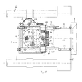
- Fig. 1 einen Kurbeltrieb für einen Auswerferstift in der Draufsicht (teilweise im Schnitt),
- Fig. 2 den Kurbeltrieb gemäß Fig. 1 von hinten gesehen in Richtung auf die Formaufspannplatte,
- Fig. 3 den Kurbeltrieb gemäß Figuren 1 und 2 in Seitenansicht.
- In den Figuren ist eine Vorrichtung zum Auswerfen von Spritzgußteilen aus Spritzgießformen allgemein mit dem Bezugszeichen 1 versehen. Sie besteht im wesentlichen aus einer Traverse 2, genauer einer Platte, die durch zwei Profilstege 3 und 4 mit der beweglichen Formaufspannplatte 5 einer Spritzgießmaschine verbunden ist, wobei die Formaufspannplatte 5 auf vier Holmen 6 und 7, von denen lediglich zwei dargestellt sind, verschiebbar geführt ist. Hierzu dient eine nicht dargestellte Schließeinheit. Auf der der Vorrichtung 1 entgegengesetzten Seite der Formaufspannplatte 5 ist eine Hälfte 8 eines Spritzgießwerkzeuges angeordnet. Zusammen mit dieser Werkzeughälfte 8 wird mittels der Schließeinheit die bewegliche Formaufspannplatte 5 auf eine ( ebenfalls nicht dargestellte ) feststehende Formaufspannplatte zugefahren, an der die andere Werkzeughälfte angeordnet ist.
- Auf den beiden Profilstangen 3 und 4 verschiebbar geführt ist ein die beiden Profilstangen miteinander verbindender Schlitten 9. Zur Minimierung der Reibung sind Kugelbüchsen 10 und 11 vorgesehen, die auf den Profilstangen 3 und 4 gleiten. Die Profilstangen 3 und 4 stehen lotrecht auf der Formaufspannplattenfläche und sind mittels die Aufspannplatte 5 durchsetzenden Bolzenschrauben 12 und 13 an dieser befestigt.
- Der Schlitten 9 besitzt zwischen den Kugelbüchsen 10 und 11 eine Ausnehmung 14, in der ein Bolzen 15 vorgesehen ist, der als Welle für das eine Ende eines Hebels 16 dient, dessen anderes Ende auf einem Bolzen 17 gelagert ist, der exzentrisch auf einer Kurbelscheibe 18 angeordnet ist. Die Kurbelscheibe 18 ist drehbar auf einer Welle 19 gelagert, die wiederum, wie aus Fig. 2 ersichtlich, in Lagern 20 in Wänden 21 eines die Vorrichtung aufnehmenden Gehäuses gelagert ist.
- Wie sich weiter aus Fig. 2 ergibt, sind zwei parallel zueinander angeordnete Kurbelscheiben 18 vorgesehen, die neben dem Bolzen 17 noch durch einen weiteren Bolzen 22 miteinander verbunden sind, so daß zwischen den beiden Kurbelscheiben keine Relativbewegung möglich ist. Beide Kurbelscheiben 18 sind als Zahnräder ausgebildet, deren Zähne 24 ( die lediglich angedeutet sind ) mit ( ebenfalls nur angedeuteten ) Zähnen 25 zweier Ritzel 26 kämmen, die auf einer Antriebswelle 27 angeordnet sind, die, wie aus den Figuren 2 und 3 ersichtlich, über eine Kupplung 28 mit der Abtriebswelle eines nicht im einzelnen dargestellten Getriebes verbunden ist, welches wiederum von einem elektrischen Servomotor 29 betrieben wird.
- Am deutlichsten aus Fig. 3 erkennbar ist die Vorrichtung zusätzlich zu den Bolzenschrauben 12 und 13 noch mit Hilfe des Winkelblechs 30 und des Trägers 31 fixiert, so daß zwischen der Vorrichtung 1 und der beweglichen Formaufspannplatte 5 keine Relativbewegung möglich ist, wobei der Träger 31 der Motorbefestigung dient.
- Die Ausnehmung 14 im Schlitten 9 deckt in Richtung Formaufspannplatte 5 eine auf den Schlitten 9 aufgeschraubte Platte 32 ab, die eine Aufnahme 33 für einen lediglich strichliert angedeuteten Auswerferstift 34 aufweist, der in einer die Formaufspannplatte 5 und die Formhälfte 8 durchsetzenden Bohrung verschiebbar geführt ist.
- Die Arbeitsweise der Vorrichtung ist folgende: Sobald das gespritzte Formteil in der Form ausreichend fest ist, wird die Formaufspannplatte 5 mittels der Schließeinheit von der feststehenden Formaufspannplatte entfernt. Entweder schon jetzt oder erst, wenn die Öffnungsbewegung abgeschlossen ist, wird die Auswerfervorrichtung 1 aktiviert. Der servoelektrische Antrieb bewegt dabei den Auswerferstift nach einem der Antriebseinheit einprogrammierten Schema, bei dem eine auf das jeweils zu entfernende Teil abgestimmte Auswurfparabel realisiert wird.
- Sollte es bei schwer entformbaren Teilen erforderlich sein, wird der Auswerferstift über seinen Antrieb mehrfach hin- und herbewegt.
Claims (5)
dadurch gekennzeichnet,
daß der Kurbeltrieb (16,18) in einem Gestell angeordnet ist, das im wesentlichen aus einer Traverse (2) und zwei parallel zu dem mindestens einem Auswerferstift (34) verlaufenden Profilen (3,4) besteht, welche die Traverse (2) mit der die Formhälfte (8) tragenden Formaufspannplatte (5) verbinden, wobei der Kurbeltrieb aus mindestens einer im Gestell drehbar gelagerten Kurbelscheibe (18) mit einem exzentrisch an dieser gelagerten Hebel (16) besteht, der an einem auf den Profilen (3,4) verschiebbar geführten Schlitten (9) angreift, welcher den Auswerferstift (34) trägt, und die Kurbelscheibe (18) über einen eigenen motorischen Antrieb (29) verfügt.
dadurch gekennzeichnet,
daß der motorische Antrieb ein Servomotor (29) ist.
dadurch gekennzeichnet,
daß die Kraftübertragung vom Motor (29) auf die Kurbelscheibe (18) mittels eines Getriebes und einer Kupplung (28) erfolgt.
dadurch gekennzeichnet,
daß der Kurbeltrieb (16,18) in einem Gehäuse Untergebracht ist, wobei die Kurbelscheibe (18) in den Gehäusewänden (21) gelagert ist.
dadurch gekennzeichnet,
daß der Kurbeltrieb aus zwei parallel zueinander angeordneten Kurbelscheiben (18) besteht, die synchron antreibbar sind und zwischen denen der den Schlitten (9) verschiebende Hebel (16) gelagert ist.
Applications Claiming Priority (4)
| Application Number | Priority Date | Filing Date | Title |
|---|---|---|---|
| DE4340946 | 1993-12-01 | ||
| DE4340946 | 1993-12-01 | ||
| DE4402291A DE4402291C1 (de) | 1993-12-01 | 1994-01-27 | Vorrichtung zum Auswerfen von Spritzgußteilen |
| DE4402291 | 1994-01-27 |
Publications (2)
| Publication Number | Publication Date |
|---|---|
| EP0657271A1 true EP0657271A1 (de) | 1995-06-14 |
| EP0657271B1 EP0657271B1 (de) | 1998-06-03 |
Family
ID=25931685
Family Applications (1)
| Application Number | Title | Priority Date | Filing Date |
|---|---|---|---|
| EP94115416A Expired - Lifetime EP0657271B1 (de) | 1993-12-01 | 1994-09-30 | Vorrichtung zum Auswerfen von Spritzgussteilen |
Country Status (2)
| Country | Link |
|---|---|
| EP (1) | EP0657271B1 (de) |
| AT (1) | ATE166828T1 (de) |
Cited By (5)
| Publication number | Priority date | Publication date | Assignee | Title |
|---|---|---|---|---|
| WO1997047459A1 (de) * | 1996-06-11 | 1997-12-18 | Otto Hofstetter Ag Werkzeug- Und Formenbau | Ausstosservorrichtung |
| WO2002040246A1 (de) * | 2000-11-14 | 2002-05-23 | Netstal-Maschinen Ag | Verfahren und vorrichtung zum ausstossen von spritzgiessteilen |
| CN102285078A (zh) * | 2011-08-24 | 2011-12-21 | 佘晓峰 | 全电式双缸联动注射单元 |
| EP2719517A1 (de) * | 2012-10-12 | 2014-04-16 | Wittmann Battenfeld GmbH | Spritzgießmaschine |
| CN115008752A (zh) * | 2022-05-23 | 2022-09-06 | 深圳锐沣科技有限公司 | 顶起机构和三维打印机 |
Families Citing this family (1)
| Publication number | Priority date | Publication date | Assignee | Title |
|---|---|---|---|---|
| WO2000066341A1 (en) * | 1999-05-03 | 2000-11-09 | Milacron Inc. | Electrically driven apparatus for ejecting injection molded parts |
Citations (3)
| Publication number | Priority date | Publication date | Assignee | Title |
|---|---|---|---|---|
| JPS63107533A (ja) * | 1986-10-24 | 1988-05-12 | Fanuc Ltd | 射出成形機の製品突き出し装置 |
| JPH04168018A (ja) * | 1990-11-01 | 1992-06-16 | Fanuc Ltd | エジェクト装置 |
| DE4218822A1 (de) * | 1992-06-09 | 1993-12-16 | Kloeckner Ferromatik Desma | Vorrichtung zum Auswerfen von Spritzgußteilen aus Spritzgußformen |
-
1994
- 1994-09-30 EP EP94115416A patent/EP0657271B1/de not_active Expired - Lifetime
- 1994-09-30 AT AT94115416T patent/ATE166828T1/de not_active IP Right Cessation
Patent Citations (3)
| Publication number | Priority date | Publication date | Assignee | Title |
|---|---|---|---|---|
| JPS63107533A (ja) * | 1986-10-24 | 1988-05-12 | Fanuc Ltd | 射出成形機の製品突き出し装置 |
| JPH04168018A (ja) * | 1990-11-01 | 1992-06-16 | Fanuc Ltd | エジェクト装置 |
| DE4218822A1 (de) * | 1992-06-09 | 1993-12-16 | Kloeckner Ferromatik Desma | Vorrichtung zum Auswerfen von Spritzgußteilen aus Spritzgußformen |
Non-Patent Citations (3)
| Title |
|---|
| PATENT ABSTRACTS OF JAPAN vol. 12, no. 347 (M - 743)<3194> 19 September 1988 (1988-09-19) * |
| PATENT ABSTRACTS OF JAPAN vol. 16, no. 471 (M - 1318) 30 September 1992 (1992-09-30) * |
| THOMA: "Elektrische Spritzgiessmaschine- sparsam und genau; Kurbelschieber treibt Auswerfer an", KUNSTSTOFFE, vol. 82, no. 10, October 1992 (1992-10-01), MUNCHEN DE, pages 891 - 893, XP002045072 * |
Cited By (5)
| Publication number | Priority date | Publication date | Assignee | Title |
|---|---|---|---|---|
| WO1997047459A1 (de) * | 1996-06-11 | 1997-12-18 | Otto Hofstetter Ag Werkzeug- Und Formenbau | Ausstosservorrichtung |
| WO2002040246A1 (de) * | 2000-11-14 | 2002-05-23 | Netstal-Maschinen Ag | Verfahren und vorrichtung zum ausstossen von spritzgiessteilen |
| CN102285078A (zh) * | 2011-08-24 | 2011-12-21 | 佘晓峰 | 全电式双缸联动注射单元 |
| EP2719517A1 (de) * | 2012-10-12 | 2014-04-16 | Wittmann Battenfeld GmbH | Spritzgießmaschine |
| CN115008752A (zh) * | 2022-05-23 | 2022-09-06 | 深圳锐沣科技有限公司 | 顶起机构和三维打印机 |
Also Published As
| Publication number | Publication date |
|---|---|
| EP0657271B1 (de) | 1998-06-03 |
| ATE166828T1 (de) | 1998-06-15 |
Similar Documents
| Publication | Publication Date | Title |
|---|---|---|
| EP1673208B1 (de) | Horizontal-spritzgiessmaschine mit dreheinrichtung | |
| DE4329072C2 (de) | Durch einen Motor angetriebene Formschließ- und Zuhaltevorrichtungen an einer Spritzgießmaschine | |
| DE60004241T2 (de) | Elektrisch angetriebene vorrichtung zum auswerfen von spritzgegossenen artikeln | |
| DE3720214A1 (de) | Spritzgiessmaschine | |
| DE102011112801B4 (de) | Spritzgussmaschine mit Flachbauetagenwerkzeugträger | |
| EP3655225B1 (de) | Formschliesseinheit für eine spritzgiessmaschine | |
| DE19932741C2 (de) | Verfahren und Vorrichtung zum Schließen und Öffnen des Werkzeugs einer Kunststoffverarbeitungsmaschine | |
| DE4329070C2 (de) | Durch einen Motor angetriebene Vorrichtung zum Schließen und Zuhalten der Form einer Spritzgießmaschine | |
| EP0657271B1 (de) | Vorrichtung zum Auswerfen von Spritzgussteilen | |
| EP0567843B1 (de) | Formschliesseinheit für eine Kunststoff Spritzgiessmaschine | |
| DE68917949T2 (de) | Form mit einem einteiligen Kern zum Formen von elektrischen Batteriekästen und mit dieser Form hergestellte Kästen. | |
| DE69028634T2 (de) | Formschliesssystem | |
| EP0853537B1 (de) | Formschliesseinheit mit einer einrichtung zur entfernung von spritzteilen | |
| EP0585671B1 (de) | Auswerfereinheit für Spritzgiessmaschinen | |
| EP0597868B1 (de) | Vorrichtung zum einlegen und/oder entnehmen von gegenständen in/oder aus einer maschine | |
| DE4402291C1 (de) | Vorrichtung zum Auswerfen von Spritzgußteilen | |
| DE19535081C2 (de) | Zwei-Platten-Spritzgießmaschine | |
| DE3715161A1 (de) | Schliesseinheit fuer eine einrichtung zum spritzgiessen | |
| DE4328844C2 (de) | Spritzgießmaschine, insbesondere Kunststoffspritzgießmaschine | |
| EP1441893B1 (de) | Vorrichtung zum entnehmen und/oder einlegen von werkstücken in ein spritzgiesswerkzeug einer spritzgiessmaschine | |
| EP1277557A1 (de) | Spritzgiessmaschine | |
| EP1480806B1 (de) | Auswerfereinheit mit ovalradgetriebe | |
| DE4213654C2 (de) | Gießform für eine Kunststoff-Spritzgießmaschine und Verfahren zur Herstellung von Spritzteilen in einer Gießform | |
| DE4417281C2 (de) | Gehäuse für Kraftfahrzeugverstelleinrichtungen und Vorrichtung zur Herstellung dieses Gehäuses | |
| DE10308303B4 (de) | Spritzgießeinrichtung mit einer Verriegelungseinrichtung |
Legal Events
| Date | Code | Title | Description |
|---|---|---|---|
| PUAI | Public reference made under article 153(3) epc to a published international application that has entered the european phase |
Free format text: ORIGINAL CODE: 0009012 |
|
| AK | Designated contracting states |
Kind code of ref document: A1 Designated state(s): AT CH DE FR IT LI LU NL |
|
| 17P | Request for examination filed |
Effective date: 19950620 |
|
| 17Q | First examination report despatched |
Effective date: 19961230 |
|
| GRAG | Despatch of communication of intention to grant |
Free format text: ORIGINAL CODE: EPIDOS AGRA |
|
| GRAG | Despatch of communication of intention to grant |
Free format text: ORIGINAL CODE: EPIDOS AGRA |
|
| GRAH | Despatch of communication of intention to grant a patent |
Free format text: ORIGINAL CODE: EPIDOS IGRA |
|
| GRAH | Despatch of communication of intention to grant a patent |
Free format text: ORIGINAL CODE: EPIDOS IGRA |
|
| GRAA | (expected) grant |
Free format text: ORIGINAL CODE: 0009210 |
|
| AK | Designated contracting states |
Kind code of ref document: B1 Designated state(s): AT CH DE FR IT LI LU NL |
|
| REF | Corresponds to: |
Ref document number: 166828 Country of ref document: AT Date of ref document: 19980615 Kind code of ref document: T |
|
| REG | Reference to a national code |
Ref country code: CH Ref legal event code: EP |
|
| ITF | It: translation for a ep patent filed | ||
| REF | Corresponds to: |
Ref document number: 59406128 Country of ref document: DE Date of ref document: 19980709 |
|
| PGFP | Annual fee paid to national office [announced via postgrant information from national office to epo] |
Ref country code: FR Payment date: 19980710 Year of fee payment: 5 |
|
| REG | Reference to a national code |
Ref country code: CH Ref legal event code: NV Representative=s name: HUG INTERLIZENZ AG |
|
| PGFP | Annual fee paid to national office [announced via postgrant information from national office to epo] |
Ref country code: CH Payment date: 19980924 Year of fee payment: 5 |
|
| PG25 | Lapsed in a contracting state [announced via postgrant information from national office to epo] |
Ref country code: LU Free format text: LAPSE BECAUSE OF NON-PAYMENT OF DUE FEES Effective date: 19980930 |
|
| PGFP | Annual fee paid to national office [announced via postgrant information from national office to epo] |
Ref country code: NL Payment date: 19980930 Year of fee payment: 5 |
|
| ET | Fr: translation filed | ||
| PLBE | No opposition filed within time limit |
Free format text: ORIGINAL CODE: 0009261 |
|
| STAA | Information on the status of an ep patent application or granted ep patent |
Free format text: STATUS: NO OPPOSITION FILED WITHIN TIME LIMIT |
|
| 26N | No opposition filed | ||
| PGFP | Annual fee paid to national office [announced via postgrant information from national office to epo] |
Ref country code: AT Payment date: 19990921 Year of fee payment: 6 |
|
| PG25 | Lapsed in a contracting state [announced via postgrant information from national office to epo] |
Ref country code: LI Free format text: LAPSE BECAUSE OF NON-PAYMENT OF DUE FEES Effective date: 19990930 Ref country code: CH Free format text: LAPSE BECAUSE OF NON-PAYMENT OF DUE FEES Effective date: 19990930 |
|
| PG25 | Lapsed in a contracting state [announced via postgrant information from national office to epo] |
Ref country code: NL Free format text: LAPSE BECAUSE OF NON-PAYMENT OF DUE FEES Effective date: 20000401 |
|
| REG | Reference to a national code |
Ref country code: CH Ref legal event code: PL |
|
| PG25 | Lapsed in a contracting state [announced via postgrant information from national office to epo] |
Ref country code: FR Free format text: LAPSE BECAUSE OF NON-PAYMENT OF DUE FEES Effective date: 20000531 |
|
| NLV4 | Nl: lapsed or anulled due to non-payment of the annual fee |
Effective date: 20000401 |
|
| REG | Reference to a national code |
Ref country code: FR Ref legal event code: ST |
|
| PGFP | Annual fee paid to national office [announced via postgrant information from national office to epo] |
Ref country code: DE Payment date: 20000825 Year of fee payment: 7 |
|
| PG25 | Lapsed in a contracting state [announced via postgrant information from national office to epo] |
Ref country code: AT Free format text: LAPSE BECAUSE OF NON-PAYMENT OF DUE FEES Effective date: 20000930 |
|
| PG25 | Lapsed in a contracting state [announced via postgrant information from national office to epo] |
Ref country code: DE Free format text: LAPSE BECAUSE OF NON-PAYMENT OF DUE FEES Effective date: 20020501 |
|
| PG25 | Lapsed in a contracting state [announced via postgrant information from national office to epo] |
Ref country code: IT Free format text: LAPSE BECAUSE OF NON-PAYMENT OF DUE FEES;WARNING: LAPSES OF ITALIAN PATENTS WITH EFFECTIVE DATE BEFORE 2007 MAY HAVE OCCURRED AT ANY TIME BEFORE 2007. THE CORRECT EFFECTIVE DATE MAY BE DIFFERENT FROM THE ONE RECORDED. Effective date: 20050930 |