EP0657275A1 - Cylindre ondulé pour la fabrication de carton ondulé - Google Patents
Cylindre ondulé pour la fabrication de carton ondulé Download PDFInfo
- Publication number
- EP0657275A1 EP0657275A1 EP94118384A EP94118384A EP0657275A1 EP 0657275 A1 EP0657275 A1 EP 0657275A1 EP 94118384 A EP94118384 A EP 94118384A EP 94118384 A EP94118384 A EP 94118384A EP 0657275 A1 EP0657275 A1 EP 0657275A1
- Authority
- EP
- European Patent Office
- Prior art keywords
- roller
- corrugated
- channels
- bores
- air discharge
- Prior art date
- Legal status (The legal status is an assumption and is not a legal conclusion. Google has not performed a legal analysis and makes no representation as to the accuracy of the status listed.)
- Granted
Links
- 238000004519 manufacturing process Methods 0.000 title claims abstract description 6
- 238000010438 heat treatment Methods 0.000 claims abstract description 37
- 230000002093 peripheral effect Effects 0.000 claims description 14
- 239000003292 glue Substances 0.000 claims description 8
- 238000007789 sealing Methods 0.000 claims description 4
- 230000006835 compression Effects 0.000 claims description 2
- 238000007906 compression Methods 0.000 claims description 2
- 230000000284 resting effect Effects 0.000 claims description 2
- 238000000926 separation method Methods 0.000 claims 1
- 229920006395 saturated elastomer Polymers 0.000 description 5
- 238000004026 adhesive bonding Methods 0.000 description 2
- 238000010276 construction Methods 0.000 description 2
- 230000000694 effects Effects 0.000 description 2
- 239000000356 contaminant Substances 0.000 description 1
- 230000002349 favourable effect Effects 0.000 description 1
- 230000010354 integration Effects 0.000 description 1
- 230000003068 static effect Effects 0.000 description 1
Images




Classifications
-
- B—PERFORMING OPERATIONS; TRANSPORTING
- B31—MAKING ARTICLES OF PAPER, CARDBOARD OR MATERIAL WORKED IN A MANNER ANALOGOUS TO PAPER; WORKING PAPER, CARDBOARD OR MATERIAL WORKED IN A MANNER ANALOGOUS TO PAPER
- B31F—MECHANICAL WORKING OR DEFORMATION OF PAPER, CARDBOARD OR MATERIAL WORKED IN A MANNER ANALOGOUS TO PAPER
- B31F1/00—Mechanical deformation without removing material, e.g. in combination with laminating
- B31F1/20—Corrugating; Corrugating combined with laminating to other layers
- B31F1/24—Making webs in which the channel of each corrugation is transverse to the web feed
- B31F1/26—Making webs in which the channel of each corrugation is transverse to the web feed by interengaging toothed cylinders cylinder constructions
- B31F1/28—Making webs in which the channel of each corrugation is transverse to the web feed by interengaging toothed cylinders cylinder constructions combined with uniting the corrugated webs to flat webs ; Making double-faced corrugated cardboard
- B31F1/2845—Details, e.g. provisions for drying, moistening, pressing
- B31F1/285—Heating or drying equipment
Definitions
- the invention relates to a corrugated roller for the production of corrugated cardboard with the features specified in the preamble of claim 1.
- Such a corrugating roller such as e.g. is known from EP-A-0 025 759, is used in corrugated cardboard machines in particular for the production of single-sided corrugated cardboard.
- the central corrugating roller it is generally in contact with a second corrugating roller, the so-called corrugated web of corrugated cardboard being passed through the nip between the two corrugating rollers and then glued by means of a glue application roller which is in contact with the corrugating roller.
- the so-called cover sheet is connected to the glued corrugated sheet by means of a pressure roller, which is also in contact with the corrugated roller, in order to complete the one-sided corrugated cardboard.
- the central corrugating roller should fulfill further functions, which in particular support effective corrugation and a clean application of glue.
- the corrugated roller should be heatable in order to simplify the corrugation by heating the corrugated sheet.
- the corrugated sheet must be held on the corrugated surface of the corrugated roller in the looping area of the corrugated sheet from the first nip between the central corrugated roller and the second corrugated roller to the second nip between the central corrugated roller and the pressure roller, so that the corrugated sheet lies cleanly in the recesses of the corrugation. Only then is a clean gluing of the corrugated sheet guaranteed only at the elevations of the corrugation and perfect corrugation of the corrugated sheet.
- EP-A-0 025 759 to provide a pneumatic fixing device in the form of a suction device for the section of the corrugated web that wraps around the corrugated roll, which suction device has suction bores in the roll shell that run parallel to the axis of rotation of the corrugated roll are connected via openings to the corrugated surface of the roll shell and, on the other hand, to a vacuum source.
- a heating medium is provided in the central cavity of the roller - e.g. Steam under high pressure - to initiate.
- the heating device designed in this way is disadvantageous from various aspects.
- the entire roll shell which is thick-walled for reasons of high rigidity of the corrugated rolls, must first be heated from the inside out until its shell surface shows the desired temperature. This is very energy intensive.
- the generally existing roller flanges which close the roller shell at both ends, are fully subjected to the high pressure of the steam, so that the additional pressure forces due to the saturated steam must be included in the dimensioning of the flanges and their fastening elements. This leads to an oversizing of the corresponding corrugated roller components which is not necessary per se.
- This construction of the suction device is disadvantageous in that the bores in the roll shell are relatively long and very thin. In order to a high pressure loss occurs on the suction path from the outer surface of the corrugated roller to the interior of the roller. In addition, the hollow interior of the roll shell is relatively large. In order to compensate for the pressure loss mentioned and because of the large volume of the suction space, a suction pump which is powerful and therefore larger and more complex is required for the suction device. To make matters worse, "wrong" air is sucked in via the suction bores in the roller jacket, which open out into the section of the jacket surface not covered by the corrugated sheet, which contributes to a further reduction in the suction effect.
- Corrugated rollers as they correspond to the basic construction known from EP-A-0 025 759, are also known from EP-A-0 009 907, EP-A-0 034 906 and US-A-1 264 506. These corrugated rollers also have the disadvantages discussed.
- the invention has for its object to develop a corrugated roller of the generic type in such a way that, while maintaining an effective pneumatic fixing device, the heating is improved in such a way that the heating can be operated with improved efficiency and correspondingly reduced energy expenditure, and the disadvantages discussed due to the loading of the hollow roller interior additionally occurring axial forces can be avoided.
- a surprising advantage of the integration of the conveying channels in the roller shell is further that the heat conduction path between the conveying channels and the outer surface of the roller shell is not only - as discussed - much shorter than in the prior art, but also that the full cross section radially outside the conveying channels of the roll shell is available for heat conduction. This means that the heat is transported to the outer surface unhindered, which is conducive to rapid and effective heating of the outer surface.
- the heat transport through the wall of the roller shell is, on the other hand, hindered due to the air discharge channels which interrupt them.
- Claims 2 and 3 characterize advantageous refinements of the mutual assignment of the conveying and air discharge channels arranged in the roll shell. This results in a uniform loading of the section of the corrugated web that wraps around the corrugated roller on the one hand and a uniform heating of the outer surface of the roller shell on the other hand.
- the heating medium can be fed in and out at one of the two roller ends. This shortens the supply and discharge lines for the heating medium, e.g. between a steam generator and the corrugated roller.
- the heating behavior can be optimally adapted to practical conditions by an appropriate combination of supply and return lines in the same or different numbers. Further details can be found in the exemplary embodiment.
- Claim 5 characterizes a structurally simple configuration of the flow connection between the supply and return lines, which belong together in pairs or groups.
- the measures specified in claims 6 and 7 serve to improve the infeed and outfeed of the heating medium, in particular through the ring distributor groove provided on the infeed side according to claim 7 achieving a uniform infeed of the heating medium in all supply lines with a corresponding equalization of the heating effect over the circumference of the corrugated roller becomes.
- Claim 8 characterizes a particularly simple manufacturing design for the delivery channels.
- Claims 9 to 13 relate to advantageous refinements of the pneumatic fixing device in the form of a suction device, by means of which, in particular, it is avoided that "wrong" air is sucked in via the sections of the lateral surface which are not wrapped by the corrugated sheet.
- the measure specified in claim 14 avoids that the air inlet openings connected to the air discharge ducts in the roller jacket in the jacket surface e.g. become clogged with contaminants.
- the pressure system characterized in claims 15 and 16 can also be used.
- Such pressure systems are known in principle from the prior art, but so far, air inlet openings and air discharge channels cooperating with such pressure systems have not been provided in the roller jacket of the corrugated roller.
- the use of such air inlet openings and air discharge channels in the roll shell, as specified in claim 15, is advantageous in that an effective pressure gradient is built up over the corrugated cardboard web, which strongly supports the reliable fixing of the web on the corrugated roll.
- the corrugated cardboard machine 1 shown schematically in FIG. 1 is used to produce single-sided corrugated cardboard. It has a central corrugating roller 2, which is driven in rotation about its axis of rotation 3. A corrugated web 4 is guided around the corrugated roller 2 at a wrap angle W of 180 °. Arranged below the corrugating roller 2 is a counter-corrugating roller 5 which is driven in rotation in the opposite direction to the corrugating roller 2 and whose corrugation meshes with the corrugation of the corrugating roller 2. As a result, the corrugated web 4, which is smooth before the entry into the nip formed between the corrugating roller 2 and the counter-corrugating roller 5, is pressed into the corrugation of the corrugating roller 2 and thus corrugated.
- a glue unit 6 is arranged to the side of the corrugating roller 2, which has an application roller 7 and a so-called squeezing roller 8 and an open glue tub 9.
- Squeeze roller 8 and applicator roller 7, on the one hand, and applicator roller 7 and corrugating roller 2, on the other hand, are in mutual contact, as a result of which a defined layer of glue is applied to the protruding areas of corrugated web 4 in the usual way.
- a smooth pressure roller 10 is arranged above the corrugating roller 2, which in turn forms a nip with the corrugating roller 2.
- the corrugated sheet 4 and a cover sheet 11 brought up by a supply roll are passed through this, whereby these two sheets 4, 11 are combined to form the one-sided corrugated cardboard sheet 12.
- the central corrugated roller 2 has a heater (not shown in FIG. 1) and a suction device for the corrugated web 4 in order to reliably fix the latter in the area of the wrap angle W on the corrugated roller. Heating and suction device are explained in more detail below.
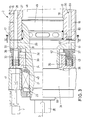
- the corrugated roller 2 has a hollow cylindrical roller jacket 13.
- the outer lateral surface 14 is provided with a corrugation 15 running parallel to the axis of rotation 3, which is only partially shown in FIG. 2.
- a plurality of annular grooves 16, which are arranged at a uniform distance from one another, are provided in the lateral surface 14 and each run in a plane perpendicular to the axis of rotation 3.
- the annular grooves 16 have a somewhat greater depth than the corrugation 15 (see FIGS. 3, 4).
- roller flanges 19, 20 are arranged, which are screwed to the roller shell 13 in a conventional manner and close the interior thereof.
- Both roller flanges 19, 20 each have a bearing journal 21, 22 projecting coaxially to the axis of rotation 3, by means of which the corrugated roller 2 is rotatably mounted in corresponding roller bearings 23 in the roller stands 24, 25 on both sides.
- One bearing journal 21 continues into a shaft journal 26, which is connected to a drive motor (not shown) for the rotational movement of the corrugated roller 2.
- the corrugated roller 2 has a suction device for the section of the corrugated web 4 surrounding the corrugated roller 2 in the area of the wrap angle W.
- This suction device comprises parallel to the axis of rotation 3 of the corrugated roller 2 over the length of the roller extending suction bores 27 in the roller shell 13, which can be acted upon with vacuum in a manner to be described.
- the suction bores 27 are each connected to the bottom of the annular grooves 16 via openings 28 which extend radially outwards.
- the suction bores 27 are each carried out from the roller jacket 13 into the roller flange 19 at one end 17 of the corrugated roller 2, in that passage bores 29 axially aligned with the suction bores 27 are made in the roller flange 19.
- These through bores 29 open out on the end face 30 of the roller flange 19.
- the annular area into which the mouth openings 31 of the through bores 29 emerge - that is to say essentially the area which coincides with the annular cross section of the roll shell 13 - is covered by a stationary ring cover 32 which lies tightly against the end face 30 of the roll flange 19 and which is provided on its rear side facing away from the end face 30 with an integrally molded ring extension 33.
- This ring shoulder 33 is in a corresponding Ring groove 34 in the roller stand 24 is mounted parallel to the axis of rotation 3.
- a plurality of helical compression springs 35 are provided which are arranged over the circumference of the ring cover 32 and are inserted between the groove base 36 of the ring groove 34 and the ring shoulder 33.
- the ring cover 32 also has, in its contact surface 37 resting on the roller flange 19, a partially ring-shaped recess 38 which extends over the wrap angle W, as is made clear in FIG. 8 by the outline of the recess 38 shown in broken lines.
- the recess 38 is connected to a connection bore 39 in the ring extension 33, which opens into the annular groove 34.
- the latter is in turn connected via a through-channel 40 to a connection box 41 on the roller stand 24, to which a suction line (not shown) to a vacuum source V can be connected.
- the ring cover 32 is secured against rotation in the annular groove 34 by a pin 42 fastened in the ring shoulder 33, which engages in a slot 43 on the roller stand 24.
- the suction bores 27 are connected to the vacuum source depending on the rotational position of the corrugating roller 2 in such a way that only the openings 28 in the corrugated lateral surface 14 are subjected to negative pressure, which are located in the circumferential section of the corrugating roller 2 wrapped by the corrugated web 4 are. This means that the suction device does not draw “wrong" air.
- FIGS. 4 and 5 The alternative embodiment of the suction device shown in more detail in FIGS. 4 and 5 serves the same purpose.
- This in turn has suction bores 27 with openings 28 to the groove base of the annular grooves 16, the suction bores 27 being closed in the region of their ends at the roller flanges 19, 20 by fastening screws 44, which at the same time provide a firm connection between the roller shell 13 and the roller flanges 19 , 20 serve.
- the suction bores 27 are each connected to a vacuum control device 46 via a connecting line 45.
- Each connecting line 45 consists of a radial branch 47 which, starting from the respective suction bore 27, the roller jacket 13 and a retaining pin 49 of the roller flange 19 which engages in the interior 48 of the roller jacket 13 radially inwards enforced.
- Each radial branch 47 of the connecting lines 45 opens into an associated axial branch 50, which is formed by a blind hole which passes through the roller flange 19 starting from the inside 51 of the holding pin 49 into the region of the outer end of the bearing pin 21.
- each axial branch 50 is closed by a screw cap 52.
- Each axial branch 50 is also provided with a radially outward opening 54 in front of its blind end 53, which opens into the peripheral surface 55 of the journal 21.
- the axial branches 50 of the connecting lines 45 are distributed in the radial and peripheral directions over the bearing journal 21.
- the vacuum control device 46 by means of which vacuum is only applied to the suction bores 27 and the corresponding openings 28, which lie in the area of the circumferential surface 14 encircled by the corrugated web 4, has a pot-like housing 56, which on the outside facing away from the corrugated roller 2 of the roller stand 24 is attached and tightly surrounds the end of the journal 21 projecting in this area.
- the interior of the housing 56 in which the openings 54 of the connecting lines 45 open, is divided radially into a negative pressure space 57 and an atmospheric pressure or positive pressure space 58.
- the semi-ring-shaped vacuum space 57 is connected to a vacuum source V via a connecting flange 59 - that is, e.g. a vacuum pump - in connection.
- the peripheral extent of the overpressure space 58 coincides with the peripheral arrangement and size of the wrapping area of the corrugated web 4 around the corrugated roller 2.
- the overpressure space 58 is narrowed by a partially annular insert 60 to an annular gap 61, a sealing body 63 for pressure-tight radial division of the housing 56 into the underpressure 57 and overpressure space 58 being fastened to each of the two ends 62 of the insert 60 pointing in the peripheral direction.
- the annular gap 61 is connected via a connecting channel 64 in the insert 60 to a connecting flange 65 which can flow freely into the atmosphere - then the annular gap 61 is subjected to atmospheric pressure - or which can be connected to an overpressure source H (for example a pump) - Then the annular gap 61 is pressurized.
- H for example a pump
- the heating device works with a heating medium, such as saturated steam at a pressure of 16 bar and a temperature of approx. 200 ° C., which steam is brought in by a corresponding steam generator and introduced into the corrugating roller 2.
- a heating medium such as saturated steam at a pressure of 16 bar and a temperature of approx. 200 ° C.
- the corrugated roller 2 has conveying bores 66 which run parallel to the axis of rotation 3 in the roller jacket 13 between the suction bores 27 and which are formed as bores running from an annular end face of the roller jacket 13 to the opposite end face. In the area of their outer ends, these delivery bores 66 are closed by screw plugs 67.
- the delivery bores 66 run between the suction bores 27 such that these two types of bores alternate in the circumferential direction U. Conveying 66 and suction bores 27 are arranged equidistantly in the roller jacket 13. Two successive delivery bores 66 in the circumferential direction U are combined in pairs to form a feed line 68 and a return line 69. The steam can thus be fed into and out of the delivery bores 66 from one side of the corrugated roller 2.
- the saturated steam supplied by a (not shown) steam generator via a pipeline 70 is fed into a steam channel 72 in the bearing journal 22 via a bushing 71 designated as a whole, which channel is designed as a blind hole arranged coaxially to the axis of rotation 3.
- the delivery bores 66 which are combined in pairs as feed line 68 or return line 69, are connected to one another.
- the connection takes place in each case via through channels 80 which run radially inwards through the roller shell 13 and which open out on the inner surface 78 of the roller shell 13.
- the orifices of the two through-channels 80 of a feed line 68 and a return line 69 are connected to one another via conveyor recesses 81, which are elongated in plan view, on the peripheral surface 82 of the holding pin 49 of the roller flange 19.
- the saturated steam fed in via the respective feed line 68 thus reaches the associated return line 69, where it is returned to the opposite end 18 of the corrugated roller 2 in the region of the roller flange 20.
- the return lines 69 are connected to return channels 83, which run radially inward through the roller jacket 13 and the holding pin 74 of the roller flange 20 and open into a central blind hole 84. The latter extends from the blind end 73 of the steam channel 72.
- a return pipe 85 is inserted sealingly, which leads centrally in the steam channel 72 through the bushing 71 to the outside and from there back to the steam generator. This results in a closed steam circuit for heating the corrugated roller 2.
- FIG. 9 A modified embodiment of the heating device for the corrugated roller 2 can be described in more detail with reference to FIG. 9. It should be noted that the position of the main section in FIG. 9 essentially corresponds to that of FIG. 8, but in the right-hand circumferential area of FIG. 9 the corrugated roller 2 is shown with a section position such as the straight line VI-VI according to FIG 3 corresponds.
- saturated steam is in turn supplied via the central steam channel 72, which reaches the ring distributor groove 76 via the six radially running flow channels 75. From there, nine feed-through channels 79 each lead to one of the nine feed lines 68. As in the exemplary embodiment according to FIG. 8, the feed channels 75, the ring distributor groove 76 and the through channels 79 are arranged in the region of the holding pin 74.
- a group of three feed lines 68 and an associated return line 69 each have through channels 80 which open together into a conveying recess 81 ′ on the peripheral surface 82 of the holding pin 49.
- three feed lines 68 are connected to each other in groups with a return line 69 with the aid of the three delivery recesses 81 ′, each of which extends over a peripheral angle of approximately 100 ° in the peripheral direction via the peripheral surface 82 of the holding pin 49 extend.
- the three return lines 69 are each assigned return channels 83, which are also indicated by dashed lines in the main section of FIG. 9 and are located behind the supply channels 75 in the axial direction. 8, in turn, flow into the return pipe 85 in the steam channel 72.
- the flow rates in the flow and return lines and thus the heat transfer from the corrugated roller to the corrugated web can be adapted to the respective application.
- FIGS. 10 and 11 show an alternative embodiment for the connection of the suction bores 27 to the corrugation 15.
- groove segments 86 are provided in the lateral surface 14, each of which extends transversely to the corrugation 15 over a partial circumferential length of the roller shell 13.
- the groove base 87 of the groove segments 86 is designed as a concave, outwardly curved partial circular arc, which in each case intersects a suction bore 27.
- Suction openings 88 are thus formed in order to create a suction connection between the suction bores 27 and the groove segments 86. This eliminates the need to drill holes 28.
- this arrangement results in a large opening area, as a result of which the connection between the suction bores 27 and the groove segments 86 is not clogged.
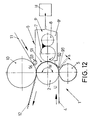
- FIG. 12 A corrugated cardboard machine with a printing system is explained in more detail below with reference to FIG. 12.
- This corrugated cardboard machine is basically constructed like that shown in FIG. 1 and in turn has a central corrugating roller 2, a counter corrugating roller 5 and a smooth pressure roller 10 and a gluing unit 6 with application roller 7 and squeezing roller 8.
- the glue pan 9 ' is designed as a pressure box which is open on one side and is connected to a positive pressure source via a connecting piece 90.
- the open side 91 is essentially pressure-tight with the area wrapped around the corrugated cardboard web 12 (wrap angle W) of the lateral surface 14 of the corrugated roller 2.
- the lower, horizontal edge 92 of the open side 91 is provided with a sealing strip 95, which closes the glue pan 9 'on its underside with a gap s against the lower corrugating roller 5.
- a sealing roller 94 which rolls over the width of the corrugated cardboard web including the cover web 11 on the jacket of the pressure roller 10.
- the corrugating roller 2 itself is e.g. like the corrugated roller explained with reference to FIGS. 3 to 9, it being possible to dispense with the connection of a vacuum source.
- the suction bores 27 then serve as air discharge ducts connected to the atmosphere, by means of which the air which is pressed under the excess pressure through the corrugated cardboard web and enters the air discharge ducts via the openings 28 and 88 is carried away.
- the heating device of the corrugated roller 2 can be adopted unchanged in the embodiment shown in FIG. 12.
Landscapes
- Engineering & Computer Science (AREA)
- Mechanical Engineering (AREA)
- Machines For Manufacturing Corrugated Board In Mechanical Paper-Making Processes (AREA)
Applications Claiming Priority (2)
| Application Number | Priority Date | Filing Date | Title |
|---|---|---|---|
| DE4341730 | 1993-12-08 | ||
| DE4341730A DE4341730A1 (de) | 1993-12-08 | 1993-12-08 | Riffelwalze für die Herstellung von Wellpappe |
Publications (3)
| Publication Number | Publication Date |
|---|---|
| EP0657275A1 true EP0657275A1 (fr) | 1995-06-14 |
| EP0657275B1 EP0657275B1 (fr) | 1998-05-20 |
| EP0657275B2 EP0657275B2 (fr) | 2000-09-13 |
Family
ID=6504405
Family Applications (1)
| Application Number | Title | Priority Date | Filing Date |
|---|---|---|---|
| EP94118384A Expired - Lifetime EP0657275B2 (fr) | 1993-12-08 | 1994-11-23 | Cylindre ondulé pour la fabrication de carton ondulé |
Country Status (2)
| Country | Link |
|---|---|
| EP (1) | EP0657275B2 (fr) |
| DE (2) | DE4341730A1 (fr) |
Cited By (5)
| Publication number | Priority date | Publication date | Assignee | Title |
|---|---|---|---|---|
| EP0829693A1 (fr) * | 1996-09-12 | 1998-03-18 | Talleres Iruna, S.A. | Perfectionnements a des rouleaux onduleurs chauffes par la vapeur |
| DE19836848A1 (de) * | 1998-08-14 | 2000-02-17 | Bhs Corr Masch & Anlagenbau | Wellpappe-Maschine zur Herstellung einseitiger Wellpappe |
| WO2004052764A1 (fr) * | 2002-12-10 | 2004-06-24 | Bachofen + Meier Ag Maschinenfabrik | Rouleau refroidisseur a vide |
| EP2465674A1 (fr) * | 2010-12-20 | 2012-06-20 | BHS Corrugated Maschinen- und Anlagenbau GmbH | Cylindre cannelé pour la fabrication de carton ondulé |
| CN103465520A (zh) * | 2008-06-25 | 2013-12-25 | 科尔赛尔Ip有限公司 | 复合瓦楞辊及构造辊的方法 |
Families Citing this family (1)
| Publication number | Priority date | Publication date | Assignee | Title |
|---|---|---|---|---|
| DE102007012160A1 (de) | 2007-03-12 | 2008-09-18 | Stipo Jelica | Vorrichtung und Verfahren zum Herstellen von Wellpappe sowie die Verwendung der gemäß dem Verfahren hergestellten Wellpappe |
Citations (5)
| Publication number | Priority date | Publication date | Assignee | Title |
|---|---|---|---|---|
| EP0025759A1 (fr) * | 1979-09-14 | 1981-03-25 | S.A. Martin | Machine pour la production de carton ondulé simple face |
| EP0314538A1 (fr) * | 1987-10-23 | 1989-05-03 | Papeteries Et Cartonneries Lacaux Freres | Cylindre cannelé pour une machine de fabrication de carton ondulé |
| US5156714A (en) * | 1990-05-24 | 1992-10-20 | United Container Machinery Group, Inc. | Heater for a corrugating machine |
| US5183525A (en) * | 1990-05-24 | 1993-02-02 | United Container Machinery Group, Inc. | Heater for a double facing corrugating machine |
| EP0559556A1 (fr) * | 1992-03-02 | 1993-09-08 | Manuel Torres Martinez | Installation pour la fabrication de carton ondulé |
Family Cites Families (1)
| Publication number | Priority date | Publication date | Assignee | Title |
|---|---|---|---|---|
| JPS5453096A (en) * | 1977-10-03 | 1979-04-26 | Isowa Industry Co | Core holder for apparatus for making oneeside corrugated cardboard |
-
1993
- 1993-12-08 DE DE4341730A patent/DE4341730A1/de not_active Withdrawn
-
1994
- 1994-11-23 DE DE59406016T patent/DE59406016D1/de not_active Expired - Fee Related
- 1994-11-23 EP EP94118384A patent/EP0657275B2/fr not_active Expired - Lifetime
Patent Citations (5)
| Publication number | Priority date | Publication date | Assignee | Title |
|---|---|---|---|---|
| EP0025759A1 (fr) * | 1979-09-14 | 1981-03-25 | S.A. Martin | Machine pour la production de carton ondulé simple face |
| EP0314538A1 (fr) * | 1987-10-23 | 1989-05-03 | Papeteries Et Cartonneries Lacaux Freres | Cylindre cannelé pour une machine de fabrication de carton ondulé |
| US5156714A (en) * | 1990-05-24 | 1992-10-20 | United Container Machinery Group, Inc. | Heater for a corrugating machine |
| US5183525A (en) * | 1990-05-24 | 1993-02-02 | United Container Machinery Group, Inc. | Heater for a double facing corrugating machine |
| EP0559556A1 (fr) * | 1992-03-02 | 1993-09-08 | Manuel Torres Martinez | Installation pour la fabrication de carton ondulé |
Cited By (8)
| Publication number | Priority date | Publication date | Assignee | Title |
|---|---|---|---|---|
| EP0829693A1 (fr) * | 1996-09-12 | 1998-03-18 | Talleres Iruna, S.A. | Perfectionnements a des rouleaux onduleurs chauffes par la vapeur |
| ES2131450A1 (es) * | 1996-09-12 | 1999-07-16 | Talleres Iruna S A | Perfeccionamientos en rodillos corrugadores calentados mediante vapor. |
| DE19836848A1 (de) * | 1998-08-14 | 2000-02-17 | Bhs Corr Masch & Anlagenbau | Wellpappe-Maschine zur Herstellung einseitiger Wellpappe |
| WO2004052764A1 (fr) * | 2002-12-10 | 2004-06-24 | Bachofen + Meier Ag Maschinenfabrik | Rouleau refroidisseur a vide |
| CN103465520A (zh) * | 2008-06-25 | 2013-12-25 | 科尔赛尔Ip有限公司 | 复合瓦楞辊及构造辊的方法 |
| CN103465520B (zh) * | 2008-06-25 | 2016-09-21 | 科尔赛尔Ip有限公司 | 复合瓦楞辊及构造辊的方法 |
| EP2465674A1 (fr) * | 2010-12-20 | 2012-06-20 | BHS Corrugated Maschinen- und Anlagenbau GmbH | Cylindre cannelé pour la fabrication de carton ondulé |
| US9073283B2 (en) | 2010-12-20 | 2015-07-07 | Bhs Corrugated Maschinen-Und Anlagenbau Gmbh | Corrugating roller for the manufacture of corrugated cardboard |
Also Published As
| Publication number | Publication date |
|---|---|
| EP0657275B1 (fr) | 1998-05-20 |
| DE4341730A1 (de) | 1995-06-14 |
| DE59406016D1 (de) | 1998-06-25 |
| EP0657275B2 (fr) | 2000-09-13 |
Similar Documents
| Publication | Publication Date | Title |
|---|---|---|
| DE1652366C3 (de) | Vorrichtung zum Beschichten von Blättern | |
| DE2421771B2 (de) | Maschine zur Herstellung einer Wellbahn | |
| EP3459724A2 (fr) | Installation de carton ondulé | |
| EP1905893A1 (fr) | Machine destinée à la fabrication d'une bande de carton ondulée contrecollée sur au moins un côté et rouleau tendeur pour une telle machine | |
| CH688893A5 (de) | Zugwalze zum Transport einer Materialbahn, insbesondere einer Papierbahn in einer Rollendruckmaschine. | |
| EP0657275B2 (fr) | Cylindre ondulé pour la fabrication de carton ondulé | |
| EP0659670A1 (fr) | Plieuse à lames engageantes pour machine rotative d'impression | |
| DD296737A5 (de) | Walze zur druck- und temperaturbehandlung von bahnfoermigem material | |
| DE2316127A1 (de) | Exzenterschneckenpumpe | |
| DE3530508A1 (de) | Vorrichtung zum auspressen von fliessfaehigen massen | |
| EP0752495A1 (fr) | Dispositif de pressage à zone prolongée | |
| DE2949876C2 (de) | Von außen gehaltener zylindrischer Breithalter für Schlauchware | |
| DD150724A1 (de) | Saugluftbeaufschlagte hohlwalze fuer druckmaschinen | |
| DE2634108C3 (de) | Räderfalzapparat | |
| DE4118039A1 (de) | Unterdruck-abzugswalze | |
| DE3217935A1 (de) | Bandschleifmaschine fuer spanplatten u.dgl. | |
| DE19747555A1 (de) | Heiz- und/oder kühlbarer Zylinder | |
| DE9205154U1 (de) | Saugwalze | |
| DE1286824B (de) | Durchbiegungsfreie Walze fuer Kalander, Walzwerke od. dgl. | |
| DE4324337C2 (de) | Wiederbefeuchtungseinrichtung für eine bedruckte Papierbahn | |
| EP0922921B1 (fr) | Cylindre chauffé à la vapeur, en particulier pour machines à carton ondulé | |
| DE10063025B4 (de) | Feststehende Papierleiteinrichtung | |
| EP2912959A1 (fr) | Dispositif et procédé de fabrication d'une tige de l'industrie de traitement du tabac | |
| DE1965308U (de) | Elektrisch beheizte, insbesondere induktiv beheizte galette. | |
| DE2323792A1 (de) | Vorrichtung zum trocknen von farben, lacken und klebern auf pappe, papier, kunststoff oder blech, insbesondere zum einbau in offsetmaschinen |
Legal Events
| Date | Code | Title | Description |
|---|---|---|---|
| PUAI | Public reference made under article 153(3) epc to a published international application that has entered the european phase |
Free format text: ORIGINAL CODE: 0009012 |
|
| AK | Designated contracting states |
Kind code of ref document: A1 Designated state(s): DE FR GB IT |
|
| 17P | Request for examination filed |
Effective date: 19950830 |
|
| 17Q | First examination report despatched |
Effective date: 19961111 |
|
| GRAG | Despatch of communication of intention to grant |
Free format text: ORIGINAL CODE: EPIDOS AGRA |
|
| GRAG | Despatch of communication of intention to grant |
Free format text: ORIGINAL CODE: EPIDOS AGRA |
|
| GRAH | Despatch of communication of intention to grant a patent |
Free format text: ORIGINAL CODE: EPIDOS IGRA |
|
| GRAH | Despatch of communication of intention to grant a patent |
Free format text: ORIGINAL CODE: EPIDOS IGRA |
|
| GRAA | (expected) grant |
Free format text: ORIGINAL CODE: 0009210 |
|
| AK | Designated contracting states |
Kind code of ref document: B1 Designated state(s): DE FR GB IT |
|
| GBT | Gb: translation of ep patent filed (gb section 77(6)(a)/1977) |
Effective date: 19980520 |
|
| REF | Corresponds to: |
Ref document number: 59406016 Country of ref document: DE Date of ref document: 19980625 |
|
| ITF | It: translation for a ep patent filed | ||
| ET | Fr: translation filed | ||
| PLBQ | Unpublished change to opponent data |
Free format text: ORIGINAL CODE: EPIDOS OPPO |
|
| PLBI | Opposition filed |
Free format text: ORIGINAL CODE: 0009260 |
|
| PLBF | Reply of patent proprietor to notice(s) of opposition |
Free format text: ORIGINAL CODE: EPIDOS OBSO |
|
| 26 | Opposition filed |
Opponent name: KABUSHIKI KAISHA ISOWA Effective date: 19990202 |
|
| PLBF | Reply of patent proprietor to notice(s) of opposition |
Free format text: ORIGINAL CODE: EPIDOS OBSO |
|
| PLAW | Interlocutory decision in opposition |
Free format text: ORIGINAL CODE: EPIDOS IDOP |
|
| PLAW | Interlocutory decision in opposition |
Free format text: ORIGINAL CODE: EPIDOS IDOP |
|
| PUAH | Patent maintained in amended form |
Free format text: ORIGINAL CODE: 0009272 |
|
| STAA | Information on the status of an ep patent application or granted ep patent |
Free format text: STATUS: PATENT MAINTAINED AS AMENDED |
|
| 27A | Patent maintained in amended form |
Effective date: 20000913 |
|
| AK | Designated contracting states |
Kind code of ref document: B2 Designated state(s): DE FR GB IT |
|
| GBTA | Gb: translation of amended ep patent filed (gb section 77(6)(b)/1977) | ||
| ITF | It: translation for a ep patent filed | ||
| ET3 | Fr: translation filed ** decision concerning opposition | ||
| REG | Reference to a national code |
Ref country code: GB Ref legal event code: IF02 |
|
| PGFP | Annual fee paid to national office [announced via postgrant information from national office to epo] |
Ref country code: IT Payment date: 20081126 Year of fee payment: 15 |
|
| PGFP | Annual fee paid to national office [announced via postgrant information from national office to epo] |
Ref country code: FR Payment date: 20081118 Year of fee payment: 15 |
|
| PGFP | Annual fee paid to national office [announced via postgrant information from national office to epo] |
Ref country code: DE Payment date: 20081229 Year of fee payment: 15 |
|
| PGFP | Annual fee paid to national office [announced via postgrant information from national office to epo] |
Ref country code: GB Payment date: 20081121 Year of fee payment: 15 |
|
| GBPC | Gb: european patent ceased through non-payment of renewal fee |
Effective date: 20091123 |
|
| REG | Reference to a national code |
Ref country code: FR Ref legal event code: ST Effective date: 20100730 |
|
| PG25 | Lapsed in a contracting state [announced via postgrant information from national office to epo] |
Ref country code: FR Free format text: LAPSE BECAUSE OF NON-PAYMENT OF DUE FEES Effective date: 20091130 |
|
| PG25 | Lapsed in a contracting state [announced via postgrant information from national office to epo] |
Ref country code: DE Free format text: LAPSE BECAUSE OF NON-PAYMENT OF DUE FEES Effective date: 20100601 |
|
| PG25 | Lapsed in a contracting state [announced via postgrant information from national office to epo] |
Ref country code: GB Free format text: LAPSE BECAUSE OF NON-PAYMENT OF DUE FEES Effective date: 20091123 |
|
| PG25 | Lapsed in a contracting state [announced via postgrant information from national office to epo] |
Ref country code: IT Free format text: LAPSE BECAUSE OF NON-PAYMENT OF DUE FEES Effective date: 20091123 |