EP0657285B1 - Système de distribution de clichés pour machines d'impression - Google Patents
Système de distribution de clichés pour machines d'impression Download PDFInfo
- Publication number
- EP0657285B1 EP0657285B1 EP94118918A EP94118918A EP0657285B1 EP 0657285 B1 EP0657285 B1 EP 0657285B1 EP 94118918 A EP94118918 A EP 94118918A EP 94118918 A EP94118918 A EP 94118918A EP 0657285 B1 EP0657285 B1 EP 0657285B1
- Authority
- EP
- European Patent Office
- Prior art keywords
- printing plate
- printing
- sheet
- transfer
- flexible
- Prior art date
- Legal status (The legal status is an assumption and is not a legal conclusion. Google has not performed a legal analysis and makes no representation as to the accuracy of the status listed.)
- Expired - Lifetime
Links
- 238000000605 extraction Methods 0.000 claims description 3
- 238000010586 diagram Methods 0.000 description 3
- 238000003780 insertion Methods 0.000 description 2
- 230000037431 insertion Effects 0.000 description 2
- 241001136792 Alle Species 0.000 description 1
- 238000000034 method Methods 0.000 description 1
Images

Classifications
-
- B—PERFORMING OPERATIONS; TRANSPORTING
- B41—PRINTING; LINING MACHINES; TYPEWRITERS; STAMPS
- B41F—PRINTING MACHINES OR PRESSES
- B41F27/00—Devices for attaching printing elements or formes to supports
- B41F27/12—Devices for attaching printing elements or formes to supports for attaching flexible printing formes
- B41F27/1206—Feeding to or removing from the forme cylinder
-
- B—PERFORMING OPERATIONS; TRANSPORTING
- B41—PRINTING; LINING MACHINES; TYPEWRITERS; STAMPS
- B41P—INDEXING SCHEME RELATING TO PRINTING, LINING MACHINES, TYPEWRITERS, AND TO STAMPS
- B41P2227/00—Mounting or handling printing plates; Forming printing surfaces in situ
- B41P2227/60—Devices for transferring printing plates
- B41P2227/61—Devices for transferring printing plates using the sheet feed system
Definitions
- the invention relates to a printing plate conveyor logistics for printing plates conveyed on the sheet path in printing machines.
- a method and a device for the automatic insertion and / or extraction of flexible printing plates onto / from a printing plate cylinder provided with plate grippers via sheet conveyors provided on the printing press and an intermediate cylinder provided with auxiliary grippers, which forms a transfer path together with the printing plate cylinder, is known ( DE 42 20 011).
- Conveying logistics for printing plates fed to the printing form cylinder by means of cassettes are also known (EP 435 413 A2). This conveyor logistics cannot be used for printing plates fed to the printing form cylinder via the sheet path.
- Fig. 1 the machine diagram of a sheet-fed printing machine is shown, which consists of a feed device, four identically constructed printing units DW 1; DW 2; DW 3; DW n and a discharge device 12 exists.
- the sheet conveying means are designed as sheet guide cylinders or as chain guides, not shown.
- Sheet guiding cylinders are the cylinders which convey the sheet 18 in normal operation and the printing plate 4 in printing plate conveying operation with the aid of existing gripper systems 5, such as the transfer drum 13, the printing cylinder 14 and, in the case of perfecting and printing machines, the SW drum (not shown).
- An auxiliary gripper system 7 for printing plate transport is arranged in the intermediate cylinder duct 15 of the intermediate cylinder 6.
- a rubber blanket is stretched on the intermediate cylinder 6 with generally known tensioning means.
- the intermediate cylinder 6 corresponds to the printing form cylinder 8, which is designed as a plate cylinder.
- a printing plate gripper system 9 is arranged in the printing plate cylinder channel 17 for the printing plate front edge and the printing plate rear edge, by which the printing plate 4 fed to the printing plate cylinder 8 is held and tensioned.
- the printing plate conveyor line is divided into two parts, the sheet path 16 and a number of transfer lines 19.
- the arc path is the path on which both the printing plates 4 and the sheets 18 are conveyed.
- the sheet path 16 begins with the feeder 1 and runs over the feed table 3, the pre-gripper 10, the feed drum 11 and the number of printing units DW 1; DW 2; DW 3; DW n corresponding number of printing cylinders 14 and transfer drums 13 to the discharge device 12.
- the transfer point of the printing plate from the gripper system 5 of the printing cylinder 14 to the auxiliary gripper system 7 of the intermediate cylinder 6 is referred to as the printing plate switch arc path / transfer path and is provided with the reference number 20.
- the transfer paths 19 are used to designate the distances on which the printing plates 4 are conveyed.
- Each printing unit DW 1; DW 2; DW 3; A transfer path 19 is assigned to DW n .
- the transfer path begins at the printing plate switch sheet path / transfer path 20 and leads via the intermediate cylinder 6 to the printing form cylinder 8.
- the printing plates 4 to be fed are separated by the feeder 1 and via the feed table 3, the pre-gripper 10, the feed drum 11 and the number of printing units DW 1; DW 2; DW 3; DW n corresponding number of printing cylinders 14 and transfer drums 13 (sheet path) and one intermediate cylinder 6 each fed to the printing form cylinder 8 (transfer path).
- the printing plates 4 to be executed are transferred from the respective printing form cylinder 8 via the intermediate cylinder 6 (transfer path) and one of the number of printing units DW 1; DW 2; DW 3; DW n corresponding number of printing cylinders 14 and transfer drums 13 of the discharge device 12 (sheet path) fed.
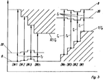
- the conveyor logistics for the printing plates are constructed on cycle lengths, the measure of the cycle length preferably being one revolution of a single-speed shaft.
- the single-turn shaft for example the printing form cylinder 8, makes one revolution in one work cycle - printing an arc 18.
- Fig. 2 the cycle length assignment to the printing press is shown schematically.
- the cycle length of the transfer path 19, which is the same for each printing unit, is designated T T in accordance with FIG.
- T E denotes the placement of the printing plates to be executed on the stack of the execution device 12.
Landscapes
- Feeding Of Articles By Means Other Than Belts Or Rollers (AREA)
Claims (7)
- Logistique de transport de plaques imprimantes pour l'introduction et/ou la sortie de plaques imprimantes flexibles (4) sur/d'un cylindre porte-forme imprimante (8) doté d'au moins un système de pinces de plaque imprimante (9) d'une machine à imprimer constituée d'au moins deux unités d'impression (DW 1; DWn), passant par le parcours de feuilles (16) et les trajets de transfert (19), au moyen de transporteurs de feuilles présents sur la machine à imprimer et comprenant des cylindres guide-feuilles (13 ; 14) dotés de systèmes de pinces (5) ainsi qu'au moyen d'un cylindre intermédiaire (6) doté d'un système de pinces auxiliaires (7) ; cette logistique est caractérisée par le fait que les plaques imprimantes (4) devant être sorties ou amenées sont transportées presque simultanément sur tous les trajets de transfert (19) comme par le fait que la fin de l'introduction des plaques imprimantes flexibles (4) et le dépôt de la dernière plaque imprimante devant être sortie s'effectue presque en même temps.
- Logistique de transport de plaques imprimantes conforme à la spécification 1, caractérisée par le fait que la plaque imprimante devant être amenée (4) à la dernière unité d'impression (DWn) démarre, sur le parcours de feuilles (16), avant les plaques imprimantes (4) destinées aux autres unités d'impression (DW 3 ; DW 2 ; DW 1).
- Logistique de transport de plaques imprimantes conforme aux spécifications 1 et 2, caractérisée par le fait que les plaques imprimantes (4) démarrant après la première plaque imprimante démarrent entre les unités d'impression, dans l'espace des aiguillages de plaques imprimantes parcours de feuilles/trajet de transfert (20) et atteignent les aiguillages de plaques imprimantes parcours de feuilles/trajet de transfert (20) pratiquement en même temps et dans l'espace d'un cycle.
- Logistique de transport de plaques imprimantes conforme à la spécification 2, caractérisée par le fait que la durée de cycle correspond à une rotation d'un arbre à un tour.
- Logistique de transport de plaques imprimantes conforme à la spécification 1, caractérisée par le fait que les plaques imprimantes (4) traversent les trajets de transfert (19) à la vitesse de transfert VT et le parcours de feuilles (16) à la vitesse de feuilles VB.
- Logistique de transport de plaques imprimantes conforme à la spécification 1, caractérisée par le fait que le moment de départ le plus tôt TStart N de la première plaque imprimante devant être amenée (4) est déterminé selon la relation suivante :

- Logistique de transport de plaques imprimantes conforme à la spécification 1, caractérisée par le fait que le moment de départ le plus tardif TStart de la première plaque imprimante devant être amenée est déterminé selon la relation suivante :

Applications Claiming Priority (2)
| Application Number | Priority Date | Filing Date | Title |
|---|---|---|---|
| DE4341359 | 1993-12-04 | ||
| DE4341359A DE4341359A1 (de) | 1993-12-04 | 1993-12-04 | Druckplattenförderlogistik für Druckmaschinen |
Publications (2)
| Publication Number | Publication Date |
|---|---|
| EP0657285A1 EP0657285A1 (fr) | 1995-06-14 |
| EP0657285B1 true EP0657285B1 (fr) | 1997-09-10 |
Family
ID=6504177
Family Applications (1)
| Application Number | Title | Priority Date | Filing Date |
|---|---|---|---|
| EP94118918A Expired - Lifetime EP0657285B1 (fr) | 1993-12-04 | 1994-12-01 | Système de distribution de clichés pour machines d'impression |
Country Status (2)
| Country | Link |
|---|---|
| EP (1) | EP0657285B1 (fr) |
| DE (2) | DE4341359A1 (fr) |
Cited By (1)
| Publication number | Priority date | Publication date | Assignee | Title |
|---|---|---|---|---|
| US8795458B2 (en) | 2008-05-27 | 2014-08-05 | Corcel Ip Limited | Method of forming single face corrugated board |
Families Citing this family (3)
| Publication number | Priority date | Publication date | Assignee | Title |
|---|---|---|---|---|
| DE4416974C3 (de) * | 1994-05-13 | 2000-01-05 | Heidelberger Druckmasch Ag | Offsetrotations-Bogendruckmaschine mit mehreren Druckwerken in Reihenbauweise |
| DE19947230C2 (de) * | 1999-10-01 | 2001-07-26 | Koenig & Bauer Ag | Verfahren zur Positionierung von Plattenzylindern einer Offsetrotations-Bogendruckmaschine |
| DE102024106827A1 (de) | 2023-04-24 | 2024-10-24 | Heidelberger Druckmaschinen Aktiengesellschaft | Plattenlogistikanlage |
Family Cites Families (2)
| Publication number | Priority date | Publication date | Assignee | Title |
|---|---|---|---|---|
| DE3721879A1 (de) * | 1987-07-02 | 1989-01-12 | Heidelberger Druckmasch Ag | Verfahren und druckmaschine zum herstellen von mehrfarbigen abdrucken |
| DE4220011C2 (de) * | 1992-05-16 | 1995-09-07 | Kba Planeta Ag | Verfahren und Einrichtung zum automatischen Ein- und/oder Auszug von flexiblen Druckplatten |
-
1993
- 1993-12-04 DE DE4341359A patent/DE4341359A1/de not_active Withdrawn
-
1994
- 1994-12-01 DE DE59404024T patent/DE59404024D1/de not_active Expired - Fee Related
- 1994-12-01 EP EP94118918A patent/EP0657285B1/fr not_active Expired - Lifetime
Cited By (3)
| Publication number | Priority date | Publication date | Assignee | Title |
|---|---|---|---|---|
| US8795458B2 (en) | 2008-05-27 | 2014-08-05 | Corcel Ip Limited | Method of forming single face corrugated board |
| US9539790B2 (en) | 2008-05-27 | 2017-01-10 | Corcel Ip Limited | Method of forming single face corrugated board |
| US9555599B2 (en) | 2008-05-27 | 2017-01-31 | Corcel Ip Limited | Method of forming single face corrugated board |
Also Published As
| Publication number | Publication date |
|---|---|
| EP0657285A1 (fr) | 1995-06-14 |
| DE59404024D1 (de) | 1997-10-16 |
| DE4341359A1 (de) | 1995-06-08 |
Similar Documents
| Publication | Publication Date | Title |
|---|---|---|
| EP0727374B1 (fr) | Procédé de commande d'alimentation de feuille | |
| EP3416905B1 (fr) | Procédé et dispositif d'obtention d'une feuille séparée dans un dispositif d'impression | |
| EP1157834B1 (fr) | Dispositif pour transporter des feuilles | |
| DE19527266C2 (de) | Bogendruckmaschine | |
| DE10222545A1 (de) | Auslegevorrichtung an einer Bogenverarbeitungsmaschine | |
| EP0657285A1 (fr) | Système de distribution de clichés pour machines d'impression | |
| DE19901699A1 (de) | Verfahren und eine Vorrichtung zur Durchführung des Verfahrens zur Beseitigung von rhythmischen Passerfehlern in Rotationsdruckmaschinen | |
| DE102009043118A1 (de) | Druckmaschine zum Drucken auf beide Seiten von Bogen | |
| DE102008005797A1 (de) | Ausleger einer bogenverarbeitenden Maschine, insbesondere Bogendruckmaschine | |
| DE4220011C2 (de) | Verfahren und Einrichtung zum automatischen Ein- und/oder Auszug von flexiblen Druckplatten | |
| DE10222543B4 (de) | Auslegevorrichtung an einer Bogenverarbeitungsmaschine | |
| EP1070583A1 (fr) | Méthode et dispositif pour le changement de plaques. | |
| DE102007028672A1 (de) | Ausleger für eine bogenverarbeitende Maschine | |
| DE3917072A1 (de) | Vorrichtung zum fliessenden transport von bogen | |
| DE10328803B4 (de) | Vorrichtung zur unterbrechungsfreien Zufuhr von zu bearbeitenden Stücken zu einer Verarbeitungsmaschine, insbesondere Zufuhr von Bogen zu einer Druckmaschine | |
| DE2331473A1 (de) | Vorrichtung zur foerderung von bogen | |
| DE19723146C2 (de) | Bogenweiche zur Unterstützung der Bogenführung | |
| EP0657284B1 (fr) | Dispositif pour l'introduction et/ou l'extraction automatique de plaques d'impression | |
| DE19505877C2 (de) | Bogendruckmaschine | |
| DE4239895A1 (de) | Zuführeinrichtung für den automatischen Einzug von flexiblen Druckplatten | |
| DE19720740C1 (de) | Schneideinrichtung zum Trennen von Bogen in einer Druckmaschine | |
| DE102023135280B3 (de) | Verfahren zum Betreiben einer bogenverarbeitenden Maschine | |
| DE102004016673B4 (de) | Bogendruckmaschine für Schön- und Widerdruck | |
| DE102005060263B4 (de) | Bogen verarbeitende Maschine mit einer Vorrichtung zum Ausschleusen ausgewählter Bogen | |
| EP0939702B1 (fr) | Procede et dispositif de transport de feuilles |
Legal Events
| Date | Code | Title | Description |
|---|---|---|---|
| PUAI | Public reference made under article 153(3) epc to a published international application that has entered the european phase |
Free format text: ORIGINAL CODE: 0009012 |
|
| AK | Designated contracting states |
Kind code of ref document: A1 Designated state(s): DE FR GB IT |
|
| 17P | Request for examination filed |
Effective date: 19950714 |
|
| 17Q | First examination report despatched |
Effective date: 19960419 |
|
| GRAG | Despatch of communication of intention to grant |
Free format text: ORIGINAL CODE: EPIDOS AGRA |
|
| GRAH | Despatch of communication of intention to grant a patent |
Free format text: ORIGINAL CODE: EPIDOS IGRA |
|
| GRAH | Despatch of communication of intention to grant a patent |
Free format text: ORIGINAL CODE: EPIDOS IGRA |
|
| GRAA | (expected) grant |
Free format text: ORIGINAL CODE: 0009210 |
|
| AK | Designated contracting states |
Kind code of ref document: B1 Designated state(s): DE FR GB IT |
|
| PG25 | Lapsed in a contracting state [announced via postgrant information from national office to epo] |
Ref country code: IT Free format text: LAPSE BECAUSE OF FAILURE TO SUBMIT A TRANSLATION OF THE DESCRIPTION OR TO PAY THE FEE WITHIN THE PRESCRIBED TIME-LIMIT;WARNING: LAPSES OF ITALIAN PATENTS WITH EFFECTIVE DATE BEFORE 2007 MAY HAVE OCCURRED AT ANY TIME BEFORE 2007. THE CORRECT EFFECTIVE DATE MAY BE DIFFERENT FROM THE ONE RECORDED. Effective date: 19970910 |
|
| REF | Corresponds to: |
Ref document number: 59404024 Country of ref document: DE Date of ref document: 19971016 |
|
| GBT | Gb: translation of ep patent filed (gb section 77(6)(a)/1977) |
Effective date: 19971210 |
|
| ET | Fr: translation filed | ||
| PLBE | No opposition filed within time limit |
Free format text: ORIGINAL CODE: 0009261 |
|
| STAA | Information on the status of an ep patent application or granted ep patent |
Free format text: STATUS: NO OPPOSITION FILED WITHIN TIME LIMIT |
|
| 26N | No opposition filed | ||
| REG | Reference to a national code |
Ref country code: FR Ref legal event code: TP Ref country code: FR Ref legal event code: CD |
|
| REG | Reference to a national code |
Ref country code: GB Ref legal event code: IF02 |
|
| PGFP | Annual fee paid to national office [announced via postgrant information from national office to epo] |
Ref country code: GB Payment date: 20041125 Year of fee payment: 11 |
|
| PGFP | Annual fee paid to national office [announced via postgrant information from national office to epo] |
Ref country code: DE Payment date: 20041222 Year of fee payment: 11 |
|
| PGFP | Annual fee paid to national office [announced via postgrant information from national office to epo] |
Ref country code: FR Payment date: 20041230 Year of fee payment: 11 |
|
| PG25 | Lapsed in a contracting state [announced via postgrant information from national office to epo] |
Ref country code: GB Free format text: LAPSE BECAUSE OF NON-PAYMENT OF DUE FEES Effective date: 20051201 |
|
| PG25 | Lapsed in a contracting state [announced via postgrant information from national office to epo] |
Ref country code: DE Free format text: LAPSE BECAUSE OF NON-PAYMENT OF DUE FEES Effective date: 20060701 |
|
| GBPC | Gb: european patent ceased through non-payment of renewal fee |
Effective date: 20051201 |
|
| PG25 | Lapsed in a contracting state [announced via postgrant information from national office to epo] |
Ref country code: FR Free format text: LAPSE BECAUSE OF NON-PAYMENT OF DUE FEES Effective date: 20060831 |
|
| REG | Reference to a national code |
Ref country code: FR Ref legal event code: ST Effective date: 20060831 |