EP0657321A1 - Mehrfachstromversorgungssystem mit hoher Verfügbarkeit für eine Lokomotive - Google Patents
Mehrfachstromversorgungssystem mit hoher Verfügbarkeit für eine Lokomotive Download PDFInfo
- Publication number
- EP0657321A1 EP0657321A1 EP94402836A EP94402836A EP0657321A1 EP 0657321 A1 EP0657321 A1 EP 0657321A1 EP 94402836 A EP94402836 A EP 94402836A EP 94402836 A EP94402836 A EP 94402836A EP 0657321 A1 EP0657321 A1 EP 0657321A1
- Authority
- EP
- European Patent Office
- Prior art keywords
- converters
- voltage
- pair
- motors
- voltage converters
- Prior art date
- Legal status (The legal status is an assumption and is not a legal conclusion. Google has not performed a legal analysis and makes no representation as to the accuracy of the status listed.)
- Granted
Links
Images

Classifications
-
- B—PERFORMING OPERATIONS; TRANSPORTING
- B60—VEHICLES IN GENERAL
- B60L—PROPULSION OF ELECTRICALLY-PROPELLED VEHICLES; SUPPLYING ELECTRIC POWER FOR AUXILIARY EQUIPMENT OF ELECTRICALLY-PROPELLED VEHICLES; ELECTRODYNAMIC BRAKE SYSTEMS FOR VEHICLES IN GENERAL; MAGNETIC SUSPENSION OR LEVITATION FOR VEHICLES; MONITORING OPERATING VARIABLES OF ELECTRICALLY-PROPELLED VEHICLES; ELECTRIC SAFETY DEVICES FOR ELECTRICALLY-PROPELLED VEHICLES
- B60L9/00—Electric propulsion with power supply external to the vehicle
- B60L9/16—Electric propulsion with power supply external to the vehicle using AC induction motors
- B60L9/30—Electric propulsion with power supply external to the vehicle using AC induction motors fed from different kinds of power-supply lines
-
- H—ELECTRICITY
- H02—GENERATION; CONVERSION OR DISTRIBUTION OF ELECTRIC POWER
- H02M—APPARATUS FOR CONVERSION BETWEEN AC AND AC, BETWEEN AC AND DC, OR BETWEEN DC AND DC, AND FOR USE WITH MAINS OR SIMILAR POWER SUPPLY SYSTEMS; CONVERSION OF DC OR AC INPUT POWER INTO SURGE OUTPUT POWER; CONTROL OR REGULATION THEREOF
- H02M1/00—Details of apparatus for conversion
- H02M1/08—Circuits specially adapted for the generation of control voltages for semiconductor devices incorporated in static converters
- H02M1/088—Circuits specially adapted for the generation of control voltages for semiconductor devices incorporated in static converters for the simultaneous control of series or parallel connected semiconductor devices
-
- B—PERFORMING OPERATIONS; TRANSPORTING
- B60—VEHICLES IN GENERAL
- B60L—PROPULSION OF ELECTRICALLY-PROPELLED VEHICLES; SUPPLYING ELECTRIC POWER FOR AUXILIARY EQUIPMENT OF ELECTRICALLY-PROPELLED VEHICLES; ELECTRODYNAMIC BRAKE SYSTEMS FOR VEHICLES IN GENERAL; MAGNETIC SUSPENSION OR LEVITATION FOR VEHICLES; MONITORING OPERATING VARIABLES OF ELECTRICALLY-PROPELLED VEHICLES; ELECTRIC SAFETY DEVICES FOR ELECTRICALLY-PROPELLED VEHICLES
- B60L3/00—Electric devices on electrically-propelled vehicles for safety purposes; Monitoring operating variables, e.g. speed, deceleration or energy consumption
- B60L3/0023—Detecting, eliminating, remedying or compensating for drive train abnormalities, e.g. failures within the drive train
-
- H—ELECTRICITY
- H02—GENERATION; CONVERSION OR DISTRIBUTION OF ELECTRIC POWER
- H02M—APPARATUS FOR CONVERSION BETWEEN AC AND AC, BETWEEN AC AND DC, OR BETWEEN DC AND DC, AND FOR USE WITH MAINS OR SIMILAR POWER SUPPLY SYSTEMS; CONVERSION OF DC OR AC INPUT POWER INTO SURGE OUTPUT POWER; CONTROL OR REGULATION THEREOF
- H02M1/00—Details of apparatus for conversion
-
- B—PERFORMING OPERATIONS; TRANSPORTING
- B60—VEHICLES IN GENERAL
- B60L—PROPULSION OF ELECTRICALLY-PROPELLED VEHICLES; SUPPLYING ELECTRIC POWER FOR AUXILIARY EQUIPMENT OF ELECTRICALLY-PROPELLED VEHICLES; ELECTRODYNAMIC BRAKE SYSTEMS FOR VEHICLES IN GENERAL; MAGNETIC SUSPENSION OR LEVITATION FOR VEHICLES; MONITORING OPERATING VARIABLES OF ELECTRICALLY-PROPELLED VEHICLES; ELECTRIC SAFETY DEVICES FOR ELECTRICALLY-PROPELLED VEHICLES
- B60L2200/00—Type of vehicles
- B60L2200/26—Rail vehicles
-
- B—PERFORMING OPERATIONS; TRANSPORTING
- B60—VEHICLES IN GENERAL
- B60L—PROPULSION OF ELECTRICALLY-PROPELLED VEHICLES; SUPPLYING ELECTRIC POWER FOR AUXILIARY EQUIPMENT OF ELECTRICALLY-PROPELLED VEHICLES; ELECTRODYNAMIC BRAKE SYSTEMS FOR VEHICLES IN GENERAL; MAGNETIC SUSPENSION OR LEVITATION FOR VEHICLES; MONITORING OPERATING VARIABLES OF ELECTRICALLY-PROPELLED VEHICLES; ELECTRIC SAFETY DEVICES FOR ELECTRICALLY-PROPELLED VEHICLES
- B60L2210/00—Converter types
- B60L2210/10—DC to DC converters
- B60L2210/12—Buck converters
-
- B—PERFORMING OPERATIONS; TRANSPORTING
- B60—VEHICLES IN GENERAL
- B60L—PROPULSION OF ELECTRICALLY-PROPELLED VEHICLES; SUPPLYING ELECTRIC POWER FOR AUXILIARY EQUIPMENT OF ELECTRICALLY-PROPELLED VEHICLES; ELECTRODYNAMIC BRAKE SYSTEMS FOR VEHICLES IN GENERAL; MAGNETIC SUSPENSION OR LEVITATION FOR VEHICLES; MONITORING OPERATING VARIABLES OF ELECTRICALLY-PROPELLED VEHICLES; ELECTRIC SAFETY DEVICES FOR ELECTRICALLY-PROPELLED VEHICLES
- B60L2210/00—Converter types
- B60L2210/10—DC to DC converters
- B60L2210/14—Boost converters
-
- B—PERFORMING OPERATIONS; TRANSPORTING
- B60—VEHICLES IN GENERAL
- B60L—PROPULSION OF ELECTRICALLY-PROPELLED VEHICLES; SUPPLYING ELECTRIC POWER FOR AUXILIARY EQUIPMENT OF ELECTRICALLY-PROPELLED VEHICLES; ELECTRODYNAMIC BRAKE SYSTEMS FOR VEHICLES IN GENERAL; MAGNETIC SUSPENSION OR LEVITATION FOR VEHICLES; MONITORING OPERATING VARIABLES OF ELECTRICALLY-PROPELLED VEHICLES; ELECTRIC SAFETY DEVICES FOR ELECTRICALLY-PROPELLED VEHICLES
- B60L2210/00—Converter types
- B60L2210/30—AC to DC converters
-
- B—PERFORMING OPERATIONS; TRANSPORTING
- B60—VEHICLES IN GENERAL
- B60L—PROPULSION OF ELECTRICALLY-PROPELLED VEHICLES; SUPPLYING ELECTRIC POWER FOR AUXILIARY EQUIPMENT OF ELECTRICALLY-PROPELLED VEHICLES; ELECTRODYNAMIC BRAKE SYSTEMS FOR VEHICLES IN GENERAL; MAGNETIC SUSPENSION OR LEVITATION FOR VEHICLES; MONITORING OPERATING VARIABLES OF ELECTRICALLY-PROPELLED VEHICLES; ELECTRIC SAFETY DEVICES FOR ELECTRICALLY-PROPELLED VEHICLES
- B60L2210/00—Converter types
- B60L2210/40—DC to AC converters
-
- Y—GENERAL TAGGING OF NEW TECHNOLOGICAL DEVELOPMENTS; GENERAL TAGGING OF CROSS-SECTIONAL TECHNOLOGIES SPANNING OVER SEVERAL SECTIONS OF THE IPC; TECHNICAL SUBJECTS COVERED BY FORMER USPC CROSS-REFERENCE ART COLLECTIONS [XRACs] AND DIGESTS
- Y02—TECHNOLOGIES OR APPLICATIONS FOR MITIGATION OR ADAPTATION AGAINST CLIMATE CHANGE
- Y02T—CLIMATE CHANGE MITIGATION TECHNOLOGIES RELATED TO TRANSPORTATION
- Y02T10/00—Road transport of goods or passengers
- Y02T10/60—Other road transportation technologies with climate change mitigation effect
- Y02T10/64—Electric machine technologies in electromobility
-
- Y—GENERAL TAGGING OF NEW TECHNOLOGICAL DEVELOPMENTS; GENERAL TAGGING OF CROSS-SECTIONAL TECHNOLOGIES SPANNING OVER SEVERAL SECTIONS OF THE IPC; TECHNICAL SUBJECTS COVERED BY FORMER USPC CROSS-REFERENCE ART COLLECTIONS [XRACs] AND DIGESTS
- Y02—TECHNOLOGIES OR APPLICATIONS FOR MITIGATION OR ADAPTATION AGAINST CLIMATE CHANGE
- Y02T—CLIMATE CHANGE MITIGATION TECHNOLOGIES RELATED TO TRANSPORTATION
- Y02T10/00—Road transport of goods or passengers
- Y02T10/60—Other road transportation technologies with climate change mitigation effect
- Y02T10/72—Electric energy management in electromobility
Definitions
- the present invention relates to the electrical supply of locomotion vehicles in general and more particularly to a multicurrent power supply system for a locomotive suitable for both areas with continuous power supply and areas with alternative power supply and this with a high availability.
- the power supply available to the rail network varies according to the zone.
- Multicurrent locomotives really took off with the use of converters using GTO thyristors as described in the article "GTO converters for rail transport" by G. Wiegner published in the magazine ZEV, July 1989.
- This article shows that the GTO thyristors have enabled the development of so-called single-quadrant, 2-quadrant or 4-quadrant converters, usable for converting both alternating and direct supply current into chopped current applied directly to the input of the inverters which control the engines of the locomotive.
- this article mentions the dual-rail locomotives of the 252 series of the Spanish railways (RENFE) using three 4-quadrant converters for AC power supply and two of which are used as lowering choppers when traveling under a DC power supply at 3 kV.
- each bogie has two motors powered by a set of 2 or 3 converters and one or 2 inverters.
- the converters and inverters of the same bogie have common points (filter capacities, GTO control etc.) such as any failure, (the most common failure of a converter being the short-circuiting of its three outputs) causes the loss of the traction force on the 2 motors of the same bogie.
- a failure therefore leads to the disappearance of 50% of the effort.
- the locomotive is heavily loaded, it is then impossible to ensure the end of service. This disrupts the timetable of the train concerned and also causes disturbances for the other trains.
- a first object of the invention is to provide a multicurrent supply system having at least four motors in which the motors continue to be supplied even in the event of a voltage converter failure.
- Another object of the invention is to provide a multicurrent supply system for four motors retaining the force on the four motors in the event of failure on a converter, and having the force on three motors in the event of failure of an inverter or motor
- a first object of the invention is therefore a power system for a multicurrent locomotive with 2N motors, with N greater than equal to 2, comprising 2N pairs of voltage converters associated respectively with the 2N motors, each of the motors being supplied by means of an inverter connected to the terminals of a charge capacitor and each of the pairs comprising a first and a second voltage converters connected in parallel across the charge capacitor.
- the midpoint of the first converter of each pair of converters is connected to the midpoint of the second converter of the same pair of converters so that each of the pairs of converters forms a 4-quadrant converter , this connection being made by means of the secondary winding of a transformer, the primary winding of which is connected directly to the terminals of an AC power supply and a disconnector in the closed position.
- the motors M 2i are all connected in parallel and the motors M 2i-1 are also all connected in parallel, the midpoints of the first and second converters of each pair 2i of voltage converters are connected to the pair 2i-1 of voltage converters via an inductor, and the midpoints of the first and second converters of each pair 2i-1 of voltage converters are connected to the pair 2i of voltage converters.
- the system of the invention also includes a switch associated with each pair i of voltage converters in order to disconnect the latter in the event of a failure.
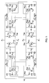
- the switches (often called disconnectors) H i5 and H i6 , with i having a value of 1 to 4, are always in the closed position except in the case of failure of certain elements of the system as will be seen later.
- the two motors M1 and M3 are connected in parallel between the points P1 and P3, and the two motors M2 and M4 are connected in parallel between the points P2 and P4.
- Each motor is supplied by a voltage received across a charge capacitor U1 for the motor M1, U2 for the M2, U3 for M3 and U4 for M4.
- the circuit supplying each capacitor associated with a motor mainly consists of a pair of voltage converters.
- Each of these voltage converters is of the GTO thyristor type which makes it possible to impose the output voltage collected at their midpoint by means of control signals applied to the triggers of the thyristors.
- the trigger of each of the 2 thyristors of the converter is Controlled in opposite fashion by a fixed frequency logic signal modulated in pulse width with an average value between 0 and 1, which makes it possible to have an output voltage value which is a function of the pulse width of the signal control applied to the triggers of the thyristors.
- the locomotive can be located in an area where the power supply is AC, for example from 25kV to 50Hz.
- the two converters of the same pair of converters are combined to form a four-quadrant converter well known in the art.
- the two converters B11 and B12 are connected at their midpoints, when the switch CT1 is closed, by means of the secondary winding S1 of a transformer whose primary winding is directly connected to the power source in alternating current.
- the switches CT2, CT3 and CT4 are closed, and the midpoints of the other pairs of converters are connected by the secondary windings S2, S3 and S4 of the same transformer whose primary winding is supplied by the source of AC power supply received by the catenary.
- the four motors are connected in parallel by closing the switches H13, H23, H33 and H43 so that the supply voltages of the motors U1, U2, U3 and U4 are identical. This allows, by interleaving the cuts of the converters B i1 , B i2 , to reduce the effective current in the capacitors C i .
- the converters are made to operate as voltage-reducing choppers.
- the midpoint of the voltage converter B11 and the midpoint of the voltage converter B12 are both connected by closing the switch H12 to the line corresponding to the potential point P4 via the inductors L11 and L12.
- the midpoint of the voltage converter B21 and the midpoint of the voltage converter B22 are both connected by closing the switch H22 to the line corresponding to the point of potential P3 via the respective inductances L21 and L22.
- the midpoint of the voltage converter B31 and the midpoint of the voltage converter B32 are both connected, by closing the switch H32, to the line corresponding to the potential P4 via the respective inductances L31 and L32; and the midpoints of the voltage converters B41 and B42 are connected, by closing the switch H42, to the line corresponding to the point of potential P3 via the respective inductances L41 and L42.
- the voltage received from the DC power source is UE between the potential points P1 and P2, the latter possibly being grounded. Due to the above-described arrangement of converters into voltage-reducing choppers, the points P3 and P4 are found at intermediate potentials between O and 3kV.
- the converter B11 supplies a voltage at the output of the inductor L11 intended to charge the capacitor C2 at the voltage U2 with respect to the potential of P2, (which can be considered to be at 0), which is less than the voltage UE and depends on the width of the control pulses applied to the triggers of the thyristors making up the converters according to a coefficient between 0 and 1.
- the converters are made to operate as step-up choppers.
- the midpoints of the voltage converters B11 and B12 are interconnected and, by closing the switch H11 (H12 remaining open), to the line corresponding to the point of potential P2 via the respective inductances L11 and L12.
- the midpoints of the voltage converters B21 and B22 are interconnected and, by closing the switch H21 (H22 remaining open), to the line corresponding to the point of potential P1 via the respective inductances L21 and L22.
- the midpoints of the voltage converters B31 and B32 are interconnected and by closing switch H31 at the corresponding line at the point of potential P2 via the respective inductors L31 and L32; and the midpoints of the converters B41 and B42 are interconnected and, thanks to the closing of the switch H41, to the line corresponding to the point of potential P1 via the respective inductances L41 and L42.
- the converter B21 in this case supplies a charging voltage of the capacitor U1 which is greater than the input voltage UE and which depends on the width of the control pulses applied to the triggers of the thyristors making up the converter and applying a coefficient a between 0 and 1 and such that U1.
- the distribution preferably adopted for the motors consists in having the motors M1 and M2 on one bogie and the motors M3 and M4 on the other bogie. But it goes without saying that other distributions of the motors are possible without departing from the scope of the invention.
- each additional branch of two motors comprises voltage converter elements, inductors, switches, identical to those which are in the branch composed of the motors M1 and M2.
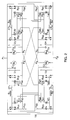
- each motor is supplied with a voltage received across a charge capacitor U1 for the motor M1, U2 for M2, U3 for M3 and U4 for M4.
- each capacitor associated with a motor is the same as in the first embodiment.
- thyristors is the preferred implementation mode for the choice of voltage converters, it is clear that any other switching system fulfilling the same function as the thyristors could be used.
- the connection of the converters is the same as in the first embodiment, that is to say that the switches or disconnectors CT i and H i3 , with i from 1 to 4, are closed while the switches H i1 and H i2 are all open.
- the operation is the same as in the first embodiment.
- the converters are made to operate as voltage-reducing choppers.
- the midpoint of the voltage converter B11 is connected, by closing the switch H12, to the line corresponding to the point of potential P4 via the inductance L11, and the midpoint of the voltage converter B12 is connected, by closing the switch H14, to the line corresponding to the point of potential P6 via the inductor L12.
- the midpoint of the voltage converter B21 is connected, by closing the switch H22, to the line corresponding to the point of potential P3 via the inductance L21; and the midpoint of the voltage converter B22 is connected by closing the switch H24, to the line corresponding to the point of potential P5 via the inductance L22.
- the midpoint of the voltage converter B31 is connected, by closing the switch H32, to the line corresponding to the point of potential P6 via the inductance L31; and the midpoint of the voltage converter B32 is connected, by closing the switch H34, to the line corresponding to the point of potential P4 via the inductance L32.
- the midpoint of the voltage converter B41 is connected, by closing the switch H42, to the line corresponding to the point of potential P5 via the inductance L41; and the midpoint of the voltage converter B42 is connected, by closing the switch H44 to the line corresponding to the point of potential P3 via the inductance L42.
- the voltage received from the DC power source is UE between the potential points P1 and P2, the latter possibly being grounded. Because the converters of the assembly illustrated in FIG. 2 are voltage-reducing choppers, the points P3, P4, P5 and P6 are at intermediate potentials between P1 and P2. The operation of converters into voltage-reducing choppers, known, has already been recalled with reference to FIG. 1 and it is therefore unnecessary to do it again.
- the converters are fitted to operate as step-up choppers. In this case, it is unnecessary to describe again the connections made since they are the same as the connections made in the first embodiment described with reference to FIG. 1, when the converters are used as step-up choppers.
- the distribution preferably adopted for the motors consists in having the motors M1 and M2 on one bogie and the motors M3 and M4 on the other bogie. But it goes without saying that other distributions of the motors are possible without departing from the scope of the invention.
- connections causing the converters to operate as step-up choppers are not a problem in the case of the addition of two motors since the connections are made between the pairs of converters associated with the two additional motors.
- the connections (not shown) to obtain the mounting of the converters into step-up choppers are between group 1 and group 2, between group 3 and group 4, ... between group 2N-1 and the group 2N.
Landscapes
- Engineering & Computer Science (AREA)
- Power Engineering (AREA)
- Life Sciences & Earth Sciences (AREA)
- Sustainable Development (AREA)
- Sustainable Energy (AREA)
- Transportation (AREA)
- Mechanical Engineering (AREA)
- Electric Propulsion And Braking For Vehicles (AREA)
- Control Of Multiple Motors (AREA)
Applications Claiming Priority (2)
| Application Number | Priority Date | Filing Date | Title |
|---|---|---|---|
| FR9314923 | 1993-12-13 | ||
| FR9314923A FR2713565B1 (fr) | 1993-12-13 | 1993-12-13 | Système d'alimentation multicourant à haute disponibilité pour engin de locomotive ferroviaire. |
Publications (2)
| Publication Number | Publication Date |
|---|---|
| EP0657321A1 true EP0657321A1 (de) | 1995-06-14 |
| EP0657321B1 EP0657321B1 (de) | 1998-01-28 |
Family
ID=9453850
Family Applications (1)
| Application Number | Title | Priority Date | Filing Date |
|---|---|---|---|
| EP94402836A Expired - Lifetime EP0657321B1 (de) | 1993-12-13 | 1994-12-09 | Mehrfachstromversorgungssystem mit hoher Verfügbarkeit für eine Lokomotive |
Country Status (10)
| Country | Link |
|---|---|
| US (1) | US5629591A (de) |
| EP (1) | EP0657321B1 (de) |
| JP (1) | JPH07203604A (de) |
| KR (1) | KR950022004A (de) |
| CN (1) | CN1107430A (de) |
| CA (1) | CA2137895A1 (de) |
| DE (1) | DE69408290T2 (de) |
| ES (1) | ES2113069T3 (de) |
| FR (1) | FR2713565B1 (de) |
| TW (1) | TW263628B (de) |
Cited By (2)
| Publication number | Priority date | Publication date | Assignee | Title |
|---|---|---|---|---|
| WO1997023947A1 (fr) * | 1995-12-21 | 1997-07-03 | Yves Niel | Dispositif pour augmenter la vitesse initialement prevue d'un moteur a courant continu |
| EP0756221A3 (de) * | 1995-07-21 | 1998-01-07 | ABB Daimler-Benz Transportation (Italia) S.p.A. | Vorrichtung und Verfahren zur Spannungsregelung in Stromkreisen für Transportfahrzeuge |
Families Citing this family (15)
| Publication number | Priority date | Publication date | Assignee | Title |
|---|---|---|---|---|
| FR2752781B1 (fr) * | 1996-09-03 | 1998-10-02 | Gec Alsthom Transport Sa | Dispositif et procede d'alimentation sous tension continue d'une chaine de traction au moyen de convertisseurs a partir de differentes tensions alternatives ou continues |
| JP4187308B2 (ja) * | 1998-06-16 | 2008-11-26 | 日本オーチス・エレベータ株式会社 | 可変速駆動装置 |
| DE19841132A1 (de) * | 1998-09-09 | 2000-03-16 | Abb Daimler Benz Transp | Modular aufgebaute Schaltungsanordnung, insbesondere für einen Antrieb eines Schienenfahrzeugs |
| AT500328B1 (de) * | 2002-02-07 | 2010-03-15 | Elin Ebg Traction Gmbh | Fahrzeug mit einem elektrischen antrieb und verfahren zum betrieb eines solchen fahrzeuges |
| EP1750361A1 (de) * | 2005-08-03 | 2007-02-07 | ABB Research Ltd | Anordnung eines Multilevel-Converters und ihre Verwendung |
| US20070149675A1 (en) | 2005-12-26 | 2007-06-28 | Industrial Technology Research Institute | Organic polymer/inorganic particles composite materials |
| CN101397500B (zh) * | 2007-09-27 | 2011-10-12 | 财团法人工业技术研究院 | 多层结构防火材料 |
| JP5017163B2 (ja) * | 2008-04-01 | 2012-09-05 | 株式会社日立製作所 | 鉄道車両の駆動装置 |
| KR100932972B1 (ko) * | 2008-05-06 | 2009-12-21 | 현대로템 주식회사 | 전동차의 인버터 고장 시 운행 방법 |
| JP5545103B2 (ja) * | 2010-08-02 | 2014-07-09 | 富士電機株式会社 | 電気車用駆動回路 |
| JP2014527937A (ja) * | 2011-09-25 | 2014-10-23 | イリノイ トゥール ワークス インコーポレイティド | 航空機のカート形汎用地上支援装置用のマルチ電圧電源 |
| CN102923133A (zh) * | 2012-10-26 | 2013-02-13 | 山东科技大学 | 一种矿用锂离子蓄电池电机车动力总成系统 |
| CN109318720B (zh) * | 2017-12-13 | 2022-02-11 | 中车长春轨道客车股份有限公司 | 一种多制式动车组高压供电系统及列车 |
| JP7774079B2 (ja) * | 2022-01-17 | 2025-11-20 | 株式会社日立製作所 | 列車制御システム、車上制御装置、及び列車制御方法 |
| CN117767774A (zh) * | 2023-06-27 | 2024-03-26 | 浙大城市学院 | 一种兼容中压直流制式的双流制可重构网侧变流器及其控制方法 |
Citations (2)
| Publication number | Priority date | Publication date | Assignee | Title |
|---|---|---|---|---|
| EP0383971A1 (de) * | 1989-02-22 | 1990-08-29 | Siemens Aktiengesellschaft | Einspeiseschaltung für eine Mehrsystemlokomotive |
| EP0514580A1 (de) * | 1991-05-24 | 1992-11-25 | Siemens Aktiengesellschaft | Umrichteranordnung |
Family Cites Families (5)
| Publication number | Priority date | Publication date | Assignee | Title |
|---|---|---|---|---|
| US3718846A (en) * | 1971-04-13 | 1973-02-27 | Borg Warner | Variable speed plural motor control system with incremental speed synchronization |
| US4263535A (en) * | 1978-09-29 | 1981-04-21 | Bucyrus-Erie Company | Motor drive system for an electric mining shovel |
| JPS6152179A (ja) * | 1984-08-22 | 1986-03-14 | Toshiba Corp | 電動機駆動用電源装置 |
| US4647824A (en) * | 1985-04-19 | 1987-03-03 | Kollmorgen Technologies Corp. | Output voltage control for a DC servo amplifier |
| US4841202A (en) * | 1987-12-28 | 1989-06-20 | Sundstrand Corporation | Speed-limited electrically compensated constant speed drive |
-
1993
- 1993-12-13 FR FR9314923A patent/FR2713565B1/fr not_active Expired - Fee Related
-
1994
- 1994-12-02 TW TW083111238A patent/TW263628B/zh active
- 1994-12-09 CN CN94112943A patent/CN1107430A/zh active Pending
- 1994-12-09 EP EP94402836A patent/EP0657321B1/de not_active Expired - Lifetime
- 1994-12-09 ES ES94402836T patent/ES2113069T3/es not_active Expired - Lifetime
- 1994-12-09 DE DE69408290T patent/DE69408290T2/de not_active Expired - Fee Related
- 1994-12-12 US US08/355,337 patent/US5629591A/en not_active Expired - Fee Related
- 1994-12-12 CA CA002137895A patent/CA2137895A1/fr not_active Abandoned
- 1994-12-13 JP JP6309275A patent/JPH07203604A/ja active Pending
- 1994-12-13 KR KR1019940033876A patent/KR950022004A/ko not_active Abandoned
Patent Citations (2)
| Publication number | Priority date | Publication date | Assignee | Title |
|---|---|---|---|---|
| EP0383971A1 (de) * | 1989-02-22 | 1990-08-29 | Siemens Aktiengesellschaft | Einspeiseschaltung für eine Mehrsystemlokomotive |
| EP0514580A1 (de) * | 1991-05-24 | 1992-11-25 | Siemens Aktiengesellschaft | Umrichteranordnung |
Non-Patent Citations (1)
| Title |
|---|
| G. WIEGNER: "GTO-STROMRICHTER FÜR BAHNEN", ZEV GLASERS ANNALEN, vol. 113, no. 6/7, July 1989 (1989-07-01), DE, pages 259 - 272 * |
Cited By (2)
| Publication number | Priority date | Publication date | Assignee | Title |
|---|---|---|---|---|
| EP0756221A3 (de) * | 1995-07-21 | 1998-01-07 | ABB Daimler-Benz Transportation (Italia) S.p.A. | Vorrichtung und Verfahren zur Spannungsregelung in Stromkreisen für Transportfahrzeuge |
| WO1997023947A1 (fr) * | 1995-12-21 | 1997-07-03 | Yves Niel | Dispositif pour augmenter la vitesse initialement prevue d'un moteur a courant continu |
Also Published As
| Publication number | Publication date |
|---|---|
| DE69408290D1 (de) | 1998-03-05 |
| CA2137895A1 (fr) | 1995-06-14 |
| TW263628B (de) | 1995-11-21 |
| DE69408290T2 (de) | 1998-05-14 |
| FR2713565A1 (fr) | 1995-06-16 |
| FR2713565B1 (fr) | 1996-01-19 |
| ES2113069T3 (es) | 1998-04-16 |
| KR950022004A (ko) | 1995-07-26 |
| EP0657321B1 (de) | 1998-01-28 |
| CN1107430A (zh) | 1995-08-30 |
| JPH07203604A (ja) | 1995-08-04 |
| US5629591A (en) | 1997-05-13 |
Similar Documents
| Publication | Publication Date | Title |
|---|---|---|
| EP0657321B1 (de) | Mehrfachstromversorgungssystem mit hoher Verfügbarkeit für eine Lokomotive | |
| CA2213856C (fr) | Dispositif et procede d'alimentation sous tension continue d'une chaine de traction au moyen de convertisseurs a partir de differentes tensions alternatives ou continues | |
| CA2638224C (fr) | Procede d'alimentation de charges auxiliaires de secours, convertisseur auxiliare et vehicule ferroviaire pour ce procede | |
| EP3944980B1 (de) | Triebwagengruppe aus einer lokomotive und einem tender, entsprechendes verfahren | |
| CA2145966A1 (fr) | Installation de transport a cable tracteur et a moteur embarque | |
| EP1420976A1 (de) | Elektrische mehrspannungsversorgung für ein schienenfahrzeug | |
| EP0147280B1 (de) | Speiseverfahren und -vorrichtung für eine Last, insbesondere einen Gleichstrommotor für Doppelspannungseisenbahnlokomotiven | |
| EP0811522B1 (de) | Antriebsystem mit mehrfacher Bestromung | |
| FR3049130B1 (fr) | Systeme de conversion d'energie electrique, appareil de stockage d'energie electrique et chaine de traction pour un vehicule ferroviaire | |
| EP3755569B1 (de) | Bordnetz zur umwandlung elektrischer energie | |
| FR3081395A1 (fr) | Architecture de traction electrique basse tension pour vehicule automobile autonome | |
| FR3106944A1 (fr) | Dispositif d’alimentation en énergie électrique pour un circuit triphasé et un circuit monophasé, chaîne de conversion d’énergie auxiliaire et véhicule électrique associés | |
| EP3860875B1 (de) | Bordsystem und verfahren zur umwandlung von mittelspannungsleistung für ein transportfahrzeug | |
| FR2930083A1 (fr) | Reseau electrique d'un aeronef | |
| EP3915822A1 (de) | Verfahren zur stromversorgung einer anordnung von fahrmotoren an bord eines fahrzeugs, elektronische vorrichtung zur leistungssteuerung und entsprechende anordnung von fahrmotoren | |
| FR3099008A1 (fr) | Système embarqué et procédé de conversion de puissance électrique pour un engin mobile de transport | |
| EP3693204B1 (de) | Stromversorgungssystem für schienenfahrzeug | |
| EP4043272A1 (de) | Triebfahrzeug mit speichervorrichtung für elektrische energie | |
| EP3536537B1 (de) | Trennschalter zur neukonfiguration der stromversorgung eines elektrischen antriebs eines fahrzeugs, insbesondere eines eisenbahnfahrzeugs | |
| CA2258343C (fr) | Chaine de traction en tension comportant des bus d'alimentation d'un engin de traction electrique | |
| FR3139053A1 (fr) | Ensemble de recharge d’une batterie electrique de traction | |
| FR3138561A1 (fr) | Ensemble electrique pour securiser un reseau electrique haute tension d’un vehicule automobile electrifie | |
| WO2023209296A1 (fr) | Ensemble de recharge électrique pour véhicule automobile électrifié | |
| WO2025008284A1 (fr) | Train de travaux ferroviaires comportant des véhicules de travaux | |
| EP4577427A1 (de) | Ladeanordnung zum laden einer elektrischen traktionsbatterie |
Legal Events
| Date | Code | Title | Description |
|---|---|---|---|
| PUAI | Public reference made under article 153(3) epc to a published international application that has entered the european phase |
Free format text: ORIGINAL CODE: 0009012 |
|
| AK | Designated contracting states |
Kind code of ref document: A1 Designated state(s): BE CH DE ES FR GB IT LI LU NL PT SE |
|
| 17P | Request for examination filed |
Effective date: 19951106 |
|
| GRAG | Despatch of communication of intention to grant |
Free format text: ORIGINAL CODE: EPIDOS AGRA |
|
| 17Q | First examination report despatched |
Effective date: 19970418 |
|
| GRAG | Despatch of communication of intention to grant |
Free format text: ORIGINAL CODE: EPIDOS AGRA |
|
| GRAH | Despatch of communication of intention to grant a patent |
Free format text: ORIGINAL CODE: EPIDOS IGRA |
|
| GRAH | Despatch of communication of intention to grant a patent |
Free format text: ORIGINAL CODE: EPIDOS IGRA |
|
| GRAA | (expected) grant |
Free format text: ORIGINAL CODE: 0009210 |
|
| AK | Designated contracting states |
Kind code of ref document: B1 Designated state(s): BE CH DE ES FR GB IT LI LU NL PT SE |
|
| ITF | It: translation for a ep patent filed | ||
| REG | Reference to a national code |
Ref country code: CH Ref legal event code: NV Representative=s name: GEC ALSTHOM SALES NETWORK SA Ref country code: CH Ref legal event code: EP |
|
| GBT | Gb: translation of ep patent filed (gb section 77(6)(a)/1977) |
Effective date: 19980129 |
|
| REF | Corresponds to: |
Ref document number: 69408290 Country of ref document: DE Date of ref document: 19980305 |
|
| REG | Reference to a national code |
Ref country code: ES Ref legal event code: FG2A Ref document number: 2113069 Country of ref document: ES Kind code of ref document: T3 |
|
| REG | Reference to a national code |
Ref country code: PT Ref legal event code: SC4A Free format text: AVAILABILITY OF NATIONAL TRANSLATION Effective date: 19980302 |
|
| PLBE | No opposition filed within time limit |
Free format text: ORIGINAL CODE: 0009261 |
|
| STAA | Information on the status of an ep patent application or granted ep patent |
Free format text: STATUS: NO OPPOSITION FILED WITHIN TIME LIMIT |
|
| 26N | No opposition filed | ||
| REG | Reference to a national code |
Ref country code: GB Ref legal event code: IF02 |
|
| PGFP | Annual fee paid to national office [announced via postgrant information from national office to epo] |
Ref country code: NL Payment date: 20081216 Year of fee payment: 15 Ref country code: LU Payment date: 20081219 Year of fee payment: 15 Ref country code: CH Payment date: 20081215 Year of fee payment: 15 |
|
| PGFP | Annual fee paid to national office [announced via postgrant information from national office to epo] |
Ref country code: PT Payment date: 20081126 Year of fee payment: 15 Ref country code: ES Payment date: 20081217 Year of fee payment: 15 |
|
| PGFP | Annual fee paid to national office [announced via postgrant information from national office to epo] |
Ref country code: SE Payment date: 20081212 Year of fee payment: 15 Ref country code: IT Payment date: 20081220 Year of fee payment: 15 |
|
| PGFP | Annual fee paid to national office [announced via postgrant information from national office to epo] |
Ref country code: FR Payment date: 20081212 Year of fee payment: 15 |
|
| PGFP | Annual fee paid to national office [announced via postgrant information from national office to epo] |
Ref country code: DE Payment date: 20081219 Year of fee payment: 15 |
|
| PGFP | Annual fee paid to national office [announced via postgrant information from national office to epo] |
Ref country code: GB Payment date: 20081216 Year of fee payment: 15 |
|
| PGFP | Annual fee paid to national office [announced via postgrant information from national office to epo] |
Ref country code: BE Payment date: 20090130 Year of fee payment: 15 |
|
| REG | Reference to a national code |
Ref country code: PT Ref legal event code: MM4A Free format text: LAPSE DUE TO NON-PAYMENT OF FEES Effective date: 20100609 |
|
| BERE | Be: lapsed |
Owner name: S.A. *GEC ALSTHOM TRANSPORT Effective date: 20091231 |
|
| REG | Reference to a national code |
Ref country code: NL Ref legal event code: V1 Effective date: 20100701 |
|
| EUG | Se: european patent has lapsed | ||
| PG25 | Lapsed in a contracting state [announced via postgrant information from national office to epo] |
Ref country code: PT Free format text: LAPSE BECAUSE OF NON-PAYMENT OF DUE FEES Effective date: 20100609 |
|
| REG | Reference to a national code |
Ref country code: CH Ref legal event code: PL |
|
| GBPC | Gb: european patent ceased through non-payment of renewal fee |
Effective date: 20091209 |
|
| REG | Reference to a national code |
Ref country code: FR Ref legal event code: ST Effective date: 20100831 |
|
| PG25 | Lapsed in a contracting state [announced via postgrant information from national office to epo] |
Ref country code: NL Free format text: LAPSE BECAUSE OF NON-PAYMENT OF DUE FEES Effective date: 20100701 Ref country code: LI Free format text: LAPSE BECAUSE OF NON-PAYMENT OF DUE FEES Effective date: 20091231 Ref country code: FR Free format text: LAPSE BECAUSE OF NON-PAYMENT OF DUE FEES Effective date: 20091231 Ref country code: CH Free format text: LAPSE BECAUSE OF NON-PAYMENT OF DUE FEES Effective date: 20091231 Ref country code: BE Free format text: LAPSE BECAUSE OF NON-PAYMENT OF DUE FEES Effective date: 20091231 |
|
| PG25 | Lapsed in a contracting state [announced via postgrant information from national office to epo] |
Ref country code: DE Free format text: LAPSE BECAUSE OF NON-PAYMENT OF DUE FEES Effective date: 20100701 |
|
| PG25 | Lapsed in a contracting state [announced via postgrant information from national office to epo] |
Ref country code: GB Free format text: LAPSE BECAUSE OF NON-PAYMENT OF DUE FEES Effective date: 20091209 |
|
| REG | Reference to a national code |
Ref country code: ES Ref legal event code: FD2A Effective date: 20110310 |
|
| PG25 | Lapsed in a contracting state [announced via postgrant information from national office to epo] |
Ref country code: IT Free format text: LAPSE BECAUSE OF NON-PAYMENT OF DUE FEES Effective date: 20091209 |
|
| PG25 | Lapsed in a contracting state [announced via postgrant information from national office to epo] |
Ref country code: LU Free format text: LAPSE BECAUSE OF NON-PAYMENT OF DUE FEES Effective date: 20091209 |
|
| PG25 | Lapsed in a contracting state [announced via postgrant information from national office to epo] |
Ref country code: SE Free format text: LAPSE BECAUSE OF NON-PAYMENT OF DUE FEES Effective date: 20091210 |
|
| PG25 | Lapsed in a contracting state [announced via postgrant information from national office to epo] |
Ref country code: ES Free format text: LAPSE BECAUSE OF NON-PAYMENT OF DUE FEES Effective date: 20110309 |
|
| PG25 | Lapsed in a contracting state [announced via postgrant information from national office to epo] |
Ref country code: ES Free format text: LAPSE BECAUSE OF NON-PAYMENT OF DUE FEES Effective date: 20091210 |