EP0657329B1 - Dispositif de sac gonflable - Google Patents
Dispositif de sac gonflable Download PDFInfo
- Publication number
- EP0657329B1 EP0657329B1 EP94114815A EP94114815A EP0657329B1 EP 0657329 B1 EP0657329 B1 EP 0657329B1 EP 94114815 A EP94114815 A EP 94114815A EP 94114815 A EP94114815 A EP 94114815A EP 0657329 B1 EP0657329 B1 EP 0657329B1
- Authority
- EP
- European Patent Office
- Prior art keywords
- air bag
- bag
- gas
- occupant
- sub
- Prior art date
- Legal status (The legal status is an assumption and is not a legal conclusion. Google has not performed a legal analysis and makes no representation as to the accuracy of the status listed.)
- Expired - Lifetime
Links
Images

Classifications
-
- B—PERFORMING OPERATIONS; TRANSPORTING
- B60—VEHICLES IN GENERAL
- B60R—VEHICLES, VEHICLE FITTINGS, OR VEHICLE PARTS, NOT OTHERWISE PROVIDED FOR
- B60R21/00—Arrangements or fittings on vehicles for protecting or preventing injuries to occupants or pedestrians in case of accidents or other traffic risks
- B60R21/02—Occupant safety arrangements or fittings, e.g. crash pads
- B60R21/16—Inflatable occupant restraints or confinements designed to inflate upon impact or impending impact, e.g. air bags
- B60R21/23—Inflatable members
- B60R21/231—Inflatable members characterised by their shape, construction or spatial configuration
- B60R21/233—Inflatable members characterised by their shape, construction or spatial configuration comprising a plurality of individual compartments; comprising two or more bag-like members, one within the other
- B60R2021/23324—Inner walls crating separate compartments, e.g. communicating with vents
- B60R2021/23332—Inner walls crating separate compartments, e.g. communicating with vents using independent bags, one within the other
-
- B—PERFORMING OPERATIONS; TRANSPORTING
- B60—VEHICLES IN GENERAL
- B60R—VEHICLES, VEHICLE FITTINGS, OR VEHICLE PARTS, NOT OTHERWISE PROVIDED FOR
- B60R21/00—Arrangements or fittings on vehicles for protecting or preventing injuries to occupants or pedestrians in case of accidents or other traffic risks
- B60R21/02—Occupant safety arrangements or fittings, e.g. crash pads
- B60R21/16—Inflatable occupant restraints or confinements designed to inflate upon impact or impending impact, e.g. air bags
- B60R21/26—Inflatable occupant restraints or confinements designed to inflate upon impact or impending impact, e.g. air bags characterised by the inflation fluid source or means to control inflation fluid flow
- B60R2021/26058—Inflatable occupant restraints or confinements designed to inflate upon impact or impending impact, e.g. air bags characterised by the inflation fluid source or means to control inflation fluid flow using a combination of inflators
-
- B—PERFORMING OPERATIONS; TRANSPORTING
- B60—VEHICLES IN GENERAL
- B60R—VEHICLES, VEHICLE FITTINGS, OR VEHICLE PARTS, NOT OTHERWISE PROVIDED FOR
- B60R21/00—Arrangements or fittings on vehicles for protecting or preventing injuries to occupants or pedestrians in case of accidents or other traffic risks
- B60R21/02—Occupant safety arrangements or fittings, e.g. crash pads
- B60R21/16—Inflatable occupant restraints or confinements designed to inflate upon impact or impending impact, e.g. air bags
- B60R21/26—Inflatable occupant restraints or confinements designed to inflate upon impact or impending impact, e.g. air bags characterised by the inflation fluid source or means to control inflation fluid flow
- B60R21/264—Inflatable occupant restraints or confinements designed to inflate upon impact or impending impact, e.g. air bags characterised by the inflation fluid source or means to control inflation fluid flow using instantaneous generation of gas, e.g. pyrotechnic
- B60R21/2644—Inflatable occupant restraints or confinements designed to inflate upon impact or impending impact, e.g. air bags characterised by the inflation fluid source or means to control inflation fluid flow using instantaneous generation of gas, e.g. pyrotechnic using only solid reacting substances, e.g. pellets, powder
- B60R2021/2648—Inflatable occupant restraints or confinements designed to inflate upon impact or impending impact, e.g. air bags characterised by the inflation fluid source or means to control inflation fluid flow using instantaneous generation of gas, e.g. pyrotechnic using only solid reacting substances, e.g. pellets, powder comprising a plurality of combustion chambers or sub-chambers
-
- B—PERFORMING OPERATIONS; TRANSPORTING
- B60—VEHICLES IN GENERAL
- B60R—VEHICLES, VEHICLE FITTINGS, OR VEHICLE PARTS, NOT OTHERWISE PROVIDED FOR
- B60R21/00—Arrangements or fittings on vehicles for protecting or preventing injuries to occupants or pedestrians in case of accidents or other traffic risks
- B60R21/02—Occupant safety arrangements or fittings, e.g. crash pads
- B60R21/16—Inflatable occupant restraints or confinements designed to inflate upon impact or impending impact, e.g. air bags
- B60R21/20—Arrangements for storing inflatable members in their non-use or deflated condition; Arrangement or mounting of air bag modules or components
- B60R21/203—Arrangements for storing inflatable members in their non-use or deflated condition; Arrangement or mounting of air bag modules or components in steering wheels or steering columns
Definitions
- the present invention relates to an air bag device, more particularly, to an air bag device which can prevent an occupant from bumping against a steering wheel, absorb an impact force applied to the occupant's head and chest and reliably protect the occupant.
- an air bag device is adopted to various kinds of vehicles as a passive occupant protection system for efficiently protecting an occupant from the action of the impact force at a collision.
- the purpose of the air bag device is to prevent the occupant from a secondary collision in a cabin by receiving the occupant's body, particularly, the head and chest with a bag shaped cushion filled with gas during a collision.
- a position D1 of an occupant in a driver's seat moves to the position D2 at a collision, the occupant is protected by being pushed to the deployed air bag 54 at his chest and head. Thereby, the occupant is protected from the secondary collision, that is, the occupant plunges into and bumps against a steering wheel or a windshield of the vehicle.
- an air bag device wherein the air bag device has a conventional air bag (hereinafter, the air bag shown by an alternate long and short dash line is called by "main bag”) and an air bag formed in a ring shape to cover a periphery of the steering wheel (hereinafter, the air bag formed in a ring shape and disposed a periphery of the main bag is called by "sub bag”) and both air bags are deployed (See Journal of Technical Disclosure published by Japan Institute of Invention and Innovation, Technical Disclosure No. 88-15251, Published Unexamined Utility model No. 1989-122349).
- main bag the air bag shown by an alternate long and short dash line
- sub bag the air bag formed in a ring shape to cover a periphery of the steering wheel
- the sub bag 61 is folded and accommodated in a hollow rim 62 of the steering wheel 70 and gas for inflation and deployment is introduced into the sub bag 61 through a spoke 63 acting also as a gas pipe as shown by the arrow.
- the hollow rim 62 has a tear line 64 is formed at a predetermined position thereof.
- the tear line 64 breaks and portions 62a of the hollow rim 62 is expanded in a direction of the arrow B, then the sub bag 61 accommodated inside the hollow rim 62 expands like a rush.
- the main bag 66 expands and deploys so as to prevent the occupant moving in a direction of the arrow A from bumping against the steering wheel 70 and to protect the occupant's head and chest from an impact.
- the rim 62 is a portion which the driver always holds to steer, the rim 62 should have rigidity and strength not to break even if the rim is gripped hard.
- the tear line formed on the periphery of the rim 62 should be formed as a weak part to easily break when the internal pressure is applied by introducing gas. Actually, it is quite difficult to make such a rim 62 structured to be compatible as mentioned above.
- DE-A-22 48 393 discloses an air bag device showing the features mentioned in the preamble of present claim 1.
- an air bag device is described which is accommodated in a steering pad and comprises first and second air bags seamed together.
- the second air bag covers the steering pad and extends around the outer lower surface of the first air bag. This arrangement is not completely satisfactory with regard to the security and production of the air bag device.
- the invention provides an air bag device accommodated in a steering pad comprising:a first air bag receiving an occupant by the inflation and deployment during a collision; and a second air bag seemed with a portion of said first air bag, and being inflatable in a ring shape to cover a surface of a steering wheel facing to the occupant, said second air bag having gas communicating holes to communicate gas with said first air bag, said second air bag being inflated by introducing gas from gas generating means connected to a gas inlet of said second air bag and said first air bag being inflated at the same time by introducing gas through the gas communicating holes.
- the second air bag is accommodated in the first air bag.
- the air bag device comprises a first air bag receiving an occupant by the inflation and deployment during a collision, and a second air bag seemed with a portion of the first air bag and being inflatable in a ring shape to cover a surface of a steering wheel facing to the occupant so that the air bag device can prevent the occupant form bumping against the steering wheel by the second air bag and can protect the occupant's head and chest by the first air bag.
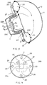
- Fig. 3 is a sectional view showing an example of an air bag device according to an embodiment of the invention.
- the steering center pad 1 is fixed to an end of a steering column 3 and integrally structured with a steering wheel 2 through spokes (not shown) at a substantially central portion of the steering wheel 2.
- the steering center pad 1 rotates with the steering wheel 2 around the steering column 3 during steering.
- a retainer plate is fixed in the steering center pad 1 by a fixing screw (not shown).
- the retainer plate is for fixedly supporting an inflator 5 as a gas source of the air bag device in the center pad 1.
- the inflator 5 is an equivalent with one of a conventional air bag device.
- the inflator 5 has a gas outlet 5a formed in a side surface of a rough flat cylindrical shaped body thereof to spout reaction gas from the gas outlet 5a to inflate and deploy a folded air bag 10 (will be described in detail) in a predetermined shape.
- the air bag 10 comprises a main bag 11 as a first air bag and a sub bag 28 as a second air bag fixed to a portion of the main bag 11 and deploying in a ring shape at a position to cover the steering wheel 2 (hereinafter, the main bag and the sub bag are generically called the air bag 10).
- a nylon fabric of which an inner surface is coated by a silicone is employed as clothes for the main bag 11 and the sub bag 28.
- the nylon woven fabric is a fabric woven with fine threads of approximately 420 deniers so that the folded size of the air bag 10 is smaller.
- the main bag 11 and the sub bag 28 are inflated simultaneously with the reaction gas generated from the single inflator 5.
- Gas communicating holes 20 are provided in the connecting portion between the main bag 11 and the sub bag 28 as shown in Fig. 4. Thereby, the reaction gas spouted from the inflator 5 inflates the main bag 11 and the sub bag.
- the volume of the sub bag 28 is pretty smaller than one of the main bag 11.
- Each diameter of the gas communicating holes 20 of the sub bag 28 and main bag 11 is set in a suitable size to properly set for the inflation timing of the both bags.
- the number of the gas communicating holes 20 provided at a rough cross position centered the gas inlet 28a of the main bag 11 is four in this embodiment, the diameter and the number of the gas communicating holes may be freely chosen.
- the number of the gas communicating holes 20 is preferably from two to four to inflate the sub bag at a uniform pace.
- vent holes 27 are provided near the gas inlet 28a of the main bag 11.
- the vent holes 27 exhaust gas in the main bag 11 gradually when the occupant strongly bumps into the inflated main bag 11.
- the main bag 11 has a long buffer stroke so as to absorb an impact applied to the occupant's face or the like when the occupant bumps into the main bag 11.
- the gas in the main bag is exhausted through the vent holes 27 while the occupant bumps into the air bag so that the main bag 11 can absorb the impact and protect the occupant.
- the main bag 11 has no gas outlet hole such as the vent holes 27, the occupant tends to strongly rebound off the main bag 11 when the occupant collides with the main bag 11.
- Such a phenomenon is called a rebound phenomenon. If the rebound phenomenon of the air bag is severe, the air bag cannot work its function as an impact absorbing device.
- the sub bag 28 may not be provided with a measure for easing the rebound phenomenon. Because the sub bag normally has no vent hole, the sub bag is maintained the inflation condition in a rough ring shape with high internal pressure.
- the steering center pad 1 has a lid.
- the lid may be a resin molding product produced by molding urethane resin on a surface of an aluminum plate as a core of the resin molding product. Though a tear line is provided at a substantial central portion of the lid of the pad 1 facing the occupant, the lid is maintained its stiffness not to break by a normal horn operation and a light contact.
- the main bag 11 is inflated slightly to push the lid from the inside thereof.
- the tear line provided in the inner surface of the lid breaks so that the air bag 10 folded inside rushes out.
- the sub bag 28 has a gas inlet 28a to communicate the gas between the sub bag 28 and the main bag 11.
- a base portion 28B of the sub bag 28 is accommodated in the steering center pad 1.
- the gas inlet 28a provided in the base portion 28B connects with the inflator 5 at the lower side of the pad and maintains the airtightness.
- a sub bag gas path 26 formed in a rough cross shape is provided by seaming with the main bag 11 as shown in Fig. 4.
- the sub bag 28 is supplied with gas from the inflator 5 through the sub bag gas path 26.
- a peripheral edge of the base panel 28B is seamed with a ring panel 28A made of a ring shaped cloth.
- a ring panel 28A made of a ring shaped cloth.
- the pores are gas communicating holes 20 to the main bag 11 to introduce the gas supplied in the sub bag 28 to the main bag 11 to inflate the main bag 11.
- Vent holes 27 are provided out of the portion of the sub bag gas path 26.
- the vent holes 27 have the function described hereinbefore.
- the gas is introduced from the inflator 5 to inflate the sub bag 28 and into the main bag 11 through the gas communicating holes 20 to inflate the main bag 11 at substantially the same time. Therefore, the pressure in the sub bag 28 can be maintained higher than the pressure in the main bag 11. The sub bag 28 can prevent the occupant more reliably from colliding with the steering wheel.
- the base panel 28B of sub bag 28 is accommodated in the main bag 11 and the gas communicating holes are independently provided in the surface of a ring panel 28A accommodated in the main bag 11 so that the gas communicating holes are not seamed with the textile of the main bag 11 as shown in Fig. 3 in this embodiment.
- the structure as mentioned above can simplify a cutting form of the cloth for each bag and reduce the seaming portions thereby increase the productivity of the air bag.
- the volume of the main bag is increased because the sub bag 28 is accommodated in the main bag 11 in this embodiment.
- the capacity of the gas generation of the inflator is preferable to be set suitably. It is a secondary effect that the receiving area of the main bag 11 is wider.
- the air bag device can prevent the occupant from colliding with the steering wheel by means for reasonable cost and effectively acts the occupant protection function as an essential function of the air bag.
Landscapes
- Engineering & Computer Science (AREA)
- Mechanical Engineering (AREA)
- Air Bags (AREA)
Claims (1)
- Structure de coussin gonflable logée dans un support de volant (1), qui comprend :un premier coussin gonflable (11) qui reçoit un occupant quand il se déploie et se gonfle pendant une collision, etun deuxième coussin gonflable (28) soudé à une partie dudit premier coussin gonflable et pouvant être gonflé en forme de bague pour recouvrir la surface du volant (2) qui fait face à l'occupant,
ledit deuxième coussin gonflable comportant des trous (20) de passage de gaz servant à faire communiquer du gaz avec ledit premier coussin gonflable,
ledit deuxième coussin gonflable étant gonflé par introduction d'un gaz en provenance d'un moyen (5) de production de gaz couplé à une entrée de gaz (28a, 26) dudit deuxième coussin gonflable, et ledit premier coussin gonflable étant gonflé au même moment par introduction de gaz par lesdits trous (20) de passage de gaz,
caractérisé en ce que ledit deuxième coussin gonflable (28) est placé dans ledit premier coussin gonflable (11).
Applications Claiming Priority (2)
| Application Number | Priority Date | Filing Date | Title |
|---|---|---|---|
| JP340793/93 | 1993-12-08 | ||
| JP34079393A JP3352203B2 (ja) | 1993-12-08 | 1993-12-08 | エアバッグ装置 |
Publications (2)
| Publication Number | Publication Date |
|---|---|
| EP0657329A1 EP0657329A1 (fr) | 1995-06-14 |
| EP0657329B1 true EP0657329B1 (fr) | 1998-12-16 |
Family
ID=18340346
Family Applications (1)
| Application Number | Title | Priority Date | Filing Date |
|---|---|---|---|
| EP94114815A Expired - Lifetime EP0657329B1 (fr) | 1993-12-08 | 1994-09-20 | Dispositif de sac gonflable |
Country Status (4)
| Country | Link |
|---|---|
| US (1) | US5529337A (fr) |
| EP (1) | EP0657329B1 (fr) |
| JP (1) | JP3352203B2 (fr) |
| DE (1) | DE69415288T2 (fr) |
Families Citing this family (99)
| Publication number | Priority date | Publication date | Assignee | Title |
|---|---|---|---|---|
| DE19701709C2 (de) * | 1997-01-21 | 2000-07-20 | Bsrs Restraint Syst Gmbh | Knieschutzeinrichtung |
| GB2323569B (en) * | 1997-03-24 | 2001-05-09 | Autoliv Dev | Improvements in or relating to an air-bag arrangement |
| GB2334492B (en) * | 1997-11-28 | 2002-05-15 | Nihon Plast Co Ltd | Air bag, air bag apparatus, and steering wheel |
| DE19757410C2 (de) * | 1997-12-15 | 2001-01-25 | Petri Ag | Gassack für ein Airbagmodul |
| JPH11245759A (ja) * | 1998-03-06 | 1999-09-14 | Honda Motor Co Ltd | 運転席用エアバッグ装置 |
| JPH11255063A (ja) * | 1998-03-13 | 1999-09-21 | Takata Kk | エアバッグ及びエアバッグ装置 |
| DE29821621U1 (de) * | 1998-12-03 | 1999-01-28 | TRW Automotive Safety Systems GmbH, 63743 Aschaffenburg | Aufprall-Schutzvorrichtung für Kraftfahrzeuge |
| US6254121B1 (en) * | 1998-12-14 | 2001-07-03 | Breed Automotive Technology, Inc. | Chambered driver side air bag and module attachment method |
| JP2000313303A (ja) * | 1999-04-28 | 2000-11-14 | Nippon Plast Co Ltd | エアバッグ及びエアバッグ装置 |
| DE19923483A1 (de) * | 1999-05-21 | 2000-11-23 | Volkswagen Ag | Airbag für ein Kraftfahrzeug |
| DE19932696C1 (de) * | 1999-07-15 | 2000-09-07 | Daimler Chrysler Ag | Insassenschutzvorrichtung mit zumindest zwei mit Gas auffüllbaren Airbags |
| DE10109500A1 (de) * | 2000-03-03 | 2001-10-04 | Takata Corp | Kopfschutzkissen für Fahrzeuginsassen |
| US6554316B2 (en) | 2001-03-08 | 2003-04-29 | Autoliv Asp, Inc. | Multi-chamber airbag gas venting system |
| DE20109596U1 (de) | 2001-06-08 | 2001-10-18 | Trw Automotive Safety Sys Gmbh | Gassack für ein Fahrzeuginsassen-Rückhaltesystem |
| JP2003034208A (ja) * | 2001-07-24 | 2003-02-04 | Takata Corp | エアバッグ |
| JP2003160016A (ja) * | 2001-11-22 | 2003-06-03 | Takata Corp | 助手席用エアバッグ装置 |
| US6851706B2 (en) * | 2002-03-21 | 2005-02-08 | Autoliv Asp, Inc. | Side-impact, variable thickness vehicular airbag |
| DE20209659U1 (de) * | 2002-06-21 | 2002-10-31 | TRW Automotive Safety Systems GmbH & Co. KG, 63743 Aschaffenburg | Gassack |
| JP2004210257A (ja) * | 2002-12-18 | 2004-07-29 | Takata Corp | 頭部保護エアバッグ及び頭部保護エアバッグ装置 |
| DE10301715A1 (de) * | 2003-01-14 | 2004-07-29 | Takata-Petri Ag | Airbagsystem |
| US7140680B2 (en) * | 2003-01-22 | 2006-11-28 | L&P Property Management Company | Fold down seat lumbar support apparatus and method |
| JP4363179B2 (ja) * | 2003-01-23 | 2009-11-11 | タカタ株式会社 | エアバッグ及びエアバッグ装置 |
| JP4135515B2 (ja) * | 2003-01-23 | 2008-08-20 | タカタ株式会社 | エアバッグ装置 |
| JP4321228B2 (ja) * | 2003-11-14 | 2009-08-26 | タカタ株式会社 | エアバッグ及びエアバッグ装置 |
| JP4496794B2 (ja) * | 2004-01-28 | 2010-07-07 | トヨタ自動車株式会社 | エアバッグ装置 |
| JP2005247272A (ja) * | 2004-02-06 | 2005-09-15 | Takata Corp | エアバッグ装置 |
| JP2005231504A (ja) * | 2004-02-19 | 2005-09-02 | Takata Corp | 乗員保護装置 |
| JP4687105B2 (ja) * | 2004-12-28 | 2011-05-25 | タカタ株式会社 | エアバッグ装置 |
| US7942440B2 (en) * | 2005-12-22 | 2011-05-17 | Autoliv Asp, Inc. | Channel and diffuser airbag |
| EP1864871B1 (fr) | 2006-06-02 | 2008-12-03 | Toyoda Gosei Co., Ltd. | Dispositif d'airbag |
| JP4337850B2 (ja) * | 2006-08-25 | 2009-09-30 | トヨタ自動車株式会社 | 運転席用エアバッグ装置 |
| JP4241799B2 (ja) * | 2006-10-16 | 2009-03-18 | トヨタ自動車株式会社 | 車両用ステアリング装置 |
| US7654561B2 (en) * | 2008-03-01 | 2010-02-02 | Delphi Technologies, Inc. | Inflatable cushion for an airbag module |
| KR20090126087A (ko) * | 2008-06-03 | 2009-12-08 | 현대자동차주식회사 | 차량용 에어백 장치 |
| US8118325B2 (en) * | 2009-04-27 | 2012-02-21 | Autoliv Asp, Inc. | Inflatable knee airbags and internal tethers produced from single panels of material |
| US8777262B2 (en) | 2009-04-27 | 2014-07-15 | Autoliv Asp, Inc. | Airbag assemblies with stabilizer straps |
| US20100270782A1 (en) * | 2009-04-27 | 2010-10-28 | Autoliv Asp, Inc. | Inflatable knee airbag assemblies with bag straps for wrapping the airbags and optimizing deployment |
| US8500157B2 (en) | 2009-04-27 | 2013-08-06 | Autoliv Asp, Inc. | Knee airbag assemblies and related methods |
| US8083254B2 (en) * | 2009-04-27 | 2011-12-27 | Autoliv Asp, Inc. | Knee airbag assemblies configured for inflator insertion and inflator-mediated coupling to an airbag housing |
| US8297649B2 (en) * | 2009-07-16 | 2012-10-30 | Autoliv Asp, Inc. | Inflatable knee airbag having two chambers separated by an internal tether |
| US8272667B2 (en) * | 2009-11-03 | 2012-09-25 | Autoliv Asp, Inc. | Low-mount inflatable knee airbags having serial chambers |
| US20110148083A1 (en) * | 2009-12-21 | 2011-06-23 | Autoliv Asp, Inc. | Inflatable airbag assemblies having non-planar inflation gas deflectors |
| US8500155B2 (en) * | 2009-12-22 | 2013-08-06 | Autoliv Asp, Inc. | Inflatable airbag assembly with an integral cover |
| US8360464B2 (en) | 2010-08-31 | 2013-01-29 | Autoliv Asp, Inc. | Covers for inflatable knee airbag housings |
| US8297650B2 (en) | 2010-08-31 | 2012-10-30 | Autoliv Asp, Inc. | Inflatable knee airbag assemblies with articulating housings |
| JP5572597B2 (ja) | 2011-06-30 | 2014-08-13 | 富士重工業株式会社 | 乗員保護装置 |
| JP5377583B2 (ja) * | 2011-06-30 | 2013-12-25 | 富士重工業株式会社 | 乗員保護装置 |
| JP5377582B2 (ja) | 2011-06-30 | 2013-12-25 | 富士重工業株式会社 | 乗員保護装置 |
| DE102011109607A1 (de) * | 2011-08-05 | 2013-02-07 | GM Global Technology Operations LLC (n. d. Gesetzen des Staates Delaware) | Sicherheitseinrichtung für ein Kraftfahrzeug |
| US8540276B2 (en) | 2011-11-07 | 2013-09-24 | Autoliv Asp, Inc. | Inflatable knee airbag assemblies with cushion fold pattern |
| US8505963B1 (en) | 2012-02-24 | 2013-08-13 | Autoliv Asp, Inc. | Airbag assemblies with strap clamps |
| US8764057B1 (en) | 2013-01-17 | 2014-07-01 | Autoliv Asp, Inc. | Multi-chamber driver airbags |
| DE102013002982A1 (de) | 2013-02-20 | 2014-08-21 | Autoliv Development Ab | Gassacksystem für den Insassenschutz |
| US8876153B2 (en) * | 2013-02-27 | 2014-11-04 | Nissan North America, Inc. | Airbag assembly |
| US8840139B1 (en) | 2013-03-14 | 2014-09-23 | Autoliv Asp, Inc. | Airbag with deflector |
| US9010804B2 (en) | 2013-03-15 | 2015-04-21 | Autoliv Asp, Inc. | Airbag assemblies with constrained stabilizer straps |
| JP2015003675A (ja) * | 2013-06-21 | 2015-01-08 | トヨタ自動車株式会社 | 運転席用エアバッグ装置 |
| JP5880489B2 (ja) | 2013-06-25 | 2016-03-09 | トヨタ自動車株式会社 | 運転席用エアバッグ装置 |
| US9340176B2 (en) * | 2014-03-13 | 2016-05-17 | Ford Global Technologies, Llc | Passenger airbag with secondary chamber |
| GB2524292A (en) * | 2014-03-19 | 2015-09-23 | Ford Global Tech Llc | An airbag system |
| US9561774B2 (en) * | 2014-04-24 | 2017-02-07 | Ford Global Technologies, Llc | Winged driver airbag |
| CN105083204B (zh) * | 2014-05-23 | 2017-07-14 | 现代摩比斯株式会社 | 安全气囊模块 |
| JP6206357B2 (ja) * | 2014-08-25 | 2017-10-04 | トヨタ自動車株式会社 | 自動車用エアバッグ装置 |
| KR101664588B1 (ko) * | 2014-11-24 | 2016-10-11 | 현대자동차주식회사 | 차량용 조수석 에어백 장치 |
| JP6314897B2 (ja) * | 2015-04-09 | 2018-04-25 | トヨタ自動車株式会社 | 車両用運転席エアバッグ装置 |
| JP6274164B2 (ja) | 2015-07-28 | 2018-02-07 | トヨタ自動車株式会社 | 運転席用エアバッグ装置 |
| US9845067B2 (en) | 2015-08-28 | 2017-12-19 | Autoliv Asp, Inc. | Frontal airbag systems for oblique crash protection |
| US9758121B2 (en) * | 2015-09-15 | 2017-09-12 | Autoliv Asp, Inc. | Supplemental airbags and related airbag support systems |
| WO2017061163A1 (fr) * | 2015-10-09 | 2017-04-13 | オートリブ ディベロップメント エービー | Dispositif de coussin de sécurité gonflable |
| US9676355B2 (en) | 2015-10-12 | 2017-06-13 | Autoliv Asp, Inc. | Frontal airbag systems for oblique crash protection |
| JP2017081517A (ja) * | 2015-10-30 | 2017-05-18 | トヨタ自動車株式会社 | 運転席用エアバッグ装置 |
| WO2017090772A1 (fr) * | 2015-11-26 | 2017-06-01 | オートリブ ディベロップメント エービー | Dispositif coussin de sécurité gonflable |
| JP2017100576A (ja) * | 2015-12-02 | 2017-06-08 | 本田技研工業株式会社 | エアバッグ装置 |
| JP6658008B2 (ja) * | 2016-01-29 | 2020-03-04 | Joyson Safety Systems Japan株式会社 | エアバッグ及びエアバッグ装置 |
| US10773677B1 (en) | 2016-06-02 | 2020-09-15 | Cyclazoom Llc | Airbag system with overlapping airbags |
| US10065595B1 (en) | 2016-06-02 | 2018-09-04 | Cyclazoom Llc | Airbag system |
| US10065592B2 (en) * | 2016-09-08 | 2018-09-04 | Ford Global Technologies, Llc | Airbag including hub and inflatable fins |
| JP6836181B2 (ja) * | 2016-09-28 | 2021-02-24 | 豊田合成株式会社 | エアバッグ |
| US10507781B2 (en) | 2016-09-28 | 2019-12-17 | Toyoda Gosei Co., Ltd. | Airbag |
| KR102593659B1 (ko) * | 2016-11-16 | 2023-10-25 | 현대모비스 주식회사 | 운전석용 에어백 장치 |
| EP3342649B1 (fr) * | 2016-12-29 | 2019-09-11 | Autoliv Development AB | Assemblage de coussin |
| US10336279B2 (en) * | 2017-05-30 | 2019-07-02 | Ford Global Technologies, Llc | Bulkhead mounted airbag for front seats |
| JP6891650B2 (ja) * | 2017-06-09 | 2021-06-18 | Joyson Safety Systems Japan株式会社 | 運転席用エアバッグ及び運転席用エアバッグ装置 |
| JP6766763B2 (ja) * | 2017-06-27 | 2020-10-14 | 豊田合成株式会社 | エアバッグ装置 |
| JP6806004B2 (ja) * | 2017-08-25 | 2020-12-23 | 豊田合成株式会社 | エアバッグ |
| US10696266B2 (en) | 2017-11-10 | 2020-06-30 | Autoliv Asp, Inc. | Inflatable knee airbag assemblies |
| US10589707B2 (en) * | 2018-02-02 | 2020-03-17 | Toyoda Gosei Co., Ltd. | Airbag apparatus |
| DE202018101242U1 (de) * | 2018-03-06 | 2019-06-07 | Trw Automotive Safety Systems Gmbh | Gassack sowie Gassackmodul für ein Kraftfahrzeug mit einem solchen Gassack |
| JP7131320B2 (ja) | 2018-11-14 | 2022-09-06 | トヨタ自動車株式会社 | エアバッグ装置 |
| JP2020090259A (ja) | 2018-12-07 | 2020-06-11 | トヨタ自動車株式会社 | エアバッグ装置 |
| KR102683792B1 (ko) * | 2019-03-06 | 2024-07-10 | 현대자동차주식회사 | 차량의 에어백 |
| US11198411B2 (en) * | 2019-04-18 | 2021-12-14 | Autoliv Asp. Inc. | Energy-absorbing airbag diffusers and related airbag assemblies |
| JP7192734B2 (ja) * | 2019-09-30 | 2022-12-20 | 豊田合成株式会社 | 運転席用エアバッグ装置 |
| US11891006B2 (en) * | 2020-02-25 | 2024-02-06 | Ford Global Technologies, Llc | Driver airbag with extension adjacent rear panel |
| US11332093B2 (en) | 2020-03-30 | 2022-05-17 | Ford Global Technologies, Llc | Airbag extending annularly around rotational axis of steering wheel |
| US11532098B2 (en) | 2020-09-01 | 2022-12-20 | Ford Global Technologies, Llc | Determining multi-degree-of-freedom pose to navigate a vehicle |
| US11285906B1 (en) | 2020-10-22 | 2022-03-29 | Ford Global Technologies, Llc | Inflatable device for driver airbag |
| KR20230157077A (ko) * | 2022-05-09 | 2023-11-16 | 현대모비스 주식회사 | 에어백쿠션 및 운전석 에어백 |
| DE102023132908A1 (de) * | 2023-11-24 | 2025-05-28 | Global Safety Textiles Gmbh | Luftsack, vorzugsweise OPW-Luftsack, für ein Fahrzeug, Luftsackanordnung, Luftsackauslösevorrichtung und Verfahren zum Auslösen eines Luftsacks |
Family Cites Families (7)
| Publication number | Priority date | Publication date | Assignee | Title |
|---|---|---|---|---|
| DE1280072B (de) * | 1966-08-03 | 1968-10-10 | Daimler Benz Ag | Aufblasbarer Behaelter zum Schutz der Insassen von Fahrzeugen, insbesondere von Kraftfahrzeugen, gegen Aufprallverletzungen bei Zusammenstoessen |
| FR2114201A5 (fr) * | 1970-11-19 | 1972-06-30 | Peugeot & Renault | |
| US3752501A (en) * | 1971-10-20 | 1973-08-14 | Ford Motor Co | Steering wheel inflatable cushion device |
| JPS6432444A (en) * | 1987-07-29 | 1989-02-02 | Seiko Epson Corp | Production of magneto-optical recording medium |
| JPH01132444A (ja) * | 1987-11-16 | 1989-05-24 | Nippon Plast Co Ltd | 自動車等の乗員保護装置 |
| DE3833888A1 (de) * | 1988-10-05 | 1990-04-12 | Bayerische Motoren Werke Ag | Aufprallschutzvorrichtung fuer kraftfahrzeuginsassen |
| US5358273A (en) * | 1992-03-09 | 1994-10-25 | Toyo Tire & Rubber Co., Ltd. | Inflatable bags for airbag passive restraint systems for driver and method for production thereof |
-
1993
- 1993-12-08 JP JP34079393A patent/JP3352203B2/ja not_active Expired - Fee Related
-
1994
- 1994-09-07 US US08/301,628 patent/US5529337A/en not_active Expired - Lifetime
- 1994-09-20 EP EP94114815A patent/EP0657329B1/fr not_active Expired - Lifetime
- 1994-09-20 DE DE69415288T patent/DE69415288T2/de not_active Expired - Fee Related
Also Published As
| Publication number | Publication date |
|---|---|
| EP0657329A1 (fr) | 1995-06-14 |
| US5529337A (en) | 1996-06-25 |
| JPH07156740A (ja) | 1995-06-20 |
| DE69415288T2 (de) | 1999-05-20 |
| JP3352203B2 (ja) | 2002-12-03 |
| DE69415288D1 (de) | 1999-01-28 |
Similar Documents
| Publication | Publication Date | Title |
|---|---|---|
| EP0657329B1 (fr) | Dispositif de sac gonflable | |
| JP3760424B2 (ja) | 車両用エアバッグ装置 | |
| JP3430835B2 (ja) | エアバック装置 | |
| EP1318052B1 (fr) | Coussin gonflable | |
| US5207450A (en) | Aspirated air cushion restraint system | |
| US6471244B1 (en) | Airbag and airbag arrangement | |
| US6224088B1 (en) | Inflatable occupant protection device extending adjacent a windshield | |
| US20030116945A1 (en) | Passenger protecting device | |
| CN1118750A (zh) | 为机动车驾驶员设置的乘员约束系统 | |
| US6382661B1 (en) | Vehicle steering wheel having inflatable devices | |
| JPH01132444A (ja) | 自動車等の乗員保護装置 | |
| JP2002019560A (ja) | 助手席用エアバッグ | |
| US6264237B1 (en) | Airbag and airbag device | |
| US20020113418A1 (en) | Steering wheel for a vehicle | |
| US20210354648A1 (en) | Airbag device for drivers seat | |
| US6464252B1 (en) | Vehicular impact protection device | |
| US5456493A (en) | Cylindrical air bag | |
| JPH07156733A (ja) | 運転席用エアバッグ | |
| JP7192617B2 (ja) | エアバッグ | |
| JPH1076902A (ja) | ガスバッグ拘束システムを含んだハンドル | |
| KR100286985B1 (ko) | 운전석용에어백의에어쿠션 | |
| JP4595520B2 (ja) | エアバッグ装置 | |
| JP7704005B2 (ja) | エアバッグ | |
| JP7762297B2 (ja) | 車両用エアバッグ装置 | |
| JP7207091B2 (ja) | エアバッグ |
Legal Events
| Date | Code | Title | Description |
|---|---|---|---|
| PUAI | Public reference made under article 153(3) epc to a published international application that has entered the european phase |
Free format text: ORIGINAL CODE: 0009012 |
|
| AK | Designated contracting states |
Kind code of ref document: A1 Designated state(s): DE GB |
|
| 17P | Request for examination filed |
Effective date: 19951212 |
|
| 17Q | First examination report despatched |
Effective date: 19961105 |
|
| GRAG | Despatch of communication of intention to grant |
Free format text: ORIGINAL CODE: EPIDOS AGRA |
|
| GRAG | Despatch of communication of intention to grant |
Free format text: ORIGINAL CODE: EPIDOS AGRA |
|
| GRAH | Despatch of communication of intention to grant a patent |
Free format text: ORIGINAL CODE: EPIDOS IGRA |
|
| GRAH | Despatch of communication of intention to grant a patent |
Free format text: ORIGINAL CODE: EPIDOS IGRA |
|
| GRAA | (expected) grant |
Free format text: ORIGINAL CODE: 0009210 |
|
| AK | Designated contracting states |
Kind code of ref document: B1 Designated state(s): DE GB |
|
| REF | Corresponds to: |
Ref document number: 69415288 Country of ref document: DE Date of ref document: 19990128 |
|
| PLBE | No opposition filed within time limit |
Free format text: ORIGINAL CODE: 0009261 |
|
| STAA | Information on the status of an ep patent application or granted ep patent |
Free format text: STATUS: NO OPPOSITION FILED WITHIN TIME LIMIT |
|
| 26N | No opposition filed | ||
| REG | Reference to a national code |
Ref country code: GB Ref legal event code: IF02 |
|
| PGFP | Annual fee paid to national office [announced via postgrant information from national office to epo] |
Ref country code: DE Payment date: 20070913 Year of fee payment: 14 |
|
| PGFP | Annual fee paid to national office [announced via postgrant information from national office to epo] |
Ref country code: GB Payment date: 20070919 Year of fee payment: 14 |
|
| GBPC | Gb: european patent ceased through non-payment of renewal fee |
Effective date: 20080920 |
|
| PG25 | Lapsed in a contracting state [announced via postgrant information from national office to epo] |
Ref country code: DE Free format text: LAPSE BECAUSE OF NON-PAYMENT OF DUE FEES Effective date: 20090401 |
|
| PG25 | Lapsed in a contracting state [announced via postgrant information from national office to epo] |
Ref country code: GB Free format text: LAPSE BECAUSE OF NON-PAYMENT OF DUE FEES Effective date: 20080920 |