EP0657355B1 - Procédé et dispositif pour ligaturer un faisceau de câbles électriques au moyen d'une bande adhésive - Google Patents
Procédé et dispositif pour ligaturer un faisceau de câbles électriques au moyen d'une bande adhésive Download PDFInfo
- Publication number
- EP0657355B1 EP0657355B1 EP94309078A EP94309078A EP0657355B1 EP 0657355 B1 EP0657355 B1 EP 0657355B1 EP 94309078 A EP94309078 A EP 94309078A EP 94309078 A EP94309078 A EP 94309078A EP 0657355 B1 EP0657355 B1 EP 0657355B1
- Authority
- EP
- European Patent Office
- Prior art keywords
- tape
- electric wire
- arms
- holding
- wire bundle
- Prior art date
- Legal status (The legal status is an assumption and is not a legal conclusion. Google has not performed a legal analysis and makes no representation as to the accuracy of the status listed.)
- Expired - Lifetime
Links
- 238000000034 method Methods 0.000 title claims description 8
- 238000003825 pressing Methods 0.000 claims description 24
- 238000005520 cutting process Methods 0.000 claims description 22
- 239000000853 adhesive Substances 0.000 claims description 19
- 230000001070 adhesive effect Effects 0.000 claims description 19
- 230000009471 action Effects 0.000 claims description 5
- 230000007246 mechanism Effects 0.000 description 104
- 230000008275 binding mechanism Effects 0.000 description 30
- 238000002788 crimping Methods 0.000 description 16
- 238000004519 manufacturing process Methods 0.000 description 14
- 238000004804 winding Methods 0.000 description 14
- 238000011282 treatment Methods 0.000 description 10
- 238000010276 construction Methods 0.000 description 8
- 239000002390 adhesive tape Substances 0.000 description 4
- 230000006835 compression Effects 0.000 description 4
- 238000007906 compression Methods 0.000 description 4
- 238000011144 upstream manufacturing Methods 0.000 description 3
- 239000008186 active pharmaceutical agent Substances 0.000 description 2
- 239000000835 fiber Substances 0.000 description 2
- 238000010030 laminating Methods 0.000 description 2
- 230000002093 peripheral effect Effects 0.000 description 2
- 230000008569 process Effects 0.000 description 2
- 238000007665 sagging Methods 0.000 description 2
- 230000008859 change Effects 0.000 description 1
- 230000008878 coupling Effects 0.000 description 1
- 238000010168 coupling process Methods 0.000 description 1
- 238000005859 coupling reaction Methods 0.000 description 1
- 230000003247 decreasing effect Effects 0.000 description 1
- 238000010586 diagram Methods 0.000 description 1
- 238000003780 insertion Methods 0.000 description 1
- 230000037431 insertion Effects 0.000 description 1
- 238000007689 inspection Methods 0.000 description 1
- 230000035939 shock Effects 0.000 description 1
- 239000004753 textile Substances 0.000 description 1
- 229920002803 thermoplastic polyurethane Polymers 0.000 description 1
Images


Classifications
-
- B—PERFORMING OPERATIONS; TRANSPORTING
- B65—CONVEYING; PACKING; STORING; HANDLING THIN OR FILAMENTARY MATERIAL
- B65B—MACHINES, APPARATUS OR DEVICES FOR, OR METHODS OF, PACKAGING ARTICLES OR MATERIALS; UNPACKING
- B65B27/00—Bundling particular articles presenting special problems using string, wire, or narrow tape or band; Baling fibrous material, e.g. peat, not otherwise provided for
- B65B27/10—Bundling rods, sticks, or like elongated objects
- B65B27/105—Bundling rods, sticks, or like elongated objects by means of adhesive tape
-
- Y—GENERAL TAGGING OF NEW TECHNOLOGICAL DEVELOPMENTS; GENERAL TAGGING OF CROSS-SECTIONAL TECHNOLOGIES SPANNING OVER SEVERAL SECTIONS OF THE IPC; TECHNICAL SUBJECTS COVERED BY FORMER USPC CROSS-REFERENCE ART COLLECTIONS [XRACs] AND DIGESTS
- Y10—TECHNICAL SUBJECTS COVERED BY FORMER USPC
- Y10T—TECHNICAL SUBJECTS COVERED BY FORMER US CLASSIFICATION
- Y10T156/00—Adhesive bonding and miscellaneous chemical manufacture
- Y10T156/10—Methods of surface bonding and/or assembly therefor
- Y10T156/1002—Methods of surface bonding and/or assembly therefor with permanent bending or reshaping or surface deformation of self sustaining lamina
- Y10T156/1028—Methods of surface bonding and/or assembly therefor with permanent bending or reshaping or surface deformation of self sustaining lamina by bending, drawing or stretch forming sheet to assume shape of configured lamina while in contact therewith
- Y10T156/1033—Flexible sheet to cylinder lamina
-
- Y—GENERAL TAGGING OF NEW TECHNOLOGICAL DEVELOPMENTS; GENERAL TAGGING OF CROSS-SECTIONAL TECHNOLOGIES SPANNING OVER SEVERAL SECTIONS OF THE IPC; TECHNICAL SUBJECTS COVERED BY FORMER USPC CROSS-REFERENCE ART COLLECTIONS [XRACs] AND DIGESTS
- Y10—TECHNICAL SUBJECTS COVERED BY FORMER USPC
- Y10T—TECHNICAL SUBJECTS COVERED BY FORMER US CLASSIFICATION
- Y10T156/00—Adhesive bonding and miscellaneous chemical manufacture
- Y10T156/12—Surface bonding means and/or assembly means with cutting, punching, piercing, severing or tearing
- Y10T156/1317—Means feeding plural workpieces to be joined
- Y10T156/1322—Severing before bonding or assembling of parts
- Y10T156/133—Delivering cut part to indefinite or running length web
- Y10T156/1335—Cutter also delivers cut piece
-
- Y—GENERAL TAGGING OF NEW TECHNOLOGICAL DEVELOPMENTS; GENERAL TAGGING OF CROSS-SECTIONAL TECHNOLOGIES SPANNING OVER SEVERAL SECTIONS OF THE IPC; TECHNICAL SUBJECTS COVERED BY FORMER USPC CROSS-REFERENCE ART COLLECTIONS [XRACs] AND DIGESTS
- Y10—TECHNICAL SUBJECTS COVERED BY FORMER USPC
- Y10T—TECHNICAL SUBJECTS COVERED BY FORMER US CLASSIFICATION
- Y10T156/00—Adhesive bonding and miscellaneous chemical manufacture
- Y10T156/17—Surface bonding means and/or assemblymeans with work feeding or handling means
Definitions
- the present invention relates to a tape binding device used for bundling a plurality of electric wires in the production process of wire harnesses, etc., and a tape binding method.
- the production process of a wire harness consisting of various kinds of insulated electric wires bundled together includes an electric wire measuring/cutting step, a peeling step for peeling an insulative sheath at the end of the electric wire, a terminal crimping step for crimping a terminal fitment at the end of the peeled electric wire, a terminal insertion step for inserting a terminal into a connector housing, and a subassembling step for assembling electric wires to assemble wire harness subassemblies, etc.
- the automated wire laying out device is constructed in that a wire lay-out head for paying out electric wires moves relatively to a wire lay-out board wherein a wire lay-out pin is provided at a predetermined position according to a predetermined program. That is, for example, the wire layout head is moved parallel to the wire lay-out board and the electric wires paid out are wound around the wire lay-out pin at the time of moving, thereby laying out the electric wire in the predetermined pattern.
- wire harness subassemblies constituting a portion of a wire harness are produced.
- various kinds of wire harness subassemblies constituting the wire harness are produced.
- the wire harness subassembly produced via laying out of wires on the wire lay-out board is temporarily removed from the wire laid-out board.
- various kinds of wire harness subassmeblies are further assembled in a predetermined embodiment and then subjected to a main assembling step to obtain a wire harness assembly as a finished product.
- the wire harness subassembly is, for example, composed of about 25 electric wires. Therefore, if the wire harness subassembly is removed from the wire lay-out board, the electric wires constituting the wire harness subassembly are taken to pieces. Thus, if the same kinds of wire harness subassemblies are collected in one location, electric wires constituting different wire harness subassemblies may be intertwined with each other. For this reason, there was a problem of a poor workability in assembling wire harness subassemblies by collecting the same type of wire harness subassemblies individually.
- Tape winding devices which have hitherto been proposed for producing a wire harness are, for example, disclosed in Japanese Patent Unexamined Publication Nos. 59-12052, 59-64477, 59-90377 and 60-163307.
- a bobbin wound with an adhesive tape is rotated around an electric wire bundle, and then the tape is paid out from the bobbin sequentially to wind it around the electric wire bundle. Therefore, a large space is required for rotating the bobbin around the electric wire bundle, and the structure itself is large.
- the above prior art is suitable for taping to coat the whole wire harness after the completion of a main assembly operation, but is not suitable for taping the key portion of the electric wire bundle laid out on the wire lay-out board. For this reason, the above taping treatment has had to rely conventionally on manual operations.
- one aspect of the present invention provides a tape binding device for binding an electric wire bundle with a tape piece having an adhesive surface on one side, comprising:
- a tape piece is caused to be held onto the holding surface of a pair of arms, which are then lowered from the upper side of the electric wire bundle.
- the tape piece is covered around the electric wire bundle while pressing it by the free ends of the arms.
- the pair of arms are further lowered, thereby clipping both ends of the tape piece in the state where adhesive surfaces at both ends of the tape piece are adhered to each other at the lower side of the electric wire bundle by the free end at the time of this lowering to laminate adhesive surfaces to each other.
- the winding can be conducted in a very narrow space in comparison with a conventional type device wherein a bobbin is rotated. As a result, it becomes possible to automatically tape the key portion of the electric wire bundle laid out on the wire lay-out board.
- Another aspect of the present invention is directed to a tape binding method for binding an electric wire bundle with a tape piece having an adhesive surface on one side, comprising the steps of:
- the taping can be conducted in a very narrow space in comparison with a conventional type device wherein a bobbin is rotated. As a result, it becomes possible to automatically tape the key portion of the electric wire bundle laid out on the wire lay-out board.
- Fig. 4 is a general perspective view illustrating the construction of the production system of a wire harness incorporated with a tape binding device of one embodiment of the present invention.
- This production system has a construction wherein devices modularized for every step are coupled in such an arrangement that each step contains a predetermined number of the modularized devices.
- this production system comprises
- a predetermined wire lay-out board 9 is successively carried from module to module along a path from the automatic wire laying out modules 1a toward the conductivity checking module 8 so as to build up a wiring harness on the wire lay-out board 9.
- the automatic wire laying out modules 1 are devices for automatically laying out electric wires with measured length on the wire lay-out board 9. Specified kinds of electric wire group 10 involved in the laying out are stored in the vicinity of the automatic wire laying out modules 1. Electric wires of the electric wire group 10 are selectively incorporated in the automatic wire laying out modules 1, laid out on the wire lay-out board 9, and then cut with measured length.
- the wire lay-out board 9 is carried to the stripping modules 3, where the predetermined length of an insulative sheath at the end of each wire is removed and the wire cores are exposed. Then the wire lay-out board 9 is carried to the stripping checking module 4.
- the stripping inspection module 4 is, for example, provided with a checking camera for determining acceptance/rejection of the stripping process according to the photographed images. That is, it is conducted to check if the insulative sheath is completely removed, if the stripped end of the electric wire is bent or untidy, and so forth.
- terminal crimping modules 5 There are four of the terminal crimping modules 5 connected in series downstreamwise from the stripping check module 4. The respective terminal crimping modules 5 are used for crimping of various kinds of terminals. Between the second terminal crimping module 5b and the third terminal crimping module 5c, a conveyor-buffer module 11 is inserted. In the conveyor-buffer module 1, the timing of carrying the wire lay-out board 9 toward the third terminal crimping module 5c is adjusted.
- the crimping check module 6 is coupled downstreamwise from the terminal crimping modules 5.
- the crimping check module 6 has, for example, a check camera to determine acceptance/rejection of the terminal crimping process by taking a picture of the vicinity of the end of the electric wire and subjecting the resulting image to a predetermined treatment. That is, it is conducted to check if the terminal is properly crimped, if the end of the electric wire is bent abnormally, and so forth.
- the wire lay-out board 9 is carried to the terminal inserting modules 7 after checking of the crimping.
- the terminal inserting modules 7 are devices for automatically inserting the terminal crimped at the end of the electric wire into a connector housing.
- the respective terminal crimping modules 7a, 7b and 7c insert different kinds of terminals.
- the conductivity checking module 8 is coupled downstreamwise from the terminal inserting module 7.
- a checking coupler is connected to the connector housing into which the terminal is inserted to conduct a conductivity check to the electric wire used for the laying out.
- a buffer module 12 is coupled downstreamwise from the conductivity checking module 8, and the wire lay-out board 9 carried to the buffer module 12 is transferred to the next production step because the required processing in this production line is completed.
- a wire harness assembly constituting a wire harness is obtained.
- a complete wire harness is obtained.
- the respective modules do not necessarily perform the same operation, but apply different treatments against a plurality of wire lay-out boards 9 according to the predetermined program, thereby various kinds of wire harness subassemblies constituting a wire harness are produced in turn and carried to the buffer module 12. Therefore, by sequentially removing the wire harness subassemblies on the wire lay-out boards 9 carried to the buffer module 12 and conducting a main assembling operation, a complete product of a wire harness can be obtained. That is, different production lines are not necessarily required for the respective wire harness subassemblies, but various kinds of wire harness subassemblies are produced in a production line.
- a wire harness subassembly retains a fixed shape when held onto a wire lay-out board 9, but if the subassembly is removed from the wire lay-out board 9, it does not retain its shape and a plurality of wires may be untidy or electric wires belonging to different wire harness subassemblies may be mutually intertwined.
- an automatic taping module 2 connected downstreamwise from the automatic wire laying out modules 1 is provided.
- Fig. 3 is a schematic diagram for illustrating the automatic taping module 2 and a state wherein the electric wire laid out on the wire lay-out board 9 is subjected to a taping treatment.
- the wire lay-out board 9 is provided with a pin board 9A on which the wire lay-out pins 15 are disposed vertically, and a base plate 9B to hold this pin board.
- the wire lay-out pins 15 are disposed vertically at locations corresponding to the desired lay-out pattern, and the automatic wire laying out modules 1 lay the electric wires 16 by winding the electric wires 16 around the wire lay-out pins 15.
- one side edge following the transportation direction 17 of the wire lay-out board 9 is provided with an electric wire clamp 18 capable of holding the end of the electric wire 16 at a predetermined distance. Further, at one end and the other end relative to the transportation direction 17, a pair of mutually parallel guide rods 21, 22 is provided, the pin board 9A being interposed between them.
- the guide rods 21, 22 are held at a constant level from the surface of the base plate 9B by means of supporting members 23, 24, 25 and 26, both ends of the supporting member having approximately L-shape.
- slide members 31, 32 are inserted slidably, respectively. Between this pair of slide members 31, 32, a housing holding rod 33 is held parallel to the electric wire clamp 18. On a predetermined location of the housing holding rod 33, approximately U-shaped holding members 34 are provided to hold a connector housing (not shown). Shock absorbing members 27, 28, 29 and 30 of urethane resin are fitted into both ends of the guide rods 21, 22, which reduce the impact of the slide members 31, 32 at the time of collision.
- the housing holding rod 33 is maintained at a location avoiding the space over the pin board 9A so as not to inhibit wire laying out and taping treatments until the treatment by means of the automatic taping module 2 is completed as shown in Fig. 3.
- the electric wires 16 are removed sequentially from the electric wire clamp 18 and the terminals crimped to the tip end of these electric wires 16 (not shown) are inserted into the connector housing held by the holding member 34 (not shown).
- the wire harness subassemblies on the wire lay-out board 9 are temporarily held at the key portions by means of a tape T. That is, in order to prevent the electric wires 16 from becoming untidy or mutually intertwining themselves when they are removed from the wire lay-out board 9, a plurality of electric wires 16 are mutually taped at predetermined positions resulting in a temporarily taped state.
- Fig. 2 is a perspective view illustrating the whole construction of the automatic taping module 2.
- the automatic taping module 2 as a tape binding device is provided with 1) a base 41, 2) a tape binding mechanism 200 which bundles a tape piece onto the electric wire bundle, 3) a moving mechanism 45 held on the base 41 to move the tape binding mechanism 200 to the required location of the upper part of the base 41, and 4) a tape piece supplying mechanism 100 held on the base 41 to supply the tape piece to the tape binding mechanism 200 and the like.
- rails 42 for guiding a base plate 9B of the wire lay-out board 9 are provided on the base 41.
- the wire lay-out board 9 is located and fixed by means of a fixing mechanism (not shown), and the taping treatment is also conducted.
- the rails 42 correspond to the holding section of the wire lay-out board.
- the guide rail 43 is provided at a location which is opposed to one side edge of the wire lay-out board 9.
- An X-direction moving holder 44 moving in the X-direction is provided slidably on this guide rail 43.
- the moving holder 44 is fixed with a guide member 45 extending in the Y-direction intersected perpendicularly to the X-direction within a horizontal surface.
- a tape piece supplying mechanism 100 for supplying a tape piece of a specified length is fixed thereon.
- the guide member 45 is provided slidably with the Y-direction moving holder 46, the removing holder 46 being fixed with a guide member 47 extending in the Z-direction as a perpendicular direction.
- This guide member 47 is provided slidably with a Z-direction moving holder 48 which is provided with a tape binding mechanism 200 via an axis 49.
- a rotating drive mechanism (not shown) which causes the tape binding mechanism 200 to rotate in a direction around the axial line 49a of the axis 49 and the like is provided in the interior of the Z-direction moving holder 48.
- the respective moving holders 44, 46, 48 are driven in the X-, Y-, and Z-directions by means of a feed screw mechanism DS driven by the motor M.
- the conveyance in the X-Y-and Z-directions and the rotation related to the ⁇ direction of the tape binding mechanism 200 are conducted according to the predetermined programs executed by a control means (not shown).
- the tape binding mechanism 200 shifts in the X-, Y-, and Z-directions and revolves in the ⁇ direction to change its direction.
- the electric wires 16 are temporarily taped by the tape T at the predetermined positions, whereby the taping treatment shown in Fig. 3 is accomplished.
- the moving mechanism 40 for moving the tape binding mechanism 200 to the predetermined position on the wire lay-out board 9, which includes the above-described guide rail 43, X-direction moving holder 44, guide member 45, Y-direction moving holder 46, guide member 47, Z-direction moving holder 48, feed screw mechanism DS and motor M. Further, the X-direction moving holder 44 also functions as a holding member of a tape supplying mechanism 100.
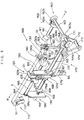
- this embodiment is characterized by 1) receiving a tape piece TT held by means of tape supporting members 140 between a tape clamp mechanism 120 of a tape piece supplying mechanism 100 and a tape end holding member 130 by air suction by means of a plate-like pressing part 451a, 452a of a pair of arms 451, 452 of a tape binding mechanism 200 as shown in Fig. 1A , 2) moving the tape piece to the predetermined position while holding it with arms 451, 452 and 3) lowering and separating the respective arms 451, 452 on the two sides respectively of the electric wire bundle W, as shown in Fig. 1B , to wind the tape piece TT around the electric wire bundle W.
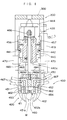
- Fig. 5 is a perspective view illustrating a schematic construction of the tape piece supplying mechanism 100.
- this tape piece supplying mechanism 100 includes 1) a tape drawing mechanism 110 for drawing the tape from a rotation roll 111 on which has been wound a tape having an adhesive surface on one side, 2) a tape clamping mechanism 200 for clamping the end of the tape T drawn from the rotation roll 111 and removing between the forward position (F-direction is called forward in Fig.
- a tape end holding member 130 for receiving and holding the end of the tape T from the tape clamping mechanism 120, held rockably on the base section BS and movable to the forward position
- a tape supporting member 140 which supports the tape T extended in a straight state between the tape end holding member 130 and the tape clamping mechanism 120 which have moved to a backward position from the lower direction
- a tape cutting member 150 for cutting the tape T at a position in the vicinity of the tape clamping mechanism 120 when in the backward position
- a driving mechanism 160 which drives in synchronization the clamping mechanism 120, the tape end holding member 130, the tape supporting member 140 and the tape cutting member 150.
- the tape drawing mechanism 110 includes 1) a supporting lever 112 mounted rockably to the base section BS thereto and centred at a predetermined position 112a in the vicinity of the lower end thereof, 2) an air cylinder 113 forming a driving means for inclining the supporting lever 112 backwards to draw the tape T by pushing the supporting lever 112 at its lower end 112c and 3) a photomicrosensor 114 provided on the rear portion of the supporting lever 112, as a tape ending checking means for detecting the tape T wound around the rotating roll 111 reaching the end.
- the center rear portion of the supporting lever 112 is provided with a sensor dog 115 for operating the photomicrosensor 114.
- the tape clamping mechanism 120 When the air cylinder 113 operates (see solid line in Fig. 6 ), the tape clamping mechanism 120 provided on the rear position thereof clamps and stops the end portion of the tape T. On the other hand, when the tape clamping mechanism 120 moves forward, the backwardly inclined supporting lever 112 is, along with this movement, stretched forward via the tape T in confrontation with its own weight, and raises itself until it erects approximately, as shown by the chain-dot line. Since the tape T has been drawn out of the rotating roll 111 before the tape clamping mechanism 120 moves forward for measuring, the tape clamping mechanism 120 does not confront a resistance in its forward movement.
- the tape clamping mechanism 120 moves forward, if the tape T on the rotating roll 111 has come to its roll end, the supporting lever 112 inclines backward by its own weight since it is not stretched forward, as shown in Fig. 6 . As a result, a photomicrosensor 114 is blocked by a sensor dog 115, so that the photomicrosensor 114 turns ON, thereby stopping the bundling device, and the replacement time of the rotating roll 111 is indicated via buzzers, etc.
- the tape clamping mechanism 120 includes 1) a plate member 121 having a lower end 121a which is mutually rotatable and moves forward/backward mounted to a third conveying axis 165 (to be described later) of the driving mechanism 160 and having an upper end 121b with a tape inserting hole 122 in angular section, and a clipping plate 123 provided vertically movably on the plate member 121 along its back surface, which clips the tape T at the upper position between itself and the rear side of the upper rim of the tape inserting hole 122, as shown in Fig. 7B .
- the clipping plate 123 permits the tape T to move through the tape inserting hole 122 in the lowered position shown in Fig. 7A.
- a cylindrical locking projection 124 which locks up with the locking hole 176a in the rocking lever 176 to be described later of the driving mechanism 160, is formed on the lateral side of the plate member 121.
- a cam follower 125 composed of a cylindrical projection following a tape clamping cam 168 of the driving mechanism 160 to be described later is formed at the lower portion of the clipping plate 123.
- the tape end holding member 130 is mounted rotatably to the base section BS around the rotation axis line at the central part thereof.
- the upper surface of one end of the tape end holding member 130 functions as a tape end holding member 130a for holding the end of the tape T with its adhesive force.
- the other end of the tape supporting member 130 is formed into a channel form containing a pair of projections 130b.
- the respective projections 130b are provided with an elongate hole section 131.
- a pin 183 formed on the end of the operation lever 182 contained in the tape end holding cam-link mechanism 180 to be described later of the driving mechanism 160 is inserted into the elongate hole section 131, respectively.
- the tape supporting member 140 comprises a rocking lever provided on the fourth conveying axis 195 of the driving mechanism 160 in an integrally rotatable way, a pair of rocking levers being provided with a predetermined distance therebetween (only one of them is shown in the drawing).
- the tape cutting member 150 comprises the plate member provided along the front surface of the plate member 121 of the tape clamping mechanism 120 in a vertically movable way and a cutter edge 150a formed on the upper surface.
- a cam follower 151 comprising a cylindrical projection following a tape cutting cam 167 to be described later of the driving mechanism 160 is formed.
- the tape cutting member 150 can be moved forward/backward together with the tape clamping mechanism 120.
- the tape cutting member 150 cuts the tape at the position along the front surface of the plate member 121 by the movement in the upper direction.
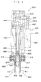
- the driving mechanism 160 includes 1) a motor M as a drive source, 2) a first conveying axle 161 driven by the motor M , 3) a second conveying axle 163 drive-joined via a first bevel gear mechanism 162 with the first conveying axle 161 and 4) the first bevel gear mechanism 162 and a third conveying axle 165 drive-joined via the second conveying axle 163 and the second bevel gear mechanism 164.
- the second conveying axle 163 is mounted in an integrally rotatable way with a reciprocating cam 163a for moving forwardly/backwardly the tape clamping mechanism 120 and the tape cutting member 150 via a reciprocating cam-link mechanism 170.
- the third conveying axle 165 is mounted in an integrally rotatable way with 1) a tape end holding cam 166 for rocking the tape end holding member 130 via the tape end holding cam-link mechanism 180, 2) a tape cutting cam 167 for vertically moving the tape cutting member 150 via the cam follower 151, 3) a tape clamping cam 168 for vertically moving the clipping plate 123 via the cam follower 125 and 4) a tape supporting cam 169 for rocking the tape supporting member 140 via a tape supporting cam-gear mechanism 190 between the supporting position and the non-supporting position.
- the reciprocating cam-link mechanism 170 includes 1) a cam follower 171 following the reciprocating cam 163a, 2) a rocking lever 172 having a base end supported rotatably with one end of an axis 173 and a tip end supporting the cam follower 171 rotatably, 3) a rocking lever 174 having one end supported integrally rotatable to the other end of the axis 173 and 4) an operation lever 182 having a lower end supported rotatable to the base section BS and an upper end formed with the locking hole 176a, which is coupled with the rocking lever 174 via a coupling lever 175.
- the tape end holding cam-link mechanism 180 includes a cam follower 181 following the tape holding cam 166 and the operation lever 182 supporting rotatably the cam follower 181 at the lower end.
- the pin 183 is formed protectively on the side surface opposing the upper end of the operation lever 182.
- the tape supporting cam-gear mechanism 190 includes
- This tape binding mechanism 200 includes 1) a frame 300 fixed to the moving holder 48 at the upper end thereof and 2) a winding mechanism 400 held to the frame 300.
- This winding mechanism 400 includes 1) a pair of electric wire bundle clamping mechanisms 410, 420 clamping electric wires at the time of tape winding to hold them, 2) an air cylinder 430 mounted to the frame 300 to provide a lifting means and 3) a lifting section 435 lifted by means of this air cylinder 430.
- the respective electric wire bundle clamping mechanisms 410, 412 include 1) a pair of clamping members 411, 412, 2) spur gears 413,414 connected rotatably to the respective clamping members 411, 412 and engaged with each other, 3) axial members 415, 416 fixing the respective spur gears at one end thereof and holding the respective spur gears 413, 414 rotatably to the frame 300, 4) a circular member 417 and a lever member 418 fixed to the other ends of these axial members 415, 416, respectively and 5) an air cylinder 419 holding a pin 418a formed on the tip end of the lever member 418 rotatably to the slit 419b at the lower end of a rod 419a.
- the air cylinder 419 and the axial members 415, 416 are, as shown in Figs. 11 and 12 , supported by means of the frame 300. Further, as shown in Figs. 10 , 12 and 13 , the pair of clamping members 411, 412 are provided with positioning surfaces 411a, 412a for positioning the upper end of the electric wire bundle W at a predetermined location when clamping the electric wire bundle W.
- the positioning surfaces 411a, 412a are, as shown in Fig. 10 , formed into a circular arc surface centering on the axial members 415, 416.
- Both upper ends of the air cylinder 419 of the respective electric wire bundle clamping mechanisms 410, 420 are connected together via a connecting rod 419c, as shown in Fig. 11 .
- the lifting section 435 includes 1) a lifting section body 440, 2) an elastic pressing mechanism 450 including the pair of arms 451, 452 held rockably relative to the lifting section body 440, for pressing resiliently the non-adhesive surface of the tape piece TT to wind it around the electric wire bundle W, 3) a tape piece holding mechanism 460 supported on the lifting section body 440 in a vertically movable way, for holding the tape piece TT on the lower surface of plate-like pressing sections 451a, 452a of the arms 451, 452 and 4) air cylinders 470 acting as a distance adjusting mechanism for adjusting the distances between clipping members 453, 454 formed on the tip portions of the arms 451, 452.
- the lifting section body 440 is designed to be slid vertically via a slide rail mechanism 480 provided between the body and the frame 300.
- the lifting section body 440 is connected to the air cylinder 430 via the tip end of the rod 430a of the air cylinder 430, connecting lever 443 and the connecting frame 444, and is made to move vertically together with the extension/retraction of the rod 430a of the air cylinder 430.
- the lifting section body 440 is, as shown in Fig. 8 , provided with rod inserting hole 440a through which a rod 465 to be described later of the tape piece holding mechanism 460 is inserted in a vertically movable way.
- the resilient pressing mechanism 450 includes 1) the pair of mutually opposing L-shaped and reverse-L shaped arms 451, 452 supported rockably relative to the lifting section body 440 around pins 441, 442, 2) the plate-like pressing sections 451a, 452a included in the respective arms 451, 452 and formed by leaf springs resiliently pressing the tape piece TT to the electric wire bundle W, 3) the clipping members 453, 454 formed at the mutually opposing free ends of the plate-like pressing sections 451a, 452a for embracing both ends of the tape piece TT at the lower side of the electric wire bundle W to clip them and 4) compression coil springs 456, 457 as a resilient spring-loading means acting in the direction for reducing the distance between these clipping members 453, 454.
- Holding surfaces 451c,452c for holding the tape piece are constituted by the lower surfaces of the plate-like pressing sections 451a, 452a, respectively.
- the base end sections (lower end section) of the respective clipping members 453, 454 are bent with a curvature radius opposite to that of the circumferential surface of the electric wire bundle W.
- the left arm 451 is spring-loaded in the counter-clockwise direction by means of the compression coil spring 456 and the right arm 452 is spring-loaded in the clockwise direction by means of the compression coil spring 457.
- Both clipping members 453, 454 are therefore spring-loaded in the direction to reduce the distance between the clipping members 453, 454, by means of the operation of the compression coil springs 456, 457. Further, both clipping members 453, 454 contact each other at a predetermined pressing force when no external force is applied.
- the tape piece holding mechanism 460 includes 1) a plurality of openings 461 formed respectively on the plate-like pressing sections 451a, 452a of the arms 451, 452 (see Fig. 1 ), 2), a flexible tube 462 whose lower part is connected to the respective openings 461, 3) a joint 463 provided with an air channel 463a connected to the upper ends of the respective flexible tubes 462, 4) a rod 465 having a lower end with the joint 463 fixed by a nut 464, which is supported on the lifting section body 440 in a vertically movable way by inserting the rod inserting hole 440a of the lifting section body 440 and 5) a nut 466 fixed to the upper end of this rod 465, which prevents the rod 465 from coming out.
- the openings 461 are connected with an air suction pump (not shown) via the air channel 463a and a hose 466. By sucking air through the openings 461, the tape piece can be held in a stretched state relative to the plate-like pressing sections 451a, 452a of the arms 451, 452.
- the air cylinders 470 acting as a distance adjusting mechanism are mounted roughly at the center portion in the height direction of the respective arms 451, 452.
- the respective air cylinders 470 are effective to widen the distance between both clipping members 453, 454 by extending the respective air cylinder piston rods to engage with the side surfaces of the lifting section body 440.
- the tape binding mechanism 200 is located at a home position upstream of the tape piece supplying mechanism 110 and, at a position downstream of this tape binding mechanism 200, the tape piece supplying mechanism 110 cuts the tape into tape pieces TT of the predetermined length according to the operations shown in Figs. 14 to 18 to make them deliverable to arms 451, 452 of the tape binding mechanism 200.
- the tape clamping mechanism 120 clamps the end of the tape T.
- the tape clamping mechanism 120 is moved forward and, at the same time, the tape end holding member 130 is inserted into the tape inserting hole 122 and is raised to the horizontal state.
- the raised tape end holding member 130 presses the ends of the tape T against the upper surface through the tape inserting hole 122, thereby adhering the adhesive surface of the tape T onto the tape end holding section 130a on the upper surface thereof.
- the tape clamping mechanism 120 moves backward in a predetermined stroke while unclamping the tape T (see Fig. 16 ) and clamps the tape T again at the location where it has moved backward, as shown in Fig. 17 .
- a pair of tape supporting members 140 are moved circularly to the horizontal state to hold the lower surface of the tape T.
- the arms 451,452 are lowered by the air cylinder 430 and, as shown in Fig. 18 , contacts the non-adhesive surface of the tape T and holds it by suction. Then, the tape end holding member 130 is inclined downward to release the holding of the end of the tape T. Simultaneously, the tape cutting member 150 is raised along with the side surface of the plate member 121 of the tape clamping mechanism 120 to cut the tape T. Since the tape supporting members 140 hold the tape piece TT in the stretched state, the plate-like pressing sections 451a, 452a of the arms 451, 452 can receive the tape piece TT in the stretched state.
- the arms 451, 452 which have received the tape piece TT are raised by the air cylinder 430. Then, by means of the movement of the respective moving holders 44, 46 in the X- and Y-directions, they are moved to the upstream of a predetermined position on the wire lay-out board 9 where the tape will be wound and is directed in the required direction suitable for the direction of the electric wire bundle W by means of the rotation driving mechanism. Thereafter, the tape binding mechanism 200 is lowered by the movement of the Z- direction moving body, so that the bundling operation becomes ready. At this point, the electric wire bundle W is arranged between the clamping members 411, 412 of the electric wire bundle clamping mechanism 460 of the tape binding mechanism 200.
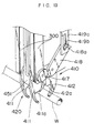
- a pair of electric wire bundle clamping mechanisms 460 collect the electric wire bundle W into approximately circular form in section by extending the air cylinder 419, using the clamping members 411, 412 to clamp them. Since a pair of the electric wire bundle clamping mechanisms 460 clips the portion of the electric wire bundle W where the tape piece TT will be wound and clamps a pair of locations at a predetermined distance apart respectively, the section of the electric wire bundle W located between the two clamping mechanisms 460 is held firmly in, a state having a roughly circular form in section. Accordingly, it is possible to wind the tape piece TT at the predetermined position of the electric wire bundle W, precisely and without sagging. Incidentally, in Fig. 19, the arms 451, 452 are not shown.
- the clipping sections 453, 454 at the end of the plate-like pressing sections 451a, 452a clip the tip ends TT1 of both tape pieces TT as if to embrace them, as shown in Fig; 20B, and lower themselves while laminating the tip ends together at the underside of the electric wire bundle W.
- the tape binding mechanism 200 including the arms 451, 452 returns to the home position upstream of the tape piece supplying mechanism 100 and, while the tape binding mechanism 200 is performing the winding operations, the tape piece supplying mechanism 100 simultaneously operates and the deliverable tape piece TT has already been prepared. Therefore, in the next bundling operation, as soon as the tape binding mechanism 200 returns to the home position, the operation to lower the arms 451, 452 to receive the tape piece TT (see Fig. 17 ) can be started. This is because the tape supplying step for cutting and supplying the tape piece TT and the tape winding step for winding the tape piece TT around the electric wire bundle W can be conducted simultaneously by separately arranging the tape piece supplying mechanism 100 and the tape binding mechanism 200. Accordingly, the bundling operation can be conducted efficiently.
- the arms 451,452 holding the tape piece TT are lowered from a position above the electric wire bundle W, around the two opposite sides thereof to wind the tape piece TT around the electric wire bundle W, the winding can be conducted in a very narrow space in comparison with a conventional device wherein the bobbin is rotated. As a result, it becomes possible to tape the key portion of the electric wire bundle W laid out on the wire lay-out board 9, automatically.
- the arms 451, 452 resiliently press the tape piece TT around the electric wire bundle W by means of the plate-like pressing sections 451a, 452a formed by a leaf spring, the tape piece TT can be wound tightly around the electric wire bundle W, so that precise and tight bundling can be performed.
- the clipping members 453, 454 for laminating both ends of the tape piece TT to each other are formed on the free ends of the plate-like pressing sections 451a, 452a, it is possible to transfer smoothly from the operation of pressing the tape piece TT onto the electric wire bundle W to the operation of clipping the end of the tape piece TT below the electric wire bundle W. Accordingly, the tape piece TT can be wound tightly around the electric wire bundle W, so that more precise bundling can be conducted.
- the diameter of the electric wire bundle can be decreased by the tape piece TT as the pair of clipping sections 453, 454 are lowered in the state where both ends of the tape piece TT are clipped by embracing them below the electric wire bundle W, more precise bundling can be conducted
- the clipping members 453, 454 can be slid into the lower side of the electric wire bundle W without requiring a large space. Therefore, the tape winding can be conducted in a smaller space. Also, since the plate-like pressing sections 451a, 452a formed by leaf springs have a reverse curvature against the curvature of the circular surface of the electric wire bundle W, both clipping members 453, 454 can be rapidly slid to the lower side of the electric wire bundle W by making use of this repulsion force. As a result, the end portions TT1 of the tape piece TT can be clipped to each other without sagging. Therefore, still more precise bundling can be conducted.
Landscapes
- Engineering & Computer Science (AREA)
- Mechanical Engineering (AREA)
- Basic Packing Technique (AREA)
- Adhesive Tape Dispensing Devices (AREA)
Claims (14)
- Dispositif de ligature au moyen d'une bande adhésive pour lier un faisceau de câbles électriques avec une pièce de bande adhésive ayant une surface adhésive d'un côté, comprenant :un corps de dispositif (300) ;une paire de bras (451, 452) disposés de manière à être verticalement mobiles par rapport audit corps de dispositif (300), et ayant des extrémités libres pouvant être mises mutuellement en contact ou séparées (453, 454), respectivement ;une surface de maintien respective (451c, 452c) formée sur chacun desdits bras (451, 452) de manière à être continue avec lesdites extrémités libres (453, 454) pour maintenir ladite pièce de bande adhésive ;des moyens de ressort (456, 457) destinés à solliciter lesdites extrémités libres (453, 454) desdits bras pour les mettre au contact l'une de l'autre ;des moyens de maintien de pièce de bande adhésive (100) destinés à maintenir ladite pièce de bande adhésive avec une force de maintien prédéterminée tout en mettant la surface non adhésive de ladite pièce de bande adhésive en contact avec lesdites surfaces de maintien (451c, 452c) desdits bras (451, 452) ; etdes moyens de déplacement de bras (430) destinés à déplacer lesdits bras (451, 452) verticalement par rapport audit corps de dispositif (300).
- Dispositif de ligature au moyen d'une bande adhésive selon la revendication 1, dans lequel un premier bras (451) de ladite paire de bras (451, 452) est en forme de L tandis que l'autre bras (452) est en forme de L renversé, symétrique audit premier bras de ladite paire de bras ;les bras respectifs (451, 452) ont une première partie (451b, 452b) et une deuxième partie (451a, 452a) qui est continue avec une extrémité inférieure de ladite première partie ; et
ladite surface de maintien comprend une surface inférieure (451c, 452c) de ladite deuxième partie et ladite extrémité libre est comprise dans ladite deuxième partie. - Dispositif de ligature au moyen d'une bande adhésive selon la revendication 2, dans lequel ladite première partie (451b, 452b) comprend un élément élastique et agit également comme lesdits moyens de ressort.
- Dispositif de ligature au moyen d'une bande adhésive selon la revendication 2 ou 3, dans lequel ladite deuxième partie (451a, 452a) comprend un ressort à lames et comprend ladite extrémité libre et ladite surface de maintien.
- Dispositif de ligature au moyen d'une bande adhésive selon la revendication 3, dans lequel ladite deuxième partie (451a, 452a) est formée avec une ouverture (461) sur ladite surface de maintien ; et
lesdits moyens destinés à maintenir ladite pièce de bande adhésive comprennent des moyens d'aspiration d'air destinés à aspirer de l'air à travers ladite ouverture (461). - Dispositif de ligature au moyen d'une bande adhésive selon la revendication 1, comprenant en outre des moyens (470) destinés à séparer ladite paire de bras contre lesdits moyens de ressort (456, 457).
- Dispositif de ligature au moyen d'une bande adhésive selon la revendication 1, dans lequel chacune desdites surfaces de maintien (451c, 452c) est pourvue d'une ouverture (461) et lesdits moyens destinés à maintenir ladite pièce de bande adhésive comprennent des moyens d'aspiration d'air destinés à aspirer de l'air à travers ladite ouverture (461).
- Dispositif de ligature au moyen d'une bande adhésive selon la revendication 1, dans lequel lesdits moyens de ressort comprennent des ressorts de tension (456, 457) intercalés entre lesdits bras de la paire de bras (451, 452).
- Dispositif de ligature au moyen d'une bande adhésive selon l'une quelconque des revendications 1 à 8, comprenant en outre une paire de moyens de serrage de faisceau de câbles électriques (411, 412), prévus sur ledit corps de dispositif (300), afin de rassembler une paire de parties mutuellement séparées d'une distance prédéterminée d'une partie dudit faisceau de câbles électriques destinés à être entourés de ladite pièce de bande adhésive en une section ayant une forme globalement circulaire, de manière à serrer ladite paire de parties, respectivement.
- Dispositif de ligature au moyen d'une bande adhésive selon la revendication 1, comprenant en outre des moyens de coupe de bande adhésive (150) destinés à couper une bande adhésive déroulée d'un rouleau de ladite bande adhésive ; etdes moyens (140) destinés à maintenir ladite pièce de bande adhésive coupée avec lesdits moyens de coupe de bande adhésive dans un état où elle peut être distribuée auxdites surfaces de maintien (451c, 452c) desdits bras (451, 452).
- Dispositif de ligature au moyen d'une bande adhésive selon la revendication 10, comprenant en outre des moyens de déplacement de corps de dispositif afin de déplacer ledit corps de dispositif ;dans lequel lesdits moyens de déplacement de corps de dispositif (45) se déplacent entre une position supérieure de ladite pièce de bande adhésive maintenue par lesdits moyens de maintien de ladite pièce de bande adhésive dans ledit état de distribution, et une position au-dessus d'un emplacement dudit faisceau de câbles électriques implantés sur une carte d'implantation de câbles électriques destinés à être liés avec ladite pièce de bande adhésive.
- Dispositif de ligature au moyen d'une bande adhésive selon la revendication 1, comprenant en outre des moyens (45) pour déplacer ledit corps de dispositif à une position au-dessus d'un emplacement auquel ledit faisceau de câbles électriques implantés sur une carte d'implantation de câbles électriques doit être lié.
- Procédé de ligature au moyen d'une bande adhésive pour lier un faisceau de câbles électriques au moyen d'une pièce de bande adhésive ayant une surface adhésive d'un côté, comprenant le fait de :maintenir la pièce de bande adhésive sur des surfaces de maintien respectives (451c, 452c) qui sont prolongées par des extrémités libres (453, 454) d'une paire de bras (451, 452) de manière à ce que la surface adhésive soit orientée vers le bas ; etabaisser les extrémités libres (453, 454) des bras (451, 452) sur les deux côtés séparés par une partie supérieure du faisceau de câbles électriques ;dans lequel l'action d'abaisser les extrémités libres (453, 454) comprend l'étape consistant à couvrir la pièce de bande adhésive autour du faisceau de câbles électriques tout en pressant la pièce de bande adhésive sur le faisceau de câbles électriques par lesdites extrémités libres (453, 454) pendant l'abaissement initial, et à serrer les deux extrémités de la pièce de bande adhésive dans un état où les surfaces adhésives auxdites deux extrémités de la pièce de bande adhésive sont collées l'une à l'autre sous le faisceau de câbles électriques au moyen desdites extrémités libres (453, 454) pendant la poursuite de l'abaissement, de manière à stratifier les surfaces adhésives l'une à l'autre.
- Procédé de ligature au moyen d'une bande adhésive selon la revendication 13, comprenant en outre le fait de couper une bande adhésive déroulée d'un rouleau de la bande adhésive ; et de distribuer la pièce de bande adhésive obtenue à l'étape de coupe sur les surfaces de maintien des deux bras.
Applications Claiming Priority (2)
| Application Number | Priority Date | Filing Date | Title |
|---|---|---|---|
| JP5305570A JP2820878B2 (ja) | 1993-12-06 | 1993-12-06 | 電線束へのテープ巻付け装置及びその方法並びに電線束へのテープ結束装置 |
| JP305570/93 | 1993-12-06 |
Publications (2)
| Publication Number | Publication Date |
|---|---|
| EP0657355A1 EP0657355A1 (fr) | 1995-06-14 |
| EP0657355B1 true EP0657355B1 (fr) | 1998-03-04 |
Family
ID=17946742
Family Applications (1)
| Application Number | Title | Priority Date | Filing Date |
|---|---|---|---|
| EP94309078A Expired - Lifetime EP0657355B1 (fr) | 1993-12-06 | 1994-12-06 | Procédé et dispositif pour ligaturer un faisceau de câbles électriques au moyen d'une bande adhésive |
Country Status (4)
| Country | Link |
|---|---|
| US (1) | US5614042A (fr) |
| EP (1) | EP0657355B1 (fr) |
| JP (1) | JP2820878B2 (fr) |
| DE (1) | DE69408799T2 (fr) |
Cited By (2)
| Publication number | Priority date | Publication date | Assignee | Title |
|---|---|---|---|---|
| CN109335064A (zh) * | 2018-11-14 | 2019-02-15 | 盐城市华悦汽车部件有限公司 | 一种挂排式汽车线束自动捆扎贴标设备 |
| CN112319891A (zh) * | 2020-10-30 | 2021-02-05 | 四川九洲电器集团有限责任公司 | 一种扎带机及扎带方法 |
Families Citing this family (25)
| Publication number | Priority date | Publication date | Assignee | Title |
|---|---|---|---|---|
| JP3713108B2 (ja) * | 1996-08-14 | 2005-11-02 | 富士写真フイルム株式会社 | ピロータイプ包装装置 |
| JP2000011778A (ja) * | 1998-06-22 | 2000-01-14 | Sumitomo Wiring Syst Ltd | ワイヤハーネス用電線の切断寸法設定方法 |
| US6202387B1 (en) * | 1998-11-09 | 2001-03-20 | Reginald M. Mudd | Apparatus and method for banding wrapped silverware |
| JP2001250734A (ja) * | 1999-12-28 | 2001-09-14 | Tanaka Seiki Kk | テーピング装置及びテーピング方法 |
| US6968779B2 (en) | 2000-03-15 | 2005-11-29 | Enterprises International, Inc. | Apparatus and methods for wire-tying bundles of objects |
| EP1611012B1 (fr) * | 2003-04-08 | 2007-02-14 | Wella Aktiengesellschaft | Dispositif et procede pour lier, envelopper ou marquer automatiquement des objets |
| JP2012115021A (ja) * | 2010-11-24 | 2012-06-14 | Yazaki Corp | ワイヤハーネス配索構造 |
| CN102501998A (zh) * | 2011-11-08 | 2012-06-20 | 建科机械(天津)股份有限公司 | 捆扎钢筋用的自动聚拢装置 |
| CA150789S (en) * | 2012-10-24 | 2014-02-26 | Desarrollos Especiales De Sist S De Anclaje S A | Agricultural tape binder |
| JP6315808B2 (ja) * | 2014-08-08 | 2018-04-25 | 日特エンジニアリング株式会社 | コイル製造装置 |
| CH711364A2 (de) * | 2015-07-30 | 2017-01-31 | Signode Ind Group Llc | Halteeinrichtung mit integrierter Ladestation für eine Umreifungsvorrichtung. |
| CN105836196B (zh) * | 2016-04-19 | 2017-06-20 | 杭州鼎巅科技有限公司 | 一种线束包胶机的自动送料机构及使用方法 |
| CN105775201B (zh) * | 2016-04-28 | 2018-05-11 | 天津市福鼎机电设备有限公司 | 一种基于从动开合夹块装置的钢筋打捆机 |
| JP6626864B2 (ja) * | 2017-07-31 | 2019-12-25 | 矢崎総業株式会社 | テープ巻付装置 |
| JP2019081550A (ja) * | 2017-10-27 | 2019-05-30 | 株式会社Fdkエンジニアリング | 物品の結束装置及び結束方法 |
| CN109677992B (zh) * | 2018-12-21 | 2023-11-17 | 中国信息通信研究院 | 一种用于串音测试的样品制作系统 |
| CN109515806A (zh) * | 2019-01-16 | 2019-03-26 | 深圳市诺峰光电设备有限公司 | 一种玻璃叠片自动捆带包覆装置及其捆带包覆工艺 |
| CN109533442A (zh) * | 2019-01-16 | 2019-03-29 | 深圳市诺峰光电设备有限公司 | 一种自动捆带装盒机及其捆带装盒工艺 |
| DE102019213325A1 (de) | 2019-09-03 | 2021-03-04 | Leoni Bordnetz-Systeme Gmbh | Montagekopf sowie Verfahren zur automatisierten Umwicklung eines Leitungsstrangs |
| CN111532510B (zh) * | 2020-04-24 | 2021-11-12 | 徐州陵盛新能源有限公司 | 一种稳定型瓦楞纸箱连续包装装置 |
| CN113264218B (zh) * | 2021-05-12 | 2022-08-26 | 安徽国稷建设集团有限公司 | 一种建筑管材捆扎设备及捆扎方法 |
| CN114426114A (zh) * | 2022-03-07 | 2022-05-03 | 隆士丹智能科技(苏州)有限公司 | 一种贴胶带机构 |
| CN114955063B (zh) * | 2022-07-08 | 2023-09-22 | 福建省迈为智能装备有限公司 | 一种竹条自动扎捆设备以及方法 |
| CN119456877A (zh) * | 2025-01-17 | 2025-02-18 | 福建安通电装有限公司 | 一种汽车轻量化线束截断装置 |
| CN119840895B (zh) * | 2025-03-21 | 2025-07-29 | 吉希电子(上海)有限公司 | 一种电子连接线生产用自动捆扎机 |
Family Cites Families (12)
| Publication number | Priority date | Publication date | Assignee | Title |
|---|---|---|---|---|
| US1991281A (en) * | 1932-06-17 | 1935-02-12 | Gerh Arehns Mek Verkst Ab | Apparatus for banding boxes |
| US2873564A (en) * | 1957-09-09 | 1959-02-17 | Bernard E Bogeskov | Method for wrapping an object with adhesive tape |
| US3092016A (en) * | 1959-02-19 | 1963-06-04 | Societes Aries La Bougie B G & | Wire tying machine |
| US3535189A (en) * | 1967-02-17 | 1970-10-20 | Johnson & Johnson | Pressure-sensitive adhesive tape applicator |
| US3627300A (en) * | 1970-03-19 | 1971-12-14 | Panduit | Wire cable harness assembly apparatus |
| EP0039188A1 (fr) * | 1980-04-29 | 1981-11-04 | Lansing Bagnall Limited | Appareil applicateur à fonctionnement pneumatique et procédé pour appliquer une bande adhésive |
| JPS5912052A (ja) * | 1982-07-09 | 1984-01-21 | Hitachi Ltd | テ−プ巻付装置 |
| JPS5964477A (ja) * | 1982-09-30 | 1984-04-12 | Toshiba Corp | テ−ピングマシン |
| JPS5990377A (ja) * | 1982-11-12 | 1984-05-24 | 住友電気工業株式会社 | 枝電線自動接続装置 |
| JPS60163307A (ja) * | 1984-02-03 | 1985-08-26 | 古河電気工業株式会社 | ハ−ネス組立用束縛機 |
| IT1241222B (it) * | 1990-05-09 | 1993-12-29 | Irico S P A | Macchina automatica per la nastratura ed il taglio di fasci di fibre |
| US5063803A (en) * | 1990-07-31 | 1991-11-12 | A. J. Panneri Enterprises, Inc. | Tape cutting and dispensing machine |
-
1993
- 1993-12-06 JP JP5305570A patent/JP2820878B2/ja not_active Expired - Lifetime
-
1994
- 1994-12-02 US US08/352,219 patent/US5614042A/en not_active Expired - Fee Related
- 1994-12-06 DE DE69408799T patent/DE69408799T2/de not_active Expired - Fee Related
- 1994-12-06 EP EP94309078A patent/EP0657355B1/fr not_active Expired - Lifetime
Cited By (2)
| Publication number | Priority date | Publication date | Assignee | Title |
|---|---|---|---|---|
| CN109335064A (zh) * | 2018-11-14 | 2019-02-15 | 盐城市华悦汽车部件有限公司 | 一种挂排式汽车线束自动捆扎贴标设备 |
| CN112319891A (zh) * | 2020-10-30 | 2021-02-05 | 四川九洲电器集团有限责任公司 | 一种扎带机及扎带方法 |
Also Published As
| Publication number | Publication date |
|---|---|
| JPH07157176A (ja) | 1995-06-20 |
| EP0657355A1 (fr) | 1995-06-14 |
| US5614042A (en) | 1997-03-25 |
| DE69408799T2 (de) | 1998-06-18 |
| DE69408799D1 (de) | 1998-04-09 |
| JP2820878B2 (ja) | 1998-11-05 |
Similar Documents
| Publication | Publication Date | Title |
|---|---|---|
| EP0657355B1 (fr) | Procédé et dispositif pour ligaturer un faisceau de câbles électriques au moyen d'une bande adhésive | |
| US6640425B1 (en) | Apparatus for producing wire harnesses for automotive vehicles | |
| EP0763879B1 (fr) | Appareil et procédé de bobinage du conducteur d'un stator | |
| US4593452A (en) | Robotic harness maker | |
| US5230147A (en) | Electrical hardness termination apparatus and method | |
| JP2982600B2 (ja) | ワイヤーハーネスの仮結束回路の製造方法および装置 | |
| US4685636A (en) | Reel and reel handling system | |
| GB2111322A (en) | Method of processing end portions of covered wires in a wire harness | |
| JP7359811B2 (ja) | ワイヤハーネス製造装置 | |
| JPH0664949B2 (ja) | ハーネス製造装置 | |
| EP3261202B1 (fr) | Système et procédé de traitement de faisceaux de fils | |
| CN114365239A (zh) | 用于自动地缠绕缆线股的组装头以及方法 | |
| JPH09501258A (ja) | 分岐構造を有するハーネスを製造する方法および装置 | |
| JP3703503B2 (ja) | ケーブル処理機械のためのケーブルを束ねる装置 | |
| JPH0614476B2 (ja) | ターミナルストリップ巻き戻し装置 | |
| US4977934A (en) | Multiple wire straightener module for an automated cable assembly system | |
| US6353993B1 (en) | Cable finishing and resistance testing machine | |
| JP3077546B2 (ja) | 電線束組立体の取り入れ装置 | |
| JP3013657B2 (ja) | 電線受渡し機構及びこれを含んだ電線受渡し装置 | |
| JP2716913B2 (ja) | 電線結束用テープ巻付け装置 | |
| JP3200146B2 (ja) | ハーネス製造装置 | |
| JP3077545B2 (ja) | 電線束組立体のテーピング装置およびそれを用いたテーピング方法 | |
| JPH04229910A (ja) | リード線製造装置及びそれに使用するワイヤ把持装置 | |
| JPH10507300A (ja) | 電気ハーネスを製造する装置及び方法 | |
| JP2888707B2 (ja) | 端子挿入ガイド装置 |
Legal Events
| Date | Code | Title | Description |
|---|---|---|---|
| PUAI | Public reference made under article 153(3) epc to a published international application that has entered the european phase |
Free format text: ORIGINAL CODE: 0009012 |
|
| AK | Designated contracting states |
Kind code of ref document: A1 Designated state(s): DE FR GB |
|
| 17P | Request for examination filed |
Effective date: 19950721 |
|
| 17Q | First examination report despatched |
Effective date: 19960903 |
|
| GRAG | Despatch of communication of intention to grant |
Free format text: ORIGINAL CODE: EPIDOS AGRA |
|
| GRAG | Despatch of communication of intention to grant |
Free format text: ORIGINAL CODE: EPIDOS AGRA |
|
| GRAH | Despatch of communication of intention to grant a patent |
Free format text: ORIGINAL CODE: EPIDOS IGRA |
|
| GRAH | Despatch of communication of intention to grant a patent |
Free format text: ORIGINAL CODE: EPIDOS IGRA |
|
| GRAA | (expected) grant |
Free format text: ORIGINAL CODE: 0009210 |
|
| AK | Designated contracting states |
Kind code of ref document: B1 Designated state(s): DE FR GB |
|
| REF | Corresponds to: |
Ref document number: 69408799 Country of ref document: DE Date of ref document: 19980409 |
|
| ET | Fr: translation filed | ||
| PLBE | No opposition filed within time limit |
Free format text: ORIGINAL CODE: 0009261 |
|
| STAA | Information on the status of an ep patent application or granted ep patent |
Free format text: STATUS: NO OPPOSITION FILED WITHIN TIME LIMIT |
|
| 26N | No opposition filed | ||
| PGFP | Annual fee paid to national office [announced via postgrant information from national office to epo] |
Ref country code: DE Payment date: 20001129 Year of fee payment: 7 |
|
| PGFP | Annual fee paid to national office [announced via postgrant information from national office to epo] |
Ref country code: GB Payment date: 20001206 Year of fee payment: 7 |
|
| PGFP | Annual fee paid to national office [announced via postgrant information from national office to epo] |
Ref country code: FR Payment date: 20001212 Year of fee payment: 7 |
|
| PG25 | Lapsed in a contracting state [announced via postgrant information from national office to epo] |
Ref country code: GB Free format text: LAPSE BECAUSE OF NON-PAYMENT OF DUE FEES Effective date: 20011206 |
|
| REG | Reference to a national code |
Ref country code: GB Ref legal event code: IF02 |
|
| PG25 | Lapsed in a contracting state [announced via postgrant information from national office to epo] |
Ref country code: DE Free format text: LAPSE BECAUSE OF NON-PAYMENT OF DUE FEES Effective date: 20020702 |
|
| GBPC | Gb: european patent ceased through non-payment of renewal fee |
Effective date: 20011206 |
|
| PG25 | Lapsed in a contracting state [announced via postgrant information from national office to epo] |
Ref country code: FR Free format text: LAPSE BECAUSE OF NON-PAYMENT OF DUE FEES Effective date: 20020830 |
|
| REG | Reference to a national code |
Ref country code: FR Ref legal event code: ST |