EP0657580A2 - Section de séchage d'une machine à papier - Google Patents
Section de séchage d'une machine à papier Download PDFInfo
- Publication number
- EP0657580A2 EP0657580A2 EP94119391A EP94119391A EP0657580A2 EP 0657580 A2 EP0657580 A2 EP 0657580A2 EP 94119391 A EP94119391 A EP 94119391A EP 94119391 A EP94119391 A EP 94119391A EP 0657580 A2 EP0657580 A2 EP 0657580A2
- Authority
- EP
- European Patent Office
- Prior art keywords
- drying
- group
- cylinders
- drying cylinders
- dryer
- Prior art date
- Legal status (The legal status is an assumption and is not a legal conclusion. Google has not performed a legal analysis and makes no representation as to the accuracy of the status listed.)
- Granted
Links
Images
Classifications
-
- D—TEXTILES; PAPER
- D21—PAPER-MAKING; PRODUCTION OF CELLULOSE
- D21F—PAPER-MAKING MACHINES; METHODS OF PRODUCING PAPER THEREON
- D21F5/00—Dryer section of machines for making continuous webs of paper
- D21F5/02—Drying on cylinders
- D21F5/022—Heating the cylinders
- D21F5/028—Heating the cylinders using steam
-
- D—TEXTILES; PAPER
- D21—PAPER-MAKING; PRODUCTION OF CELLULOSE
- D21F—PAPER-MAKING MACHINES; METHODS OF PRODUCING PAPER THEREON
- D21F5/00—Dryer section of machines for making continuous webs of paper
- D21F5/02—Drying on cylinders
- D21F5/04—Drying on cylinders on two or more drying cylinders
Definitions
- the present invention relates to a dryer section of a paper machine, and in particular to the vapor pressure profile of the dryer cylinders of the dryer section.
- the paper web is formed from a very wet fibrous suspension, which first reaches a wire section via a headbox, in which part of the water is removed. It is then further dewatered in a press section before being fed to a dryer section.
- a dryer section of a paper machine typically comprises a number of hollow metal drying cylinders or dryers, to which pressurized steam is supplied to heat the peripheral surfaces of the cylinders.
- the paper to be dried is guided on a path that sequentially brings it into contact with the peripheral surface of each drying cylinder.
- the heat supplied to the paper web by means of the drying cylinders heats the paper web and in this way promotes the evaporation of the water from the paper web.
- the paper web can be reached.
- the paper web when entering the dryer section, the paper web has a dry content of 45% and leaves the dryer section with a dry content of approximately 92% to 98%.
- the amount of heat supplied to the paper web as it passes each drying cylinder is a function of the temperature of the peripheral surface of the corresponding drying cylinder.
- the temperature is a function of the steam pressure in the drying cylinder. For example, a drying cylinder with a higher steam pressure is hotter than a drying cylinder with a lower steam pressure.
- All drying cylinders in a dryer section are fed with steam, which comes, for example, from a common steam source.
- the pressure prevailing in the different drying cylinders is set to different values, so that different drying cylinder temperatures are present.
- the steam pressure can be controlled in that the amount of steam supplied to the drying cylinders can be adjusted by means of valves. If the paper web becomes increasingly dry, different cylinder temperatures lead to an optimally dried paper web.
- a drying section comprises a number of drying cylinders, which are usually operated in several separate drying cylinder groups.
- the dryer groups are usually designed as single-row or double-row dryer groups.
- the actively heated drying cylinders are grouped in two rows.
- the paper web passes through the two-row group in such a way that one side of the paper web first comes into contact with a drying cylinder of one row and the other side of the paper web subsequently with a drying cylinder of the other row. This process is then repeated until the end of the two-row drying group, the paper web thus describing a meandering or zigzag path, with the paper web rotating around the drying cylinders one after the other.
- a web guide roller or deflection roller is provided, which is preferably designed as a suction roller and lies between adjacent drying cylinders in the dryer group.
- the guide roll is placed so that the paper web wraps around a substantial portion of the circumference of adjacent drying cylinders in the single row dryer group.
- each single-tier dryer group there is a belt supporting the paper web, namely a dry felt belt (hereinafter referred to only as dry felt) intended.
- dry felt belt hereinafter referred to only as dry felt
- dryer fabric belts can also be used, only dry felt belts being referred to below.
- the dry felt supports a surface of the paper web and transports it from one drying cylinder to the next within a single-row drying group.
- the path of the paper web from one drying cylinder in one row to the drying cylinder in the next row is not supported by a drying felt.
- Such lines that are not supported by a dry felt are called free trains.
- the dried paper web is subjected to a further subsequent post-treatment, for example a surface treatment in a coating press or an on-line coating machine.
- a further subsequent post-treatment for example a surface treatment in a coating press or an on-line coating machine.
- Efforts have been made to control or regulate the temperature of the paper web at the end of the dryer section in the last section of the dryer section, in particular in the double-row dryer groups of the hybrid arrangement, in such a way that optimum paper web production is achieved.
- the present invention relates to a heat control control for a dryer section, which is achieved by control / regulation (hereinafter referred to as control for reasons of simplicity) of supplying steam to at least some drying cylinders.
- the object of the present invention is to produce a paper web with optimal quality, with the highest possible running efficiency (runnability).
- Another object of the present invention is to provide the paper web with a certain surface temperature that is as reduced as possible subsequent paper web post-treatment in the paper machine.
- Yet another object of the present invention is to optimize paper web manufacture in such a hybrid dryer section by reducing the vapor pressure in at least some of the dryer cylinders compared to the other dryer cylinders.
- the present invention relates to a hybrid dryer section of at least one, preferably a few, single-row dryer groups, which are followed by at least one double-row dryer group at the end of the dryer section.
- a not inconsiderable part of the heating and drying of the paper web is achieved in the single-row dryer group (s), the final drying being carried out in the double-row dryer group.
- the first or upstream number of drying cylinders with a in a two-row dryer group preferably in the last two-row dryer group of the dryer section operated high steam pressure, while the second or downstream number of drying cylinders are operated with a low steam pressure. Accordingly, the temperatures of the second number of drying cylinders are reduced in accordance with the decrease in the vapor pressure.
- a last two-row dryer group is preferably divided between the upstream and the downstream number of drying cylinders.
- the present invention is not limited to the use of only a single two-tier dryer group. It is also possible for the two-row arrangement to be present in two drying groups. In each two-row dryer group, an upper endless drying felt is assigned to the upper row of drying cylinders, while a lower endless drying felt is assigned to the lower row of drying cylinders. This dry felt arrangement is known. If the double-row section of the dryer section has more than one dryer group, an upper and a lower dryer felt are assigned to each group.
- the present invention relates to a last, downstream number of drying cylinders of a two-row section of a drying section, the drying cylinders operating with a lower vapor pressure than the previous upstream number of drying cylinders of the two-row section. This allows the surface temperature of the downstream number of drying cylinders to be reduced. In this way the temperature of the paper web is brought to a level that allows further post-treatment very well.
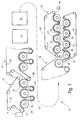
- FIG. 1 shows a dryer section 10 of a paper machine, to which a wet paper web is fed from a press section 11.
- the paper web 30 passes through five successive single-row drying groups 12, 13, 14, 15 and 16, which first heat the paper web 30 during the passage and then dry it.
- the individual drying groups are constructed essentially in the same way, so that some of them are shown schematically in FIG. 1 as boxes.
- drying group 12 This comprises a single row of drying cylinders 20, the individual drying cylinders alternating with respective suction and deflection rollers 22.
- An endless one Drying felt 24 passes through the drying group 12 in a zigzag pattern over the suction roller 22, over the drying cylinder 20, then again over a suction roller 22 and a drying cylinder, etc.
- the drying felt 24 is by means of the dry felt roller 23 deflected and led back to the beginning of the drying group. Further dry felt rolls are arranged along the return path of the dry felt for guidance.
- the paper web 30 is guided on the one hand over the suction rollers 22 as it passes through the drying group such that the dry felt lies between the paper web 30 and the suction roller 22.
- the paper web 30 is then passed over the drying cylinder 20 such that the paper web 30 lies between the drying felt and drying cylinder and comes into direct contact with the drying cylinder 20.
- the drying felt 24 presses the underside of the paper web securely against the drying cylinder, which heats the paper web 30, so that the moisture evaporates therefrom when the paper web leaves the drying cylinder 20.
- the transfer of the paper web 30 from one dryer group 12 to the next dryer group 13, in which the drying process described above is continued, is possible in many ways, the detailed description being dispensed with.
- the transfer takes place between the single-tier dryer groups a paper web takeover by means of vacuum, the paper web running around the last cylinder 20 in group 12, then running onto a dry felt 25 of the next group 13 on the first suction roll 26 of this group 13.
- the single-row dryer groups 12 to 16 shown contain a total of 22 drying cylinders.
- a two-row dryer group 40 is provided, which has an upper row of drying cylinders 42 and a lower row of drying cylinders 44.
- the paper web 30 passes through the two-row drying group in a zigzag shape between the drying cylinders 44 of the lower row and the drying cylinders 42 of the upper row, with adjacent drying cylinders lying in different rows in the transport direction.
- the top of the paper web 30 comes into direct contact with the drying cylinders 44 of the lower row and the underside of the paper web comes into direct contact with the drying cylinders 42 of the upper row.
- This two-row dryer group is assigned two dryer felts 46, 48, the dryer felt 46 interacting with the upper row of drying cylinders and the drying felt 48 with the bottom row of drying cylinders.
- the upper drying felt 46 is guided between corresponding drying cylinders 42 via corresponding upper drying felt guide rollers 52.
- the lower drying felt 48 is guided between adjacent drying cylinders 44 via respective lower drying felt guide rollers 54. Both in the upper and in the lower row of drying cylinders 42 and 44 the paper web is pressed to the surface of each drying cylinder by means of the respective dry felt web.
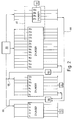
- Each of the drying cylinders in the drying groups can be supplied with pressurized steam from a common steam generation point 60.
- the respective pressure within the cylinder and therefore the cylinder surface temperature is determined by the amount of steam supplied and the order in which the steam is fed to the individual cylinders.
- the example shown has a total of 30 drying cylinders of the same size.
- the first 22, designated 1c to 22c in FIG. 2 are arranged in five single-tier dryer groups 12 to 16.
- the last eight cylinders, designated 23c to 30c, are part of a two-row dryer group.
- the steam is, as shown in the example, fed to a cascade arrangement.
- the drying cylinders are divided into four steam groups, which however do not correspond to the drying groups defined by the drying felts.
- the first steam group comprises the cylinders 1c to 5c, the second steam group the cylinders 6c to 12c, the third steam group 13c to 26c and the fourth steam group the cylinders 27c to 30c.
- the live steam supplied by the steam generation point 60 is first fed to the cylinders 13c to 26c in the third steam group, the pressure value being the highest here.
- This third steam group comprises cylinders in the single-row dryer groups 14, 15 and 16 and the first four cylinders 23 to 26 in the double-row dryer group 40.
- the steam and the condensate become a common condensate separator 63 from the third steam group of the drying cylinders 13c to 26c headed. Then the steam is directed to the second steam group of the drying cylinders 6c to 12c.
- the cylinders 6c to 12c of the second steam group are located partly in the single-row dryer group 13 and partly in the single-row dryer group 14. If necessary, fresh steam can also be supplied to the cylinders 6c to 12c via a feed line and a valve 68.
- a vacuum source 71 can be connected to the drying cylinders 6c to 12c.
- the last four drying cylinders 26c to 30c form the fourth steam group and are supplied with steam separately from the steam generation point 60.
- the steam pressure contained in these drying cylinders is reduced by means of a vacuum device 67.
- the outlets of the drying cylinders 27c to 30c for steam and condensate are connected to the condensate separating device 65 via a line 66.
- the reduced pressure in the drying cylinders 26c to 30c leads to a reduction in the paper web temperature starting from the highest temperature on the drying cylinder 26.
- the individual temperatures and individual vapor pressures in the drying cylinders are then selected depending on the type of paper produced and the machine speed, as well as other factors, so that the exact specification of numerical values cannot be given for every situation. It should be emphasized, however, that the drying cylinders arranged in the end in the two-row drying group, which are in the fourth steam group, have their own something have different pressures and temperatures. Preferably, the pressure and temperature in the cylinders of the fourth steam group are lower than those of the cylinders in the third steam group.
- the vapor pressure difference of the drying cylinders 1c to 5c of the first steam group is in the range from -0.483 bar to 1.38 bar (-7.0 to 20 psig); in the drying cylinders 6c to 12c of the second steam group in a range from -0.103 bar to 3.79 bar (-1.5 to 55 psig); in the drying cylinders 13c to 26c of the third steam group in a range from 0.207 bar to 5.17 bar (3-75 psig); and in the fourth steam group drying cylinders 27c to 30c in the range of -0.483 bar to 4.69 bar (-7 to 68 psig).
- the drying cylinders of the fourth steam group which only comprises the last four drying cylinders of the last two-row drying group, have a lower pressure than the drying cylinders in the third steam group and than the drying cylinders in the second steam group.
- the print areas mentioned above partially overlap. In a special application, however, these pressures can be chosen so that they do not overlap.
- the special pressure levels and pressure differences are only given as examples and are not absolutely necessary.
- the basic idea of the invention lies rather in the pressure value differences, in particular between the third and fourth steam groups, and not in the absolute pressure values.
- the total number of drying cylinders and their size in the single-row and double-row groups can vary with different applications without having to leave the basic idea of the present application.
- the drying section 10 shown comprises five single-row dryer groups 12 to 16 with a total of 22 drying cylinders 1c to 22c, followed by a double-row dryer group 40 with eight cylinders 23c to 30c, the upstream four cylinders 23c to 26c of the double-row dryer group being at a higher pressure and the downstream four cylinders 27c to 30c have a lower pressure.
- the paper web runs in a known manner to subsequent post-treatment sections, for example a coating press, a coating section or a calender section.
Landscapes
- Paper (AREA)
- Drying Of Solid Materials (AREA)
Applications Claiming Priority (2)
| Application Number | Priority Date | Filing Date | Title |
|---|---|---|---|
| US08/164,412 US5379528A (en) | 1993-12-09 | 1993-12-09 | Paper making machine drying section steam pressure profile |
| US164412 | 1993-12-09 |
Publications (3)
| Publication Number | Publication Date |
|---|---|
| EP0657580A2 true EP0657580A2 (fr) | 1995-06-14 |
| EP0657580A3 EP0657580A3 (fr) | 1996-12-18 |
| EP0657580B1 EP0657580B1 (fr) | 2000-05-10 |
Family
ID=22594370
Family Applications (1)
| Application Number | Title | Priority Date | Filing Date |
|---|---|---|---|
| EP94119391A Expired - Lifetime EP0657580B1 (fr) | 1993-12-09 | 1994-12-08 | Section de séchage d'une machine à papier |
Country Status (7)
| Country | Link |
|---|---|
| US (1) | US5379528A (fr) |
| EP (1) | EP0657580B1 (fr) |
| JP (1) | JPH07229081A (fr) |
| AT (1) | ATE192802T1 (fr) |
| CA (1) | CA2137311A1 (fr) |
| DE (1) | DE59409339D1 (fr) |
| FI (1) | FI119847B (fr) |
Cited By (2)
| Publication number | Priority date | Publication date | Assignee | Title |
|---|---|---|---|---|
| DE102008000227A1 (de) | 2008-02-04 | 2009-08-06 | Voith Patent Gmbh | Vorrichtung zur Versorgung von mindestens einer Heizgruppe einer Einrichtung zur Herstellung von Faserstoffbahnen |
| DE102014202906A1 (de) | 2014-02-18 | 2015-08-20 | Voith Patent Gmbh | Trockenzylinder zur Trocknung einer Faserstoffbahn |
Families Citing this family (10)
| Publication number | Priority date | Publication date | Assignee | Title |
|---|---|---|---|---|
| US5542193A (en) * | 1992-04-24 | 1996-08-06 | Beloit Technologies, Inc. | Dryer group for curl control |
| US5884415A (en) * | 1992-04-24 | 1999-03-23 | Beloit Technologies, Inc. | Paper making machine providing curl control |
| JP3094798B2 (ja) * | 1994-08-16 | 2000-10-03 | 王子製紙株式会社 | 抄紙機の抄替時の製品水分の制御方法およびその装置 |
| FI120316B (fi) * | 2004-12-31 | 2009-09-15 | Metso Paper Inc | Menetelmä paperikoneen kuivatusosan ajettavuuden parantamiseksi |
| JP5101318B2 (ja) * | 2008-01-28 | 2012-12-19 | グンゼ株式会社 | 乾燥装置、及び乾燥方法 |
| DE102008042285A1 (de) | 2008-09-23 | 2010-03-25 | Voith Patent Gmbh | Beheizbarer Zylinder zur Aufheizung einer Papier-, Karton-, Tissue- oder anderen Materialbahn |
| DE102008043915A1 (de) | 2008-11-20 | 2010-05-27 | Voith Patent Gmbh | Temperaturmesseinrichtung, Vorrichtung mit einer derartigen Temperaturmesseinrichtung und Verfahren zur Temperaturmessung in einer Leiteinrichtung mit einem Querschnitt mit einer derartigen Temperaturmesseinrichtung |
| DE102008043918A1 (de) | 2008-11-20 | 2010-05-27 | Voith Patent Gmbh | Trockenanordnung mit äußerer und innerer Druckhaube |
| DE102016125172A1 (de) * | 2016-12-21 | 2018-06-21 | Voith Patent Gmbh | Verfahren zum Betrieb eines Heizgruppenteilsystems und Heizgruppenteilsystem |
| AT527976A1 (de) * | 2024-01-30 | 2025-08-15 | Mondi Ag | Trockenpartie-Abschnitt zur Herstellung von Kraftpapier |
Citations (4)
| Publication number | Priority date | Publication date | Assignee | Title |
|---|---|---|---|---|
| DE1194692B (de) | 1961-12-22 | 1965-06-10 | Siemens Ag | Temperaturregeleinrichtung fuer die Trockenzylinder einer Papiermaschine |
| AT384254B (de) | 1985-07-03 | 1987-10-27 | Andritz Ag Maschf | Einrichtung zur nutzung von ueberschussdampf |
| WO1993022497A1 (fr) | 1992-04-24 | 1993-11-11 | Beloit Technologies, Inc. | Section de sechage a etage unique pour empecher le gondolage |
| DE9414963U1 (de) | 1994-09-16 | 1994-11-03 | J.M. Voith Gmbh, 89522 Heidenheim | Trockenpartie |
Family Cites Families (6)
| Publication number | Priority date | Publication date | Assignee | Title |
|---|---|---|---|---|
| US2885790A (en) * | 1957-05-24 | 1959-05-12 | Hervey G Cram | Drainage system and moisture control |
| US3828843A (en) * | 1972-08-14 | 1974-08-13 | A Asfura | Process for handling fluids in heat transfer equipment |
| US4314878A (en) * | 1978-01-26 | 1982-02-09 | Westvaco Corporation | Method of operating a papermachine drying line |
| US4447964A (en) * | 1981-11-23 | 1984-05-15 | Gardner Thomas A | Dryer drainage by recirculation with primary and secondary dryers |
| DE3520070A1 (de) * | 1984-06-06 | 1985-12-12 | Valmet Oy, Helsinki | Papierbahntrockenverfahren und -trockenpartien |
| US5291666A (en) * | 1993-04-23 | 1994-03-08 | International Paper Company | Apparatus for drying roll material |
-
1993
- 1993-12-09 US US08/164,412 patent/US5379528A/en not_active Expired - Lifetime
-
1994
- 1994-12-05 CA CA002137311A patent/CA2137311A1/fr not_active Abandoned
- 1994-12-08 FI FI945764A patent/FI119847B/fi not_active IP Right Cessation
- 1994-12-08 DE DE59409339T patent/DE59409339D1/de not_active Expired - Lifetime
- 1994-12-08 EP EP94119391A patent/EP0657580B1/fr not_active Expired - Lifetime
- 1994-12-08 AT AT94119391T patent/ATE192802T1/de not_active IP Right Cessation
- 1994-12-09 JP JP6331740A patent/JPH07229081A/ja active Pending
Patent Citations (4)
| Publication number | Priority date | Publication date | Assignee | Title |
|---|---|---|---|---|
| DE1194692B (de) | 1961-12-22 | 1965-06-10 | Siemens Ag | Temperaturregeleinrichtung fuer die Trockenzylinder einer Papiermaschine |
| AT384254B (de) | 1985-07-03 | 1987-10-27 | Andritz Ag Maschf | Einrichtung zur nutzung von ueberschussdampf |
| WO1993022497A1 (fr) | 1992-04-24 | 1993-11-11 | Beloit Technologies, Inc. | Section de sechage a etage unique pour empecher le gondolage |
| DE9414963U1 (de) | 1994-09-16 | 1994-11-03 | J.M. Voith Gmbh, 89522 Heidenheim | Trockenpartie |
Cited By (2)
| Publication number | Priority date | Publication date | Assignee | Title |
|---|---|---|---|---|
| DE102008000227A1 (de) | 2008-02-04 | 2009-08-06 | Voith Patent Gmbh | Vorrichtung zur Versorgung von mindestens einer Heizgruppe einer Einrichtung zur Herstellung von Faserstoffbahnen |
| DE102014202906A1 (de) | 2014-02-18 | 2015-08-20 | Voith Patent Gmbh | Trockenzylinder zur Trocknung einer Faserstoffbahn |
Also Published As
| Publication number | Publication date |
|---|---|
| JPH07229081A (ja) | 1995-08-29 |
| ATE192802T1 (de) | 2000-05-15 |
| US5379528A (en) | 1995-01-10 |
| FI945764A7 (fi) | 1995-06-10 |
| FI945764A0 (fi) | 1994-12-08 |
| CA2137311A1 (fr) | 1995-06-10 |
| DE59409339D1 (de) | 2000-06-15 |
| EP0657580B1 (fr) | 2000-05-10 |
| FI119847B (fi) | 2009-04-15 |
| EP0657580A3 (fr) | 1996-12-18 |
Similar Documents
| Publication | Publication Date | Title |
|---|---|---|
| DE69019728T2 (de) | Vorrichtung zum Trocknen einer Bahn. | |
| DE3856506T2 (de) | Vorrichtung zur Trocknung einer Bahn | |
| DE69315335T2 (de) | Ein-sieb-trockenpartie für wellungskontrolle | |
| EP0657580B1 (fr) | Section de séchage d'une machine à papier | |
| EP0989232B1 (fr) | Section de séchage | |
| DE102020111746A1 (de) | Maschine zur herstellung oder behandlung einer faserstoffbahn | |
| DE69017219T2 (de) | Verbesserungen der herstellung von materialbahnen. | |
| EP1020559B1 (fr) | Dispositif pour secher et lisser des bandes fibreuses | |
| EP0989233B1 (fr) | Section de séchage et sécheur à convection pour une telle section de séchage | |
| DE69617522T2 (de) | Trockenpartie mit einer Kombination von Einsieb- und Doppelsiebtrockengruppen | |
| AT396696B (de) | Verfahren und vorrichtung zum be- und entlüften einer mindestens eine trockengruppe umfassenden trockenpartie einer papiermaschine | |
| DE69811426T2 (de) | Curl and profile correction with high velocity hoods | |
| DE102021109340B4 (de) | Maschine und Verfahren zur Herstellung einer Faserstoffbahn | |
| EP1527232B1 (fr) | Partie de séchage | |
| EP0726354B1 (fr) | Groupe de séchage d'une section de séchage de matériaux en bande et utilisation d'un groupe de séchage pour réduire graduellement la pression de vapeur à l'intérieur de la bande | |
| WO2007003504A1 (fr) | Procede de fabrication d'une bande continue de papier, en particulier de papier heliographique | |
| EP0802279A2 (fr) | Section de séchage | |
| DE3807858A1 (de) | Verfahren zum trocknen einer materialbahn und vorrichtung zur durchfuehrung dieses verfahrens | |
| EP1741828B1 (fr) | Machine pour la fabrication d'une bande | |
| EP3601666A1 (fr) | Traitement de bande | |
| DE102023101609A1 (de) | Maschine und Verfahren zur Herstellung oder Behandlung einer Faserstoffbahn | |
| DE102004027938A1 (de) | Trockenpartie | |
| DE102022127695A1 (de) | Maschine und Verfahren zur Herstellung oder Behandlung einer Wellpappenrohpapierbahn mit verkürzten Trockensieben | |
| WO2025160607A1 (fr) | Section de séchage pour la production de papier kraft | |
| DE10325572A1 (de) | Vorrichtung und Verfahren zur Herstellung und/oder Behandlung einer Faserstoffbahn |
Legal Events
| Date | Code | Title | Description |
|---|---|---|---|
| PUAI | Public reference made under article 153(3) epc to a published international application that has entered the european phase |
Free format text: ORIGINAL CODE: 0009012 |
|
| AK | Designated contracting states |
Kind code of ref document: A2 Designated state(s): AT CH DE FR GB IT LI SE |
|
| PUAL | Search report despatched |
Free format text: ORIGINAL CODE: 0009013 |
|
| AK | Designated contracting states |
Kind code of ref document: A3 Designated state(s): AT CH DE FR GB IT LI SE |
|
| 17P | Request for examination filed |
Effective date: 19970424 |
|
| 17Q | First examination report despatched |
Effective date: 19981211 |
|
| GRAG | Despatch of communication of intention to grant |
Free format text: ORIGINAL CODE: EPIDOS AGRA |
|
| GRAG | Despatch of communication of intention to grant |
Free format text: ORIGINAL CODE: EPIDOS AGRA |
|
| GRAG | Despatch of communication of intention to grant |
Free format text: ORIGINAL CODE: EPIDOS AGRA |
|
| GRAH | Despatch of communication of intention to grant a patent |
Free format text: ORIGINAL CODE: EPIDOS IGRA |
|
| GRAH | Despatch of communication of intention to grant a patent |
Free format text: ORIGINAL CODE: EPIDOS IGRA |
|
| GRAH | Despatch of communication of intention to grant a patent |
Free format text: ORIGINAL CODE: EPIDOS IGRA |
|
| GRAH | Despatch of communication of intention to grant a patent |
Free format text: ORIGINAL CODE: EPIDOS IGRA |
|
| GRAA | (expected) grant |
Free format text: ORIGINAL CODE: 0009210 |
|
| ITF | It: translation for a ep patent filed | ||
| AK | Designated contracting states |
Kind code of ref document: B1 Designated state(s): AT CH DE FR GB IT LI SE |
|
| PG25 | Lapsed in a contracting state [announced via postgrant information from national office to epo] |
Ref country code: FR Free format text: LAPSE BECAUSE OF FAILURE TO SUBMIT A TRANSLATION OF THE DESCRIPTION OR TO PAY THE FEE WITHIN THE PRESCRIBED TIME-LIMIT Effective date: 20000510 |
|
| REF | Corresponds to: |
Ref document number: 192802 Country of ref document: AT Date of ref document: 20000515 Kind code of ref document: T |
|
| REG | Reference to a national code |
Ref country code: CH Ref legal event code: EP |
|
| GBT | Gb: translation of ep patent filed (gb section 77(6)(a)/1977) |
Effective date: 20000510 |
|
| REF | Corresponds to: |
Ref document number: 59409339 Country of ref document: DE Date of ref document: 20000615 |
|
| EN | Fr: translation not filed | ||
| PGFP | Annual fee paid to national office [announced via postgrant information from national office to epo] |
Ref country code: GB Payment date: 20001127 Year of fee payment: 7 |
|
| PG25 | Lapsed in a contracting state [announced via postgrant information from national office to epo] |
Ref country code: AT Free format text: LAPSE BECAUSE OF NON-PAYMENT OF DUE FEES Effective date: 20001208 |
|
| PG25 | Lapsed in a contracting state [announced via postgrant information from national office to epo] |
Ref country code: LI Free format text: LAPSE BECAUSE OF NON-PAYMENT OF DUE FEES Effective date: 20001231 Ref country code: CH Free format text: LAPSE BECAUSE OF NON-PAYMENT OF DUE FEES Effective date: 20001231 |
|
| PLBE | No opposition filed within time limit |
Free format text: ORIGINAL CODE: 0009261 |
|
| STAA | Information on the status of an ep patent application or granted ep patent |
Free format text: STATUS: NO OPPOSITION FILED WITHIN TIME LIMIT |
|
| 26N | No opposition filed | ||
| REG | Reference to a national code |
Ref country code: CH Ref legal event code: PL |
|
| PG25 | Lapsed in a contracting state [announced via postgrant information from national office to epo] |
Ref country code: GB Free format text: LAPSE BECAUSE OF NON-PAYMENT OF DUE FEES Effective date: 20011208 |
|
| REG | Reference to a national code |
Ref country code: GB Ref legal event code: IF02 |
|
| GBPC | Gb: european patent ceased through non-payment of renewal fee |
Effective date: 20011208 |
|
| PG25 | Lapsed in a contracting state [announced via postgrant information from national office to epo] |
Ref country code: IT Free format text: LAPSE BECAUSE OF NON-PAYMENT OF DUE FEES;WARNING: LAPSES OF ITALIAN PATENTS WITH EFFECTIVE DATE BEFORE 2007 MAY HAVE OCCURRED AT ANY TIME BEFORE 2007. THE CORRECT EFFECTIVE DATE MAY BE DIFFERENT FROM THE ONE RECORDED. Effective date: 20051208 |
|
| PGFP | Annual fee paid to national office [announced via postgrant information from national office to epo] |
Ref country code: SE Payment date: 20121220 Year of fee payment: 19 |
|
| PGFP | Annual fee paid to national office [announced via postgrant information from national office to epo] |
Ref country code: DE Payment date: 20121220 Year of fee payment: 19 |
|
| REG | Reference to a national code |
Ref country code: DE Ref legal event code: R119 Ref document number: 59409339 Country of ref document: DE |
|
| REG | Reference to a national code |
Ref country code: SE Ref legal event code: EUG |
|
| PG25 | Lapsed in a contracting state [announced via postgrant information from national office to epo] |
Ref country code: SE Free format text: LAPSE BECAUSE OF NON-PAYMENT OF DUE FEES Effective date: 20131209 |
|
| REG | Reference to a national code |
Ref country code: DE Ref legal event code: R119 Ref document number: 59409339 Country of ref document: DE Effective date: 20140701 |
|
| PG25 | Lapsed in a contracting state [announced via postgrant information from national office to epo] |
Ref country code: DE Free format text: LAPSE BECAUSE OF NON-PAYMENT OF DUE FEES Effective date: 20140701 |