EP0657597B1 - Befestigungsklammer - Google Patents
Befestigungsklammer Download PDFInfo
- Publication number
- EP0657597B1 EP0657597B1 EP94118331A EP94118331A EP0657597B1 EP 0657597 B1 EP0657597 B1 EP 0657597B1 EP 94118331 A EP94118331 A EP 94118331A EP 94118331 A EP94118331 A EP 94118331A EP 0657597 B1 EP0657597 B1 EP 0657597B1
- Authority
- EP
- European Patent Office
- Prior art keywords
- clip
- tabs
- layer
- opposite
- elongate
- Prior art date
- Legal status (The legal status is an assumption and is not a legal conclusion. Google has not performed a legal analysis and makes no representation as to the accuracy of the status listed.)
- Expired - Lifetime
Links
- 230000003014 reinforcing effect Effects 0.000 claims description 30
- 238000000576 coating method Methods 0.000 claims description 12
- 230000007797 corrosion Effects 0.000 claims description 10
- 238000005260 corrosion Methods 0.000 claims description 10
- 239000011248 coating agent Substances 0.000 claims description 8
- 239000004020 conductor Substances 0.000 claims description 6
- 238000000034 method Methods 0.000 claims description 6
- 229910045601 alloy Inorganic materials 0.000 claims description 5
- 239000000956 alloy Substances 0.000 claims description 5
- HCHKCACWOHOZIP-UHFFFAOYSA-N Zinc Chemical compound [Zn] HCHKCACWOHOZIP-UHFFFAOYSA-N 0.000 claims description 3
- 229910052782 aluminium Inorganic materials 0.000 claims description 3
- XAGFODPZIPBFFR-UHFFFAOYSA-N aluminium Chemical compound [Al] XAGFODPZIPBFFR-UHFFFAOYSA-N 0.000 claims description 3
- 239000010935 stainless steel Substances 0.000 claims description 3
- 229910052725 zinc Inorganic materials 0.000 claims description 3
- 239000011701 zinc Substances 0.000 claims description 3
- RYGMFSIKBFXOCR-UHFFFAOYSA-N Copper Chemical compound [Cu] RYGMFSIKBFXOCR-UHFFFAOYSA-N 0.000 claims description 2
- RTAQQCXQSZGOHL-UHFFFAOYSA-N Titanium Chemical compound [Ti] RTAQQCXQSZGOHL-UHFFFAOYSA-N 0.000 claims description 2
- 239000010949 copper Substances 0.000 claims description 2
- 239000010936 titanium Substances 0.000 claims description 2
- 239000004411 aluminium Substances 0.000 claims 2
- 239000010953 base metal Substances 0.000 claims 2
- 229910000881 Cu alloy Inorganic materials 0.000 claims 1
- 229910000990 Ni alloy Inorganic materials 0.000 claims 1
- 229910001069 Ti alloy Inorganic materials 0.000 claims 1
- 229910001256 stainless steel alloy Inorganic materials 0.000 claims 1
- 229910052751 metal Inorganic materials 0.000 description 38
- 239000002184 metal Substances 0.000 description 38
- 229910000831 Steel Inorganic materials 0.000 description 13
- 230000015572 biosynthetic process Effects 0.000 description 13
- 239000010959 steel Substances 0.000 description 13
- 239000004567 concrete Substances 0.000 description 9
- 238000004210 cathodic protection Methods 0.000 description 8
- 230000002787 reinforcement Effects 0.000 description 6
- 239000011253 protective coating Substances 0.000 description 5
- 150000002739 metals Chemical class 0.000 description 4
- 230000001681 protective effect Effects 0.000 description 3
- 229920005989 resin Polymers 0.000 description 3
- 239000011347 resin Substances 0.000 description 3
- 239000010963 304 stainless steel Substances 0.000 description 2
- PXHVJJICTQNCMI-UHFFFAOYSA-N Nickel Chemical compound [Ni] PXHVJJICTQNCMI-UHFFFAOYSA-N 0.000 description 2
- 229910000589 SAE 304 stainless steel Inorganic materials 0.000 description 2
- 238000006243 chemical reaction Methods 0.000 description 2
- 239000000470 constituent Substances 0.000 description 2
- 230000006866 deterioration Effects 0.000 description 2
- 239000003792 electrolyte Substances 0.000 description 2
- 238000006056 electrooxidation reaction Methods 0.000 description 2
- 238000010348 incorporation Methods 0.000 description 2
- NJPPVKZQTLUDBO-UHFFFAOYSA-N novaluron Chemical compound C1=C(Cl)C(OC(F)(F)C(OC(F)(F)F)F)=CC=C1NC(=O)NC(=O)C1=C(F)C=CC=C1F NJPPVKZQTLUDBO-UHFFFAOYSA-N 0.000 description 2
- 230000000087 stabilizing effect Effects 0.000 description 2
- 229910001220 stainless steel Inorganic materials 0.000 description 2
- 239000004593 Epoxy Substances 0.000 description 1
- 239000010405 anode material Substances 0.000 description 1
- 238000005452 bending Methods 0.000 description 1
- 238000010276 construction Methods 0.000 description 1
- 239000004035 construction material Substances 0.000 description 1
- 229910052802 copper Inorganic materials 0.000 description 1
- 230000001419 dependent effect Effects 0.000 description 1
- 230000008021 deposition Effects 0.000 description 1
- 238000004090 dissolution Methods 0.000 description 1
- 230000007613 environmental effect Effects 0.000 description 1
- 239000003822 epoxy resin Substances 0.000 description 1
- 239000007788 liquid Substances 0.000 description 1
- 230000007774 longterm Effects 0.000 description 1
- 239000000463 material Substances 0.000 description 1
- 239000011159 matrix material Substances 0.000 description 1
- 229910052759 nickel Inorganic materials 0.000 description 1
- 230000037361 pathway Effects 0.000 description 1
- 230000000149 penetrating effect Effects 0.000 description 1
- 230000035515 penetration Effects 0.000 description 1
- 229920000647 polyepoxide Polymers 0.000 description 1
- 239000011150 reinforced concrete Substances 0.000 description 1
- 239000012858 resilient material Substances 0.000 description 1
- 150000003839 salts Chemical class 0.000 description 1
- 238000010998 test method Methods 0.000 description 1
- 229910052719 titanium Inorganic materials 0.000 description 1
- 230000003313 weakening effect Effects 0.000 description 1
Images

Classifications
-
- H—ELECTRICITY
- H01—ELECTRIC ELEMENTS
- H01R—ELECTRICALLY-CONDUCTIVE CONNECTIONS; STRUCTURAL ASSOCIATIONS OF A PLURALITY OF MUTUALLY-INSULATED ELECTRICAL CONNECTING ELEMENTS; COUPLING DEVICES; CURRENT COLLECTORS
- H01R4/00—Electrically-conductive connections between two or more conductive members in direct contact, i.e. touching one another; Means for effecting or maintaining such contact; Electrically-conductive connections having two or more spaced connecting locations for conductors and using contact members penetrating insulation
- H01R4/24—Connections using contact members penetrating or cutting insulation or cable strands
- H01R4/2416—Connections using contact members penetrating or cutting insulation or cable strands the contact members having insulation-cutting edges, e.g. of tuning fork type
- H01R4/2445—Connections using contact members penetrating or cutting insulation or cable strands the contact members having insulation-cutting edges, e.g. of tuning fork type the contact members having additional means acting on the insulation or the wire, e.g. additional insulation penetrating means, strain relief means or wire cutting knives
- H01R4/245—Connections using contact members penetrating or cutting insulation or cable strands the contact members having insulation-cutting edges, e.g. of tuning fork type the contact members having additional means acting on the insulation or the wire, e.g. additional insulation penetrating means, strain relief means or wire cutting knives the additional means having two or more slotted flat portions
- H01R4/2454—Connections using contact members penetrating or cutting insulation or cable strands the contact members having insulation-cutting edges, e.g. of tuning fork type the contact members having additional means acting on the insulation or the wire, e.g. additional insulation penetrating means, strain relief means or wire cutting knives the additional means having two or more slotted flat portions forming a U-shape with slotted branches
-
- Y—GENERAL TAGGING OF NEW TECHNOLOGICAL DEVELOPMENTS; GENERAL TAGGING OF CROSS-SECTIONAL TECHNOLOGIES SPANNING OVER SEVERAL SECTIONS OF THE IPC; TECHNICAL SUBJECTS COVERED BY FORMER USPC CROSS-REFERENCE ART COLLECTIONS [XRACs] AND DIGESTS
- Y10—TECHNICAL SUBJECTS COVERED BY FORMER USPC
- Y10T—TECHNICAL SUBJECTS COVERED BY FORMER US CLASSIFICATION
- Y10T24/00—Buckles, buttons, clasps, etc.
- Y10T24/34—Combined diverse multipart fasteners
- Y10T24/3427—Clasp
- Y10T24/3439—Plural clasps
- Y10T24/344—Resilient type clasp
-
- Y—GENERAL TAGGING OF NEW TECHNOLOGICAL DEVELOPMENTS; GENERAL TAGGING OF CROSS-SECTIONAL TECHNOLOGIES SPANNING OVER SEVERAL SECTIONS OF THE IPC; TECHNICAL SUBJECTS COVERED BY FORMER USPC CROSS-REFERENCE ART COLLECTIONS [XRACs] AND DIGESTS
- Y10—TECHNICAL SUBJECTS COVERED BY FORMER USPC
- Y10T—TECHNICAL SUBJECTS COVERED BY FORMER US CLASSIFICATION
- Y10T403/00—Joints and connections
- Y10T403/71—Rod side to plate or side
- Y10T403/7158—Diagonal connector
Definitions
- This invention relates to conductive connecting clips which are used in the formation of junctions for elongate reinforcing members, such as metal rod and reinforcing members, to form extended grids.
- These grids may be provided with means for cathodic protection which restricts corrosion and increases the useful life of reinforced concrete structures by stabilizing the metal grid.
- Metal rods in the form of a grid structure have long been used as internal reinforcement for concrete structures, such as beams, girders, columns, support surfaces and the like. These concrete forms are frequently subject to weakening due to the gradual deterioration of the reinforcing metal grid. Deterioration of the grid occurs because most metals, exposed to natural environments without protection, enter into reaction with constituents in the environment. This reaction results in the formation of corrosion products typical of the ores from which the metals were originally formed. Thus constituents, present in concrete, will attack the metal reinforcing structure, especially in the presence of moisture and soluble salts. This phenomenon may also be referred to as electrochemical corrosion. Since moisture is readily absorbed by concrete, it is necessary to provide a means of protection for the metal reinforcement.
- the dissolution of a metal in a liquid environment occurs at discrete sites which act as anodes.
- a corrosion cell consists of an anode and a cathode in contact with each other and with a common electrolyte. The metal forming the anode will dissolve while the cathode remains intact. It is necessary, therefore, to provide means whereby the metal to be protected becomes the cathode under conditions of corrosion cell formation.
- EMF electromotive force
- ICCPS impressed-current cathodic protection
- the negative terminal of a DC power source is connected to the metal grid and the positive terminal is connected to a suitable anode adjacent to the reinforced structure.
- This arrangement establishes an electrical bias by which the reinforcing grid becomes the cathode upon formation of a corrosion cell.
- US-A-3,553,094 discloses a device which may be strapped onto a coated pipe to provide a metallic component which preferentially becomes the anode during electrolytic cell formation in the presence of moisture. Penetration of the protective coating of the pipe occurs during tightening of the device against the pipe. Sharp projections, in contact with the protective pipe coating, cut through the coating and penetrate the metal surface to provide metal-to-metal, electrical connection to the pipe. A sacrificial anode, attached to the device, will be preferentially consumed, via electrochemical action, leaving the metal pipe intact.
- anode is produced in the form of a mesh.
- the mesh is constructed of elongate electrodes held together at points of intersection or junctions by resilient conductive clips which secure and electrically connect the elongate electrodes.
- the mesh anode When suitably connected to e.g. a reinforcing grid of steel the mesh anode will protect the steel grid from corrosion. Protection is achieved by connecting the steel grid to a mesh anode positioned at the surface of the concrete form or embedded in concrete closely proximate the grid.
- the properties and form of the resilient conductive clips, used to develop and stabilize the mesh anode, are selected to provide long term, optimum connection at the junctions.
- FR-A-2 151 236 discloses a connecting clip used to connect tubular elements, such as steel rods acting as reinforcement members in steel concrete construction.
- the metal clip is formed of a base on which at two opposite edges side tabs are affixed, extending perpendicular to the base of the clip.
- the side tabs each have a U-shaped contact element on their free ends, providing means for making resilient mechanical contact with the lower of two tubular elements crossing at an intersection.
- a clip for connecting elongate reinforcing members said clip consisting of electrically conductive material and comprising a rectangular plate having opposite surfaces, opposite side edges and opposite end edges, an end tab affixed to and extending from each of said opposite end edges perpendicularly to said one said surface, said end tabs having a U-shaped contact element formed in the free end thereof, said contact element having means for making resilient mechanical contact with elongate reinforcing members upon applying the end tabs onto a reinforcing member.
- the present invention utilizes a conductive connecting clip which is designed to accommodate two pieces of steel rod.
- a clip for connecting elongate reinforcing members comprises,
- connecting clips With sufficient connecting clips and multiple lengths of e.g. steel rod, it is possible to construct a matrix or grid wherein the connecting clips hold rods together at intersections or junctions with each other. Once formed, this grid is useful as a means of reinforcement for load bearing structures such as concrete forms. It is also within the scope of this invention to construct grids of steel rod of circular cross-section or tubes of suitable dimensions.
- the electrically conductive grid may be formed using either coated or uncoated steel rod. Since epoxy coated steel rods are electrically insulated, it is usually more difficult to establish electrical continuity throughout the grid. This problem is overcome by providing a surface irregularity, in the form of sharp projections or points, in combination with the electrically conducting connecting clip which is used to connect the rods at points where they intersect. The sharp projections abrade or penetrate the protective coating sufficiently to allow electrical contact to occur.
- Each connecting clip accommodates two pieces of steel rod, in U-shaped recesses in orthogonal relationship, placed one adjacent to the other e.g. an upper rod is positioned at right angles to a lower rod.
- a layer of parallel rods, side-by-side, with connecting clips at fixed positions is equipped to receive a similar array of parallel rods, at right angles to the first. Attachment of the second layer adjacent to the first layer results in the formation of a rigid electrically connected metallic grid.
- a pedestal support may be attached to the base of each connecting clip. With adjustment of the height of the support, it is possible to position the metallic grid in an optimum position for reinforcement, prior to encasing it in concrete or other construction material requiring reinforcement from the rods.
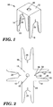
- FIG 1 shows a connecting clip according to the present invention.
- This clip is used in developing a network of reinforcing rods as shown in Figure 4.
- the connecting clip 10 is made of highly resilient material such as stainless steel. It comprises a rectangular plate 12 to which opposed side tabs 14 and 16 are affixed and extend perpendicular to the plate 12.
- opposed end tabs 18 and 20 are affixed to and extend perpendicularly from plate 12, illustrated as a square.
- the end tabs 18 and 20 of the connecting clip 10 are of equal length but longer than the side tabs 14 and 16 which extend an equal distance from the surface of the square plate 12.
- the distal or free ends of each of the side tabs 14 and 16 and each of the end tabs 18 and 20 have a U-shaped recess forming a contact element 22, 24, 26 and 28 respectively, therein.
- Connecting clip 10 may be formed from a single metal pattern as depicted in Figure 2. which structure is in the general shape of a cross.
- the central portion, which connects the limbs of the cross, is square plate 12 of Figure 1 having extensions 14, 16, 18 and 20 respectively attached to each of its four sides. Bending of each of the extensions downwards until a vertical relationship is established between an extension and the square plate 12 results in formation of the connecting clip 10 previously described.
- a hole 48 at the center of the metal pattern is provided as a point of connection between a formed clip and an upper end portion of a pedestal support.
- Figure 2 also provides a detail view of the U-shaped contact element 22 of side tab 14 which has an open end portion opposing side walls 30 and 32 and a closed portion 34 generally describing a U-shaped recess.
- the opposing side walls 30 and 32 of the contact element 22 are each provided with at least one serration 36 and 37 as a means of abrading coatings or oxide from the rods which are pressed into position between the opposing side walls 30 and 32 of each contact element.
- the abrading means are in the form of stepped teeth to progressively cut through the coatings or oxides on the rods.
- the incorporation of a longitudinal slot 38 in the closed portion 34 of the U-shaped recess facilitates the resilient gripping action of the U-shaped contact element 22.
- a junction may be formed between two sections of metal rod according to Figure 3 using a clip of the invention.
- the connecting clip 10 is applied over rod section 50 until it is firmly held between two U-shaped contact elements 22 and 24 of side tabs 14 and 16.
- rod section 52 is positioned between two U-shaped contact elements 26 and 28 in opposing end tabs 18 and 20.
- Rods forming the junction may be uncoated rod as shown by bare rod section 50 or coated rod as exemplified by insulated rod 52 or combinations thereof as shown. The formation of a plurality of junctions along sections of rod results in the metal grid 60 shown in Figure 4.
- a metal grid may be cathodically protected by incorporation of an insert as a sacrificial anode 70 in the clip 10 according to Figure 5.
- an insert as a sacrificial anode 70 in the clip 10 according to Figure 5.
- Suitable anode materials include zinc, aluminum and alloys thereof. This provides protective means at each junction.
- electrically conducting connecting clips made from 304 stainless steel, are effective for use with coated and uncoated metal rods. With uncoated rods the formation of electrically conductive junctions is relatively easy. The sharp projections on opposing side-walls of the U-shaped contact elements readily displace any oxide coating and easily penetrate the surface of the metal rod.
- the penetrating power of the sharp projections 36 and 37 must be sufficient to cause metal-to-metal contact between the rod and the connecting clip 10. Failure to do this will result in junction formation without electrical continuity since most protective resin coatings are electrically insulating.
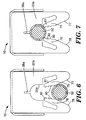
- FIG. 6 An alternative embodiment of the end tabs 18 and 20 for the clip 10 is illustrated in Figures 6 and 7. While this form may be used on the side tabs 14 and 15 as well, it is not necessary as this embodiment comprises means for maintaining the rod sections in the clip.
- the end tabs 18 and 20 have the retaining arms.
- the end tab will be identified as 20a, having a U-shaped contact element 28a, terminating with a slot 38a, and having a pair of resilient arms 75 and 76 positioned at the free ends of the tab 20a formed by cutting the U-shaped contact element 28a.
- the arms 75 and 76 have an elbow at the free end and the arms extend in a converging manner from the free end of the tab toward the U-shaped contact element 28a.
- the arms 75 and 76 have opposed surfaces 77 and 78 and terminate at ends spaced less than the opposing side edges defining the U-shaped contact element 28a.
- end tabs when formed as illustrated, hold both of the transversely positioned rods in place as the rod 52 of the bottom layer traps the upper rod in the side tabs of the clip.
Landscapes
- Prevention Of Electric Corrosion (AREA)
Claims (10)
- Clip zum Verbinden länglicher Verstärkungsteile, wobei der Clip elektrisch leitendes Material aufweist, mit: einer rechteckigen Platte (12) mit einander gegenüberliegenden Flächen, einander gegenüberliegenden Seitenrändern und einander gegenüberliegenden Endrändern, Seiten-Ansätzen (14,16), die an jedem der einander gegenüberliegenden Seitenränder befestigt sind und von diesem rechtwinklig zu einer der Flächen der Platte (12) abstehen, End-Ansätzen (18,20), die an jedem der einander gegenüberliegenden Endränder befestigt sind und von diesem rechtwinklig zu der genannten Fläche um einen Abstand vorstehen, der größer ist als die Seiten-Ansätze (14,16), wobei die Seiten-Ansätze (14, 16) und die End-Ansätze (18,20) einen an ihrem freien Ende ausgebildeten U-förmigen Kontaktteil (22,24,26,28) mit Einrichtungen aufweisen, die bei Anlegen der Seiten-Ansätze (14,16) an ein Verstärkungsteil und der End-Ansätze (18,20) an ein zweites Verstärkungsteil einen elastischen mechanischen Kontakt mit den länglichen Verstärkungsteilen herstellen.
- Clip nach Anspruch 1, dadurch gekennzeichnet, daß das leitende Material der Platte (12) und der Seiten-Ansätze (14,16) und der End-Ansätze (18,20) aus der Gruppe Kupfer, Titan, Edelstahl oder Kupferlegierungen gewählt ist.
- Clip nach Anspruch 1 oder 2, dadurch gekennzeichnet, daß jeder U-förmige Kontaktteil (22,24,26,28) eine Wandanordnung aufweist, die einen offenen Endteil mit einander gegenüberliegenden Seitenwänden (30,32,77,78) und eine Endwand (34,28a) definiert, die im wesentlichen eine U-förmige Ausnehmung bilden, wobei jede der Seitenwände (30,32,77,78) mindestens eine Unregelmäßigkeit (36,37,38) aufweist, die als Vorrichtung zum Anreiben an einen in den offenen Endteil eingeführten Teil dient.
- Clip nach Anspruch 3, dadurch gekennzeichnet, daß ausgehend von dem durch die Endwand (34,28a) geschlossenen Teil, der dem offenen Endteil mit Abstand gegenüberliegt, ein länglicher Schlitz (38,38a) verläuft.
- Clip nach einem der Ansprüche 1 bis 4, dadurch gekennzeichnet, daß der Clip (10) eine Korrosionsschutz-Vorrichtung (56,70) hält und elektrisch mit dieser verbunden ist.
- Clip nach Anspruch 5, dadurch gekennzeichnet, daß die Korrosionsschutz-Vorrichtung eine Opferanode (70) aus einem Basismetall ist, das aus der Gruppe Zink, Aluminium oder Legierungen derselben gewählt ist.
- Clip nach einem der Ansprüche 1 bis 6, dadurch gekennzeichnet, daß der Clip (10) eine auf seine Oberfläche aufgetragene metallische Beschichtung (56) aus einem Basismetall ist, das aus der Gruppe Zink, Aluminium oder Legierungen derselben gewählt ist.
- Clip nach einem der Ansprüche 1 bis 7, dadurch gekennzeichnet, daß an einem End-Ansatz (20a) nahe der Öffnung Haltearme (75, 76) ausgebildet sind, die in den U-förmigen Kontaktteil führen.
- Verbindungsanordnung für ein aus länglichen Verstärkungsteilen (50,52) gebildetes Gitter, mit:einem ein elektrisch leitendes Material aufweisenden Clip (10) zum Verbinden der Verstärkungsteile (50,52), wobei der Clip (10) aufweist:eine rechteckige Platte (12) mit einander gegenüberliegenden Flächen, einander gegenüberliegenden Seitenrändern und einander gegenüberliegenden Endrändern,Seiten-Ansätze (14,16), die an jedem der einander gegenüberliegenden Seitenränder befestigt sind und von diesem rechtwinklig zu einer der Flächen der rechteckigen Platte (12) abstehen,End-Ansätze (18,20), die an jedem der einander gegenüberliegenden Endränder befestigt sind und von diesem rechtwinklig zu einer der Flächen um einen Abstand vorstehen, der größer ist als die Seiten-Ansätze (14,16),wobei jeder der Seiten-Ansätze (14,16) und der End-Ansätze (18,20) einen an ihrem freien Ende ausgebildeten U-förmigen Kontaktteil (22,24,26,28,28a) mit Einrichtungen zur Herstellung eines elastischen mechanischen und elektrischen Kontakts mit den länglichen Verstärkungsteilen aufweist,ein erstes längliches Verstärkungsteil (50), das mit seiner Längsachse parallel zu den Endrändern der rechteckigen Platte positioniert ist, wobei von jedem der U-förmigen Kontaktteile der Seiten-Ansätze (14,16) ein Abschnitt des ersten länglichen Teils gehalten wird,ein zweites längliches Verstärkungsteil (52), das mit seiner Längsachse parallel zu den Seitenrändern der rechteckigen Platte (12) positioniert ist, wobei von jedem der U-förmigen Kontaktteile der End-Ansätze (18,20) ein Abschnitt des zweiten länglichen Verstärkungsteils 52 gehalten wird, wobei das erste längliche Teil und das zweite längliche Teil einander in Querbeziehung überlappen,wobei der Clip (10) insbesondere gemäß einem der Ansprüche 1 bis 8 ausgebildet ist.
- Verfahren zum Bilden eines Gitters aus länglichen Verstärkungsteilen, mit den folgenden Schritten:Bilden eines rechtwinkligen Arrays, das eine erste Lage und eine zweite Lage der länglichen Verstärkungsteile (50,52) aufweist, wobei sämtliche länglichen Verstärkungsteile in paralleler seitlich angrenzender Beziehung zu der ersten Lage und der zweiten Lage angeordnet sind, die Teile der ersten Lage rechtwinklig zu den die zweite Lage bildenden Teilen angeordnet sind und, an mehreren Schnittpunkten zwischen den Teilen, Verbinden der ersten Lage mit der zweiten Lage mittels eines ein elektrisch leitendes Material aufweisenden Clips (10) mit:einer rechteckigen Platte (12) mit einander gegenüberliegenden Flächen, einander gegenüberliegenden Seitenrändern und einander gegenüberliegenden Endrändern,Seiten-Ansätzen (14,16), die an jedem der einander gegenüberliegenden Seitenränder befestigt sind und von diesem rechtwinklig zu einer der Flächen der Platte abstehen, undEnd-Ansätzen (18,20), die an jedem der einander gegenüberliegenden Endränder befestigt sind und von diesem rechtwinklig zu einer der Flächen um einen Abstand vorstehen, der größer ist als die Seiten-Ansätze (14,16),wobei die Seiten-Ansätze (14,16) und die End-Ansätze (18,20) einen an ihrem freien Ende ausgebildeten U-förmigen Kontaktteil (22,24,26,28) zur Herstellung eines elastischen mechanischen Kontakts mit den länglichen Verstärkungsteilen (50,52) aufweisen,wobei der Clip (10) einen Teil eines länglichen Verstärkungsteils aus der ersten Lage mit einem Teil eines länglichen Verstärkungsteils aus der zweiten Lage an dem Kreuzungspunkt derart verbindet, daß sich der U-förmige Kontaktteil jedes der Seiten-Ansätze in elastischem mechanischen Kontakt mit dem Teil des länglichen Verstärkungsteils aus der ersten Lage befindet, und sich der U-förmige Kontaktteil jedes End-Ansatzes in elastischem mechanischen Kontakt mit dem Teil des länglichen Verstärkungsteils aus der zweiten Lage befindet,wobei der Clip (10) insbesondere gemäß einem der Ansprüche 1 bis 8 ausgebildet ist.
Applications Claiming Priority (2)
| Application Number | Priority Date | Filing Date | Title |
|---|---|---|---|
| US158683 | 1993-11-24 | ||
| US08/158,683 US5358423A (en) | 1993-11-24 | 1993-11-24 | Connecting clip |
Publications (2)
| Publication Number | Publication Date |
|---|---|
| EP0657597A1 EP0657597A1 (de) | 1995-06-14 |
| EP0657597B1 true EP0657597B1 (de) | 2000-08-16 |
Family
ID=22569241
Family Applications (1)
| Application Number | Title | Priority Date | Filing Date |
|---|---|---|---|
| EP94118331A Expired - Lifetime EP0657597B1 (de) | 1993-11-24 | 1994-11-22 | Befestigungsklammer |
Country Status (4)
| Country | Link |
|---|---|
| US (1) | US5358423A (de) |
| EP (1) | EP0657597B1 (de) |
| CA (1) | CA2134159C (de) |
| DE (1) | DE69425545T2 (de) |
Cited By (2)
| Publication number | Priority date | Publication date | Assignee | Title |
|---|---|---|---|---|
| DE102011052065A1 (de) | 2011-07-22 | 2013-01-24 | Reuss-Seifert Gmbh | Befestigungseinrichtung |
| US10519660B2 (en) | 2017-06-09 | 2019-12-31 | Gem Technologies, Inc. | Key-locked and band-tightened rebar clamping assemblies |
Families Citing this family (51)
| Publication number | Priority date | Publication date | Assignee | Title |
|---|---|---|---|---|
| US6040525A (en) * | 1996-04-18 | 2000-03-21 | Erico International Corporation | Electrical clip and method |
| US5766422A (en) * | 1996-08-01 | 1998-06-16 | Beloit Technologies, Inc. | Lightweight high temperature pressing |
| RU2149962C1 (ru) * | 1998-07-30 | 2000-05-27 | Ереванский архитектурно-строительный институт | Фиксатор для арматурных стержней |
| US6200156B1 (en) * | 1998-11-27 | 2001-03-13 | Hokuriku Electric Industry Co., Ltd. | Terminal fitment for lead wire connection and high-voltage variable resistor unit with relay terminal fitment |
| JP3670529B2 (ja) * | 1999-09-07 | 2005-07-13 | 矢崎総業株式会社 | 分岐接続器 |
| NL1013890C2 (nl) | 1999-12-20 | 2001-06-21 | Thomas K Nig | Werkwijze en wikkelveer voor het onderling verbinden van langgerekte elementen, zoals wapeningsstaven. |
| US6296513B1 (en) * | 2000-05-17 | 2001-10-02 | Tyco Electronics Amp, K.K. | Electrical terminal for terminating at least two wires therein |
| JP2002186140A (ja) * | 2000-12-15 | 2002-06-28 | Yazaki Corp | 電気接続箱の回路構造及びその回路形成方法 |
| GB2371081B (en) * | 2001-01-11 | 2002-12-24 | Crispin James | Attachment device |
| US6443401B1 (en) * | 2001-01-17 | 2002-09-03 | Doorframer, Inc. | Agricultural clip system and method |
| JP2003074596A (ja) * | 2001-09-03 | 2003-03-12 | Sanden Corp | 電磁クラッチ用ヨーク |
| US6622352B2 (en) * | 2001-09-04 | 2003-09-23 | Clip-N-Stay | Quick-release wire hanger |
| USD480361S1 (en) | 2001-11-20 | 2003-10-07 | Tiger Technology Inc. | Grounding casing for electric facility |
| DE10204262A1 (de) * | 2002-02-02 | 2003-08-07 | Bauer Christian Gmbh & Co | U-Profilförmige Federklammer für Flanschverbindungen |
| US6745985B2 (en) * | 2002-10-15 | 2004-06-08 | Senninger Irrigation Inc. | Hose sling for irrigation system |
| US7210277B2 (en) * | 2003-04-30 | 2007-05-01 | Lifetime Products, Inc. | Partition system |
| US7658038B2 (en) | 2004-03-29 | 2010-02-09 | Lifetime Products, Inc. | System and method for constructing a modular enclosure |
| US7797885B2 (en) | 2004-03-29 | 2010-09-21 | Lifetime Products, Inc. | Modular enclosure |
| US7770334B2 (en) | 2004-03-29 | 2010-08-10 | Lifetime Products, Inc. | Door assembly for a modular enclosure |
| US7926227B2 (en) | 2004-03-29 | 2011-04-19 | Lifetime Products, Inc. | Modular enclosure with living hinges |
| US8091289B2 (en) | 2004-03-29 | 2012-01-10 | Lifetime Products, Inc. | Floor for a modular enclosure |
| WO2006017411A1 (en) * | 2004-08-02 | 2006-02-16 | Minor Jack M | Concrete reinforcing bar clip |
| US7824415B2 (en) * | 2004-09-15 | 2010-11-02 | Boston Scientific Scimed, Inc. | Atraumatic medical device |
| DE102004063668B4 (de) * | 2004-12-31 | 2011-01-13 | J. Pröpster GmbH | Verbindungselement für einen Fundamenterder |
| US20060248844A1 (en) * | 2005-05-03 | 2006-11-09 | Kodi Jon R | Bar clip with flared legs |
| US20080053025A1 (en) * | 2006-04-07 | 2008-03-06 | Rich Howe | Clip |
| FI20060661A0 (fi) * | 2006-07-06 | 2006-07-06 | Asennuspalvelu K Hurskainen | Kiinnike |
| US7874533B1 (en) * | 2006-10-31 | 2011-01-25 | All Rite Products, Inc. | ATV mounting bracket and associated tool storage systems |
| JP2010033776A (ja) * | 2008-07-25 | 2010-02-12 | Sumitomo Wiring Syst Ltd | 圧接端子、スプライス用端子及び電線の圧接構造 |
| US20110014825A1 (en) * | 2009-07-16 | 2011-01-20 | Delphi Technologies, Inc. | Electrical terminal connection with galvanic sacrificial metal |
| US8636877B2 (en) * | 2010-03-31 | 2014-01-28 | Joseph Palmer | Sacrificial anode system |
| NL2006790C2 (nl) * | 2011-05-16 | 2012-11-19 | Wouter Garot | Verankeringssamenstel en bevestigingsorgaan voor een dergelijk verankeringssamenstel. |
| US8932087B2 (en) * | 2012-05-08 | 2015-01-13 | Thomas & Betts International, Inc. | Hot line stirrup connector |
| US20140047675A1 (en) * | 2012-08-16 | 2014-02-20 | Berliner Seilfabrik Gmbh & Co. | Clamp for connecting ropes |
| WO2014055971A1 (en) * | 2012-10-05 | 2014-04-10 | Baruh Bradford G | Clip for joining reinforced members for use in reinforced concrete slabs and/or columns |
| JP5771176B2 (ja) * | 2012-10-29 | 2015-08-26 | 株式会社栃木屋 | ポールの継ぎ手 |
| US10098585B2 (en) | 2013-03-15 | 2018-10-16 | Cadwell Laboratories, Inc. | Neuromonitoring systems and methods |
| US8974245B2 (en) * | 2013-08-05 | 2015-03-10 | Hubbell Incorporated | Grounding electrical connector |
| DE102013216561B4 (de) * | 2013-08-21 | 2018-06-21 | J. Pröpster GmbH | Verbindungs-Komponente für Blitzschutz-Leitungen |
| US11031904B2 (en) | 2014-12-11 | 2021-06-08 | A.K. Stamping Company, Inc. | Grounding clamps |
| USD765614S1 (en) * | 2015-04-29 | 2016-09-06 | Bassey Edet Obong | Ground rod protector |
| CA2990024A1 (en) * | 2015-06-19 | 2016-12-22 | Hubbell Incorporated | Clamp and clamp assembly |
| US9935395B1 (en) | 2017-01-23 | 2018-04-03 | Cadwell Laboratories, Inc. | Mass connection plate for electrical connectors |
| CA3006833A1 (en) * | 2017-06-02 | 2018-12-02 | Busch Systems International Inc. | System for connecting containers |
| US10954051B1 (en) | 2017-11-28 | 2021-03-23 | Doorframer, Inc. | Item protection device and method for use |
| US11992339B2 (en) | 2018-05-04 | 2024-05-28 | Cadwell Laboratories, Inc. | Systems and methods for dynamic neurophysiological stimulation |
| US11253182B2 (en) | 2018-05-04 | 2022-02-22 | Cadwell Laboratories, Inc. | Apparatus and method for polyphasic multi-output constant-current and constant-voltage neurophysiological stimulation |
| US11443649B2 (en) | 2018-06-29 | 2022-09-13 | Cadwell Laboratories, Inc. | Neurophysiological monitoring training simulator |
| US11332295B1 (en) | 2018-10-24 | 2022-05-17 | Doorframer, Inc. | Double door restraining device and method |
| JP1659434S (de) * | 2019-06-04 | 2020-05-18 | ||
| JP7089653B2 (ja) * | 2020-12-02 | 2022-06-23 | デンカ株式会社 | 電気化学的処理システム及び電極用ユニットパネル |
Family Cites Families (12)
| Publication number | Priority date | Publication date | Assignee | Title |
|---|---|---|---|---|
| FR523190A (fr) * | 1920-08-26 | 1921-08-13 | Antoine Degabriel | Ligature d'armatures métalliques pour constructions en béton armé |
| DE848696C (de) * | 1951-01-16 | 1952-09-08 | Goesta Julius Axell | Klemme als Abstandhalter fuer Stahlbeton-Bewehrungsstaebe |
| US3553094A (en) * | 1968-04-22 | 1971-01-05 | Reynolds Metals Co | Device for cathodically protecting a metal pipe |
| US3863416A (en) * | 1969-11-28 | 1975-02-04 | Georgi Oroschakoff | Concrete reinforcement |
| BE759216A (fr) * | 1969-11-28 | 1971-04-30 | Oroschakoff Georgi | Armatures pour constructions en beton arme |
| FR2151236A5 (de) * | 1971-08-24 | 1973-04-13 | Flandin Blety Georges | |
| AR208483A1 (es) * | 1975-11-10 | 1976-12-27 | Amp Inc | Terminal electrico |
| US4110951A (en) * | 1977-07-21 | 1978-09-05 | John Padrun | Connecting clip for joining concrete reinforcing bars |
| US4855024A (en) * | 1986-09-16 | 1989-08-08 | Raychem Corporation | Mesh electrodes and clips for use in preparing them |
| CH681378A5 (en) * | 1989-12-07 | 1993-03-15 | Gabriel Clement | Wire attachment device for structures in reinforced concrete - is flexed on application to upper wire of reinforcement grid and slotted to surround lower wire |
| US5009612A (en) * | 1990-02-07 | 1991-04-23 | Molex Incorporated | Multi-conductor electrical cable connector |
| FR2666933B1 (fr) * | 1990-09-19 | 1994-07-22 | Labinal | Element de liaison electrique de deux conducteurs electriques et connecteur de derivation utilisant un tel element. |
-
1993
- 1993-11-24 US US08/158,683 patent/US5358423A/en not_active Expired - Lifetime
-
1994
- 1994-10-24 CA CA002134159A patent/CA2134159C/en not_active Expired - Fee Related
- 1994-11-22 DE DE69425545T patent/DE69425545T2/de not_active Expired - Fee Related
- 1994-11-22 EP EP94118331A patent/EP0657597B1/de not_active Expired - Lifetime
Cited By (2)
| Publication number | Priority date | Publication date | Assignee | Title |
|---|---|---|---|---|
| DE102011052065A1 (de) | 2011-07-22 | 2013-01-24 | Reuss-Seifert Gmbh | Befestigungseinrichtung |
| US10519660B2 (en) | 2017-06-09 | 2019-12-31 | Gem Technologies, Inc. | Key-locked and band-tightened rebar clamping assemblies |
Also Published As
| Publication number | Publication date |
|---|---|
| CA2134159A1 (en) | 1995-05-25 |
| DE69425545D1 (de) | 2000-09-21 |
| CA2134159C (en) | 2004-04-20 |
| EP0657597A1 (de) | 1995-06-14 |
| US5358423A (en) | 1994-10-25 |
| DE69425545T2 (de) | 2001-04-19 |
Similar Documents
| Publication | Publication Date | Title |
|---|---|---|
| US5358423A (en) | Connecting clip | |
| CA1235088A (en) | Anodes for cathodic protection | |
| US4812212A (en) | Apparatus for cathodically protecting reinforcing members and method for installing same | |
| US4855024A (en) | Mesh electrodes and clips for use in preparing them | |
| US5411646A (en) | Cathodic protection anode and systems | |
| EP0222829B1 (de) | Kathodisches schutzsystem für eine stahlarmierte betonstruktur und verfahren zur installierung | |
| CA1147289A (en) | Anode for high resistivity cathodic protection systems | |
| EP0407348A1 (de) | Netzanode und Netzseparator zur Verwendung mit Stahlbeton | |
| CA2075780C (en) | Anode structure for cathodic protection of steel-reinforced concrete and relevant method of use | |
| AU2005258887B2 (en) | Protection of reinforcing steel | |
| EP0292428B1 (de) | System mit Band-Anode für den kathodischen Schutz von stahlarmiertem Beton | |
| CA2316983A1 (en) | Connector for use in cathodic protection and method of use | |
| WO2021215928A1 (en) | Anode assembly for corrosion control of steel reinforced concrete structures | |
| JPS6347789B2 (de) | ||
| CA1116122A (en) | Cathodic protection anode | |
| JP3152714B2 (ja) | 架空裸電線 | |
| CN215579088U (zh) | 一种防雷引下线 | |
| EP0662162B1 (de) | Eine kontinuierlich arbeitende referenz elektrode für den kathodischen schutz von metallischen strukturen | |
| JP2005276792A (ja) | 接地用圧着端子 | |
| JPH0694702B2 (ja) | プレストレストコンクリ−トの定着具 | |
| JPH11293792A (ja) | 耐食性に優れたコンクリート構造物 | |
| JPS62161972A (ja) | 電気防食用流電陽極の取付方法 | |
| CA2144775A1 (en) | A continuous-action reference electrode for the cathodic protection of metallic structures | |
| JPS61117386A (ja) | サツシ枠固定用アンカ− | |
| JPH02231911A (ja) | 海底ケーブル保護用有機被覆金属線の腐食モニタリング方法 |
Legal Events
| Date | Code | Title | Description |
|---|---|---|---|
| PUAI | Public reference made under article 153(3) epc to a published international application that has entered the european phase |
Free format text: ORIGINAL CODE: 0009012 |
|
| AK | Designated contracting states |
Kind code of ref document: A1 Designated state(s): DE FR GB |
|
| 17P | Request for examination filed |
Effective date: 19951205 |
|
| 17Q | First examination report despatched |
Effective date: 19980316 |
|
| GRAG | Despatch of communication of intention to grant |
Free format text: ORIGINAL CODE: EPIDOS AGRA |
|
| GRAG | Despatch of communication of intention to grant |
Free format text: ORIGINAL CODE: EPIDOS AGRA |
|
| GRAH | Despatch of communication of intention to grant a patent |
Free format text: ORIGINAL CODE: EPIDOS IGRA |
|
| GRAH | Despatch of communication of intention to grant a patent |
Free format text: ORIGINAL CODE: EPIDOS IGRA |
|
| GRAA | (expected) grant |
Free format text: ORIGINAL CODE: 0009210 |
|
| AK | Designated contracting states |
Kind code of ref document: B1 Designated state(s): DE FR GB |
|
| REF | Corresponds to: |
Ref document number: 69425545 Country of ref document: DE Date of ref document: 20000921 |
|
| ET | Fr: translation filed | ||
| PLBE | No opposition filed within time limit |
Free format text: ORIGINAL CODE: 0009261 |
|
| STAA | Information on the status of an ep patent application or granted ep patent |
Free format text: STATUS: NO OPPOSITION FILED WITHIN TIME LIMIT |
|
| 26N | No opposition filed | ||
| PGFP | Annual fee paid to national office [announced via postgrant information from national office to epo] |
Ref country code: FR Payment date: 20011031 Year of fee payment: 8 |
|
| PGFP | Annual fee paid to national office [announced via postgrant information from national office to epo] |
Ref country code: DE Payment date: 20011101 Year of fee payment: 8 |
|
| PGFP | Annual fee paid to national office [announced via postgrant information from national office to epo] |
Ref country code: GB Payment date: 20011107 Year of fee payment: 8 |
|
| REG | Reference to a national code |
Ref country code: GB Ref legal event code: IF02 |
|
| PG25 | Lapsed in a contracting state [announced via postgrant information from national office to epo] |
Ref country code: GB Free format text: LAPSE BECAUSE OF NON-PAYMENT OF DUE FEES Effective date: 20021122 |
|
| PG25 | Lapsed in a contracting state [announced via postgrant information from national office to epo] |
Ref country code: DE Free format text: LAPSE BECAUSE OF NON-PAYMENT OF DUE FEES Effective date: 20030603 |
|
| GBPC | Gb: european patent ceased through non-payment of renewal fee | ||
| PG25 | Lapsed in a contracting state [announced via postgrant information from national office to epo] |
Ref country code: FR Free format text: LAPSE BECAUSE OF NON-PAYMENT OF DUE FEES Effective date: 20030731 |
|
| REG | Reference to a national code |
Ref country code: FR Ref legal event code: ST |