EP0657625A1 - Kühlung eines Mantelrings für Gasturbinenrotor - Google Patents
Kühlung eines Mantelrings für Gasturbinenrotor Download PDFInfo
- Publication number
- EP0657625A1 EP0657625A1 EP94309249A EP94309249A EP0657625A1 EP 0657625 A1 EP0657625 A1 EP 0657625A1 EP 94309249 A EP94309249 A EP 94309249A EP 94309249 A EP94309249 A EP 94309249A EP 0657625 A1 EP0657625 A1 EP 0657625A1
- Authority
- EP
- European Patent Office
- Prior art keywords
- segment
- seal
- end surface
- cooling
- passage
- Prior art date
- Legal status (The legal status is an assumption and is not a legal conclusion. Google has not performed a legal analysis and makes no representation as to the accuracy of the status listed.)
- Granted
Links
- 238000001816 cooling Methods 0.000 title claims abstract description 130
- 239000012530 fluid Substances 0.000 claims abstract description 40
- 238000007599 discharging Methods 0.000 claims abstract description 3
- 238000007789 sealing Methods 0.000 claims description 79
- 230000003068 static effect Effects 0.000 claims description 6
- 230000007704 transition Effects 0.000 claims description 4
- 239000007789 gas Substances 0.000 description 7
- 239000000463 material Substances 0.000 description 5
- 230000006835 compression Effects 0.000 description 4
- 238000007906 compression Methods 0.000 description 4
- 238000010926 purge Methods 0.000 description 4
- 230000004888 barrier function Effects 0.000 description 3
- 210000003746 feather Anatomy 0.000 description 3
- 238000011144 upstream manufacturing Methods 0.000 description 3
- 239000011248 coating agent Substances 0.000 description 2
- 238000000576 coating method Methods 0.000 description 2
- 238000002485 combustion reaction Methods 0.000 description 2
- 239000002826 coolant Substances 0.000 description 2
- 230000007423 decrease Effects 0.000 description 2
- 230000000694 effects Effects 0.000 description 2
- 230000008595 infiltration Effects 0.000 description 2
- 238000001764 infiltration Methods 0.000 description 2
- 230000002238 attenuated effect Effects 0.000 description 1
- 239000000919 ceramic Substances 0.000 description 1
- 230000002301 combined effect Effects 0.000 description 1
- 239000000567 combustion gas Substances 0.000 description 1
- 239000000446 fuel Substances 0.000 description 1
- 238000002347 injection Methods 0.000 description 1
- 239000007924 injection Substances 0.000 description 1
- 230000000153 supplemental effect Effects 0.000 description 1
Images


Classifications
-
- F—MECHANICAL ENGINEERING; LIGHTING; HEATING; WEAPONS; BLASTING
- F01—MACHINES OR ENGINES IN GENERAL; ENGINE PLANTS IN GENERAL; STEAM ENGINES
- F01D—NON-POSITIVE DISPLACEMENT MACHINES OR ENGINES, e.g. STEAM TURBINES
- F01D11/00—Preventing or minimising internal leakage of working-fluid, e.g. between stages
- F01D11/005—Sealing means between non relatively rotating elements
-
- F—MECHANICAL ENGINEERING; LIGHTING; HEATING; WEAPONS; BLASTING
- F01—MACHINES OR ENGINES IN GENERAL; ENGINE PLANTS IN GENERAL; STEAM ENGINES
- F01D—NON-POSITIVE DISPLACEMENT MACHINES OR ENGINES, e.g. STEAM TURBINES
- F01D11/00—Preventing or minimising internal leakage of working-fluid, e.g. between stages
- F01D11/08—Preventing or minimising internal leakage of working-fluid, e.g. between stages for sealing space between rotor blade tips and stator
-
- F—MECHANICAL ENGINEERING; LIGHTING; HEATING; WEAPONS; BLASTING
- F01—MACHINES OR ENGINES IN GENERAL; ENGINE PLANTS IN GENERAL; STEAM ENGINES
- F01D—NON-POSITIVE DISPLACEMENT MACHINES OR ENGINES, e.g. STEAM TURBINES
- F01D25/00—Component parts, details, or accessories, not provided for in, or of interest apart from, other groups
- F01D25/08—Cooling; Heating; Heat-insulation
- F01D25/12—Cooling
-
- Y—GENERAL TAGGING OF NEW TECHNOLOGICAL DEVELOPMENTS; GENERAL TAGGING OF CROSS-SECTIONAL TECHNOLOGIES SPANNING OVER SEVERAL SECTIONS OF THE IPC; TECHNICAL SUBJECTS COVERED BY FORMER USPC CROSS-REFERENCE ART COLLECTIONS [XRACs] AND DIGESTS
- Y02—TECHNOLOGIES OR APPLICATIONS FOR MITIGATION OR ADAPTATION AGAINST CLIMATE CHANGE
- Y02T—CLIMATE CHANGE MITIGATION TECHNOLOGIES RELATED TO TRANSPORTATION
- Y02T50/00—Aeronautics or air transport
- Y02T50/60—Efficient propulsion technologies, e.g. for aircraft
Definitions
- the present invention relates to seals, and in particular to seals for use in gas turbine engines of the type having an annular flow path for working fluid.
- the invention is specifically related to a seal formed from several seal segments that extend circumferentially about the engine's longitudinal axis and confine the working fluid to the flow path of the engine.
- Axial flow, gas turbine engines typically have a compression section, a combustion section and a turbine section.
- An annular flow path for the working fluid extends axially through the sections.
- a stator assembly extends about the annular flow path for confining the working fluid to the flow path and for directing the fluid along the flow path.
- the working fluid As the working fluid flows along the flow path, the working fluid is pressurized in the compression section and burned with fuel in the combustion section to add energy to the working fluid.
- the hot, pressurized working fluid is expanded through the turbine section to produce work. A major portion of this work is used for driving a free turbine or developing thrust for an aircraft.
- a remaining portion of the work generated by the turbine section is not used for these purposes. Instead it is used to compress the working fluid itself.
- a rotor assembly extends between the turbine section and the compression section to transfer this work from the turbine section to the compression section.
- the rotor assembly in the turbine section has rotor blades which extend outwardly across the working medium flow path.
- the rotor blades have airfoils which are angled with respect to the approaching flow to receive work from the working fluid and to drive the rotor assembly about the axis of rotation.
- An outer air seal circumscribes the rotor blades to confine the working fluid to the flow path.
- outer air seals are metallic and may or may not be coated with ceramic thermal barrier materials to inhibit heat transfer from the working fluid to the seal.
- the outer air seal is part of the stator structure and is formed of a plurality of arcuate segments.
- the stator assembly further includes an outer case and a structure for supporting the segments of the outer air seal from the outer case.
- the outer case and the support structure position the seal segments in close proximity to the blades to block the leakage of the working fluid past the tips of the blades. As a result, the segments are in intimate contact with the hot working fluid, receive heat from the working fluid and are cooled to keep the temperature of the segments within acceptable limits. Adjacent segments are separated by an inter-segment gap which requires secondary flow for cooling, purging, and to prevent leakage of the working fluid through the seal into the static structure.
- cooling air increases the service life of the outer air seal in comparison to uncooled outer air seals.
- cooling air decreases the operating efficiency of the engine because a portion of the engine's useful work is used to pressurize the cooling air in the compressor.
- a decrease in the amount of cooling air required to provide a satisfactory service life for components such as the outer air seal increases the work available for other purposes, such as providing thrust or powering a free turbine, and increases the overall engine efficiency.
- the invention provides a seal in or for a gas turbine engine comprising a plurality of arcuate seal segments extending circumferentially about a turbine stage, said segments being spaced circumferentially from one another to define an inter-segment gap between adjacent segments, the segments having cooling passages discharging into said gap, the opposed edges of adjacent segments being configured such that said gap is inclined in the direction of rotation of the turbine.
- the invention provides an engine seal for an axial flow gas turbine engine having an axis of rotation defined therethrough, an annular flow path concentric with said axis for working fluid flowing through at least one turbine stage of said engine, said one turbine stage including a plurality of turbine blades extending outward from said axis, and said flow path bounded by a static structure, and an annular seal secured to said static structure radially outward of said one turbine stage, said seal absorbing heat from said working fluid, said turbine blades rotating in a first direction relative to said seal, said seal comprising: a plurality of arcuate seal segments extending circumferentially about the flow path, each segment spaced radially outward from said turbine blades, each seal segment including an arcuate sealing surface having a first end, a second end opposite the first end, and a radius of curvature equal to the distance between the sealing surface and the axis, a supply surface opposite and in spaced relation to the sealing surface and having a plurality of cooling orifices extending
- the invention provides a circumferential seal comprising: a plurality of arcuate seal segments, each seal segment including an arcuate sealing surface having a first end, and a second end opposite the first end, a supply surface opposite and in spaced relation to the sealing surface and having a plurality of cooling orifices extending therethrough, a first end surface extending along the entire first end, and a second end surface extending along the entire second end, said first and second end surfaces extending from said sealing surface to said supply surface, each of said first and second end surfaces including a substantially planar perpendicular surface and a substantially planar canted surface intersecting at an included angle of between 100 degrees and 140 degrees, said orifices being adjacent said second end surface, a first side surface and a second side surface, each of said side surfaces extending from said sealing surface to said supply surface and from said first end surface to said second end surface, at least one cooling passage extending from the first end surface toward the second end surface, each cooling passage being located between said sealing surface and said supply surface,
- the invention provides a seal segment comprising: a sealing surface having a width and a length, said length terminating in first end and a second end opposite the first end, said sealing surface being arcuate between said first and second ends, a supply surface opposite and in spaced relation to the sealing surface and having a plurality of cooling orifices extending therethrough, a first end surface extending along the entire first end, and a second end surface extending along the entire second end, said first and second end surfaces extending from said sealing surface to said supply surface, each of said first and second end surfaces including a substantially planar perpendicular surface and a substantially planar canted surface intersecting at an included angle of between 100 degrees and 140 degrees, and said orifices being adjacent said second end surface, a first side surface and a second side surface, each of said side surfaces extending from said sealing surface to said supply surface and from said first end surface to said second end surface, at least one cooling passage extending from the first end surface toward the second end surface, each cooling passage being located between said
- this invention in its preferred embodiments provides a cooling enhancement for a gas turbine engine blade outer air seal which is made up of a plurality of arcuate seal segments, and each has one or more internal cooling passages.
- each segment has a supply surface opposite and in spaced relation to a sealing surface, and first and second end surfaces extending from the sealing surface to the supply surface.
- Each of the end surfaces includes a substantially planar perpendicular surface and a substantially planar canted surface intersecting at an included angle of between 100 degrees and 140 degrees, and the supply surface has a plurality of cooling orifices adjacent said second end surface.
- At least one cooling passage extends from the first end surface toward the second end surface, and each cooling passage intersects the first end surface and terminates short of the second end surface.
- Each cooling passage communicates with the supply surface through at least one of the cooling orifices. Protruding from at least one of the substantially canted surfaces is a plurality of stand-off pedestals that are integral with that canted surface.
- Figure 1 is a cross-sectional view of a portion of a gas turbine engine incorporating the seal of the present invention.
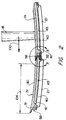
- Figure 2 is a cross-sectional view of an arcuate segment of the seal of the present invention taken along line 2-2 of Figure 1.
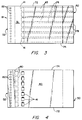
- Figure 3 is a plan view of the sealing surface of one of the segments of the present invention, showing the cooling passages and stand-off pedestals in phantom.
- Figure 4 is a plan view of the supply surface of one of the segments of the present invention, with the attachment hooks and feather seal channels omitted for clarity.
- Figure 5 is an enlarged cross-sectional view taken along line 5-5 of Figure 2.
- Figure 1 shows a portion of an axial flow gas turbine engine 10 having an axis of rotation 14 defined therethrough and incorporating a seal 11 embodying the invention.
- a portion of one rotor stage 12 of the turbine of the engine 10 is shown in Figure 1 and includes an annular working fluid flow path 13 disposed about the axis 14 for the combustion gases that are the working fluid of the engine.
- the turbine stage 12 has one stator assembly 15 axially upstream of the stage 12, and another stator assembly 16 axially downstream thereof.
- the stators 15, 16 are part of the static structure of the engine 10, and each stator assembly 15, 16 includes an outer case 17.
- the outer case 17 extends circumferentially around the flow path 13 of working fluid.
- the turbine stage 12 has a plurality of rotor blades, which are represented by the single rotor blade 18 in Figure 1, that extend radially outward relative to the axis 14 across the flow path 13 into close proximity with the outer case 17.
- An outer air seal 11 made up of a plurality of arcuate seal segments (represented by the single seal segment 19 in Figure 1) extends about the axis 14 to radially bound the annular flow path 13, and the seal 11 circumscribes the tips of the rotor blades 18.
- the outer air seal 11 is spaced radially inwardly from the outer case 17 leaving a circumferentially extending cavity 20 therebetween.
- the cavity 20 is in flow communication with a source of cooling air (not shown) and for cooling the segments 19 of the seal 11 as discussed below.
- Each arcuate seal segment 19 has an upstream attachment hook 21 and a downstream attachment hook 22 to engage upstream and downstream supports 23, 24, respectively, which extend inwardly from the outer case 17.
- the supports 23, 24 are attached to the outer case 17 to support and position the outer air seal 11 about the rotor blades 18.
- Each support 23, 24 may be segmented to reduce the hoop strength of the support 23, 24.
- a first flow path 25 for cooling air extends inwardly of the outer case 17.
- the cooling air flow path 25 is bounded by the outer case 17 and extends through the engine outwardly of the flow path 13 of the working fluid.
- the cooling air flow path extends into the cavity 20 between the outer air seal 11 and the outer case 17.
- Each seal segment 19 of the outer air seal 11 has a leading edge 26 and a trailing edge 27.
- the leading edge 26 is in spaced relation to the adjacent stator assembly 15 leaving a circumferentially extending cavity 28 therebetween.
- the cavity 28 forms a second cooling air flow path which extends axially and circumferentially beneath the leading edge region.
- the trailing edge 27 is in spaced relation to adjacent stator assembly 16 leaving an annular cavity 29 therebetween which forms a third cooling air flow path.
- each seal segment 19 has a metallic base 30 that has an arcuate sealing surface 31 that extends circumferentially about the axis 14 and the flow path 13. Each seal segment 19 is spaced radially outward from the blades 18, and the blades 18 rotate past the segments 19 in a first direction 100.
- the metallic base is integral with the hooks 21, 22.
- Adjacent seal segments 19 are spaced circumferentially from each other leaving an inter-segment gap 32 therebetween to allow for thermal expansion of the segments 19.
- the inter-segment gap 32 varies in size under various operative conditions of the engine 10.
- the inter-segment gap 32 terminates at a film slot 33 at the sealing surface 31.
- the segments 19 of the outer air seal 11 absorb heat from the working fluid. Since the metallic base 30 is generally made of a material that has relatively low creep strength at the temperature of the working fluid 13, each of the segments 19 must be cooled to maintain the temperature of the metallic base 30 well below the temperature of the working fluid 13.
- each blade 18 extends radially outward relative to the axis 14 and terminates at a blade tip 48.
- the tip 48 of each 18 blade is in spaced relation to the annular seal 11, and the sealing surface 31 of each segment 19 faces the turbine blades 18 and the working fluid flow path 13.
- a portion of the sealing surface 31 of each segment 19 radially outward from the blade tip 48 preferably includes a coating of an abradable material, and another portion of the sealing surface 31 at the leading and trailing edges 26, 27 preferably includes a coating of a thermal barrier material.
- abradable and thermal barrier materials are well known in the art, and therefore are not detailed further in this disclosure.
- a coolant supply surface 40 that is substantially parallel to, but offset from, the sealing surface 31.
- the coolant supply surface 40 has a plurality of cooling air inlet orifices 41 extending therethrough. These orifices 41 are sized to meter the flow of cooling air therethrough based on the supply pressure of the cooling air and the desired heat transfer from the seal segments 19.
- each seal segment 19 has a first end 50 and a second end 52 opposite the first end 50.
- the arcuate sealing surface 31 has a radius of curvature equal to the distance 54 between the sealing surface 31 and the axis 14 as shown in Figure 1.
- Each segment 19 has a first end surface 56 extending along the entire first end 50 of the sealing surface 31, and a second end surface 58 extending along the entire second end 52.
- the first and second end surfaces 56, 58 extend from the sealing surface 31 to the supply surface 40, and each of the first and second end surfaces 56, 58 has a substantially planar perpendicular surface 60, 62 and a substantially planar canted surface 64, 66.
- each canted surface 64, 66 of each end surface 56, 58 intersect at an included angle ⁇ of between 100 degrees and 140 degrees, and each canted surface 64, 66 is canted in the first direction 100.
- the phrase "canted in the first direction" means that for a given reference point 68 on one of the canted surfaces 64, 66, any other reference point 70 on that canted surface 64, 66 which lies to the first direction (i.e. to the left in Figure 5) of the given reference point 68 is spaced from the sealing surface 31 a distance which is less than the distance of the given reference point from the sealing surface 31.
- each segment 19 has a first side surface 72 and a second side surface 74, and each of the side surfaces 72, 74 extends from the sealing surface 31 to the supply surface 40, and, as shown in Figure 3, from the first end surface 56 to the second end surface 58.
- the cooling passages 43 are located between the sealing surface 31, the supply surface 40, and the side surfaces 72, 74, and each of the cooling passages 43 is separated from adjacent cooling passages 43 by a wall 76 therebetween.
- Each cooling passage 43 intersects the first end surface 56 and terminates short of the second end surface 58.
- Each cooling passage 43 communicates with the supply surface 40 through at least one of the cooling orifices 41.
- the preferred embodiment is shown and described in terms of a segment having a plurality of passages 43, a single, wide passage having a plurality of columns or pedestals therein would also suffice, so long as the quantity and placement of the columns is sufficient to provide heat transfer from the sealing surface to the cooling air in the passage, and also sufficient to support the sealing surface against collapse into the passage in the event the blades 18 rub into the sealing surface 31.
- each of the orifices 41 is adjacent said second end surface 58 and each cooling passage 43 communicates with the first end surface 56 of the same segment 19 through at least one passage outlet 78.
- cooling air entering the orifices 41 must flow through the passages 43 in a second direction 102 which is opposite the direction 100 of rotation of the blades 18 (the first direction 100).
- each segment 19 includes a quantity of cooling air feed pockets 80 equal to the quantity of passage outlets 78 in the first end surface 56 of the same segment 19.
- the purpose of the feed pockets 80 is to receive and turn the cooling air flowing from the passages 43, and feed the cooling air flowing from the passage outlets 78 so that the cooling air flows into the adjacent inter-segment gap 32, as shown in Figure 5. Accordingly, each feed pocket 80 is aligned with one of the cooling passage outlets 78 of one of the adjacent segments 19.
- Protruding from at least one of the substantially planar canted surfaces 66 of each segment 19 are a plurality of stand-off pedestals 82.
- the pedestals 82 insure that a minimum flow area is maintained in the inter-segment gap 32 during all engine operating conditions.
- the pedestals 82 are integral with one of the substantially canted surfaces 66, and extend toward one of the substantially planar canted surfaces 64 of one of the adjacent segments 19.
- pedestals 82 are shown as being integral with the canted surface 64 of the second end surface 58, those skilled in the art will readily appreciate that the pedestals 82 could be integral with the canted surface 64 of the first end surface 56, or some of the pedestals 82 could be integral with the canted surface 64 of the first end surface 56 and other pedestals 82 could be integral with the canted surface 66 of the second end surface 58, the latter pedestals 82 being offset from the pedestals 82 of the canted surface 64 of the first end surface 56.
- the pedestals 82 of each segment 19 are preferably aligned in a row extending between the first side surface 72 and the second side surface 74 of each segment 19, as shown in Figure 4.
- the sealing surface 31 of each segment is radiused 84 where it joins the substantially planar canted surface 66 of the second end surface 58.
- This radius 84, or curvature 84 provides a smooth transition between substantially planar canted surface 66 of the second end surface 58 and the sealing surface 31 of the same segment 19.
- the radius of curvature of this transition 84 is not critical, but those skilled in the art will appreciate that during some engine operating conditions, the blades 18 are likely to rub into the sealing surface 31 of each segment 19.
- the segment tip 86 (where the second end of the sealing surface 31 meets the second end surface 58) may break off due to the small cross-sectional area of the segment at the second end 52 of the sealing surface 31.
- Each of the substantially planar perpendicular surfaces 60, 62 of each segment 19 includes a channel 88, 90 located between the first side surface 72 and the second side surface 74.
- the channels 88, 90 of each segment 19 are substantially parallel to the supply surface 40 thereof, as shown in Figure 5. (The channels have been omitted from Figures 3 and 4 for clarity purposes, since the purpose of those figures is to show other features of the segments 19.)
- Each channel 88, 90 is opposed to, and in spaced relation to, one of the channels 88, 90 of one of the adjacent segments 19, and an inter-segment feather seal 92 extends between each of the opposed channels 88, 90 to prevent direct communication of the cooling air between the supply surface 40 and the inter-segment gap 32.
- cooling air from the cavity 20 flows into the cooling air passages 43 through the metering orifices 41 located at the supply surface 40 of the seal segment 19.
- the cooling air then flows through the passages 43 in a direction 102 opposite the direction 100 of the rotation of the blades 18, thereby cooling the walls 76 and absorbing heat that has been conducted from the sealing surface 31 of the segment 19.
- the spent cooling air then exits the passages 43 through one of the discharge outlets 78 and collects in the feed pocket 80 aligned therewith.
- the cooling air is then directed into the inter-segment gap 32, where it flows out past the pedestals 82 to provide film cooling of the sealing surface 31.
- the film travels in the direction 100 of the rotation of the blades 18, and cools the sealing surface 31 adjacent the first end surface 56.
- the cooling air is used to cool the portion of the sealing surface 31 which is distant from first end surface 56 (i.e. the portion of the sealing surface 31 which is both cooled and protected by the film cooling).
- the sealing surface 31 distant from the first end surface 56 is cooled by conductive heat transfer to the cooling air at its coolest temperature, producing a higher conductive heat transfer rate than occurs between the cooling air and the sealing surface 31 adjacent the first end surface 56.
- the lower heat transfer rate adjacent the first end surface 56 is acceptable since the sealing surface is both cooled and shielded by the film of spent cooling air adjacent the first end surface 56 of the segment 19.
- the blade outer air seal 11 uses the inter-segment gap 32 to create a film slot 33 that inhibits working fluid 13 infiltration into the inter-segment gap 32 and eliminates the need for additional purge air. It uses spent convective cooling air to purge the inter-segment gap 32 and discharges the cooling air through the film slot 33 tangentially as a cooling air film to provide supplemental film cooling of the blade outer air seal.
- the "bow-wave" from the suction-side of the blade tip 48 assists in spreading the film across the sealing surface 31 of the segment 19.
- the boundary layer attachment of the higher density cooling film is enhanced by the centrifugal Grashof effect, and a high tangential velocity results from the combined effects of the cooling air film injection direction and blade wiping.
- the sealing surface 31 is subjected to a cooler boundary layer, and mixing with the working fluid flow path is attenuated by this buoyancy effect.
- the circumferential length 104 of the sealing surface 31 of each segment 19 is preferably chosen such that the cooling air film discharged from the inter-segment gap 32 and film slot 33 will travel from the first end surface 56 of a segment 19 to the second end surface 58 of the sealing surface 31 of that segment 19 prior to being forced downstream of the blade outer air seal 11 by the working fluid 13 of the engine 10.
- the film slot 33 configuration shields the inter-segment feather seal 92 from infiltration by the working fluid 13 of the engine 10. Since the feed pockets 80 prevent convective air supply blockage with in the event that thermal expansion or blade rub induces closure of the inter-segment gap 32, circumferential tolerances of the segments 19 of the present invention are less critical than those of the prior art.
- the invention provides an outer air seal that minimizes the need for cooling air while providing the cooling necessary to extend the useful life of the outer air seal, uses spent cooling air to purge the inter-segment gap, thereby reducing the need for secondary cooling air, and introduces the film cooling air into the working fluid of the engine at a trajectory that minimizes mixing between the cooling air and the working fluid.
Landscapes
- Engineering & Computer Science (AREA)
- Mechanical Engineering (AREA)
- General Engineering & Computer Science (AREA)
- Turbine Rotor Nozzle Sealing (AREA)
Applications Claiming Priority (2)
| Application Number | Priority Date | Filing Date | Title |
|---|---|---|---|
| US08/166,426 US5374161A (en) | 1993-12-13 | 1993-12-13 | Blade outer air seal cooling enhanced with inter-segment film slot |
| US166426 | 1993-12-13 |
Publications (2)
| Publication Number | Publication Date |
|---|---|
| EP0657625A1 true EP0657625A1 (de) | 1995-06-14 |
| EP0657625B1 EP0657625B1 (de) | 1998-04-01 |
Family
ID=22603259
Family Applications (1)
| Application Number | Title | Priority Date | Filing Date |
|---|---|---|---|
| EP94309249A Expired - Lifetime EP0657625B1 (de) | 1993-12-13 | 1994-12-12 | Dichtung in einer Gasturbine |
Country Status (4)
| Country | Link |
|---|---|
| US (1) | US5374161A (de) |
| EP (1) | EP0657625B1 (de) |
| JP (1) | JP3607331B2 (de) |
| DE (1) | DE69409332T2 (de) |
Cited By (1)
| Publication number | Priority date | Publication date | Assignee | Title |
|---|---|---|---|---|
| EP1519010A1 (de) * | 2003-09-25 | 2005-03-30 | Siemens Westinghouse Power Corporation | Äussere Luftabdichtungsanordnung |
Families Citing this family (61)
| Publication number | Priority date | Publication date | Assignee | Title |
|---|---|---|---|---|
| US5486090A (en) * | 1994-03-30 | 1996-01-23 | United Technologies Corporation | Turbine shroud segment with serpentine cooling channels |
| US5531457A (en) * | 1994-12-07 | 1996-07-02 | Pratt & Whitney Canada, Inc. | Gas turbine engine feather seal arrangement |
| US5538393A (en) * | 1995-01-31 | 1996-07-23 | United Technologies Corporation | Turbine shroud segment with serpentine cooling channels having a bend passage |
| JP3898225B2 (ja) * | 1995-09-29 | 2007-03-28 | シーメンス アクチエンゲゼルシヤフト | 間隙を密封するためのシール要素並びにガスタービン設備 |
| US5823741A (en) * | 1996-09-25 | 1998-10-20 | General Electric Co. | Cooling joint connection for abutting segments in a gas turbine engine |
| DE59710924D1 (de) * | 1997-09-15 | 2003-12-04 | Alstom Switzerland Ltd | Kühlvorrichtung für Gasturbinenkomponenten |
| GB9725623D0 (en) | 1997-12-03 | 2006-09-20 | Rolls Royce Plc | Improvements in or relating to a blade tip clearance system |
| GB9815611D0 (en) | 1998-07-18 | 1998-09-16 | Rolls Royce Plc | Improvements in or relating to turbine cooling |
| US6393331B1 (en) | 1998-12-16 | 2002-05-21 | United Technologies Corporation | Method of designing a turbine blade outer air seal |
| JP3999395B2 (ja) * | 1999-03-03 | 2007-10-31 | 三菱重工業株式会社 | ガスタービン分割環 |
| GB2356022B (en) * | 1999-11-02 | 2003-12-10 | Rolls Royce Plc | Gas turbine engines |
| DE19963371A1 (de) * | 1999-12-28 | 2001-07-12 | Alstom Power Schweiz Ag Baden | Gekühltes Hitzeschild |
| GB0029337D0 (en) * | 2000-12-01 | 2001-01-17 | Rolls Royce Plc | A seal segment for a turbine |
| JP2002213207A (ja) * | 2001-01-15 | 2002-07-31 | Mitsubishi Heavy Ind Ltd | ガスタービン分割環 |
| EP1245792A1 (de) * | 2001-03-30 | 2002-10-02 | Siemens Aktiengesellschaft | Gekühlter Mantelring für eine Turbine und Verfahren zur Herstellung eines Mantelrings |
| US6910854B2 (en) * | 2002-10-08 | 2005-06-28 | United Technologies Corporation | Leak resistant vane cluster |
| US7094029B2 (en) * | 2003-05-06 | 2006-08-22 | General Electric Company | Methods and apparatus for controlling gas turbine engine rotor tip clearances |
| DE102004037356B4 (de) * | 2004-07-30 | 2017-11-23 | Ansaldo Energia Ip Uk Limited | Wandstruktur zur Begrenzung eines Heißgaspfads |
| US7217081B2 (en) * | 2004-10-15 | 2007-05-15 | Siemens Power Generation, Inc. | Cooling system for a seal for turbine vane shrouds |
| FR2877036B1 (fr) * | 2004-10-27 | 2006-12-22 | Snecma Moteurs Sa | Dispositif de lubrification d'un composant dans une turbomachine |
| US7520715B2 (en) * | 2005-07-19 | 2009-04-21 | Pratt & Whitney Canada Corp. | Turbine shroud segment transpiration cooling with individual cast inlet and outlet cavities |
| GB0523106D0 (en) * | 2005-11-12 | 2005-12-21 | Rolls Royce Plc | A cooliing arrangement |
| US7665955B2 (en) * | 2006-08-17 | 2010-02-23 | Siemens Energy, Inc. | Vortex cooled turbine blade outer air seal for a turbine engine |
| US7922444B2 (en) * | 2007-01-19 | 2011-04-12 | United Technologies Corporation | Chamfer rail pockets for turbine vane shrouds |
| US20090096174A1 (en) * | 2007-02-28 | 2009-04-16 | United Technologies Corporation | Blade outer air seal for a gas turbine engine |
| US20100021716A1 (en) * | 2007-06-19 | 2010-01-28 | Strock Christopher W | Thermal barrier system and bonding method |
| US7887929B2 (en) * | 2007-08-28 | 2011-02-15 | United Technologies Corporation | Oriented fiber ceramic matrix composite abradable thermal barrier coating |
| US20090110546A1 (en) * | 2007-10-29 | 2009-04-30 | United Technologies Corp. | Feather Seals and Gas Turbine Engine Systems Involving Such Seals |
| US8240981B2 (en) * | 2007-11-02 | 2012-08-14 | United Technologies Corporation | Turbine airfoil with platform cooling |
| US8177492B2 (en) * | 2008-03-04 | 2012-05-15 | United Technologies Corporation | Passage obstruction for improved inlet coolant filling |
| US7942188B2 (en) * | 2008-03-12 | 2011-05-17 | Vent-Tek Designs, Llc | Refractory metal core |
| US8317461B2 (en) * | 2008-08-27 | 2012-11-27 | United Technologies Corporation | Gas turbine engine component having dual flow passage cooling chamber formed by single core |
| GB2468848B (en) * | 2009-03-23 | 2011-10-26 | Rolls Royce Plc | An assembly for a turbomachine |
| US8740551B2 (en) * | 2009-08-18 | 2014-06-03 | Pratt & Whitney Canada Corp. | Blade outer air seal cooling |
| US8287234B1 (en) * | 2009-08-20 | 2012-10-16 | Florida Turbine Technologies, Inc. | Turbine inter-segment mate-face cooling design |
| US8727695B2 (en) * | 2009-12-09 | 2014-05-20 | Rolls-Royce Corporation | Chamfer-fillet gap for thermal management |
| US8585354B1 (en) * | 2010-01-19 | 2013-11-19 | Florida Turbine Technologies, Inc. | Turbine ring segment with riffle seal |
| US8727704B2 (en) | 2010-09-07 | 2014-05-20 | Siemens Energy, Inc. | Ring segment with serpentine cooling passages |
| RU2543101C2 (ru) * | 2010-11-29 | 2015-02-27 | Альстом Текнолоджи Лтд | Осевая газовая турбина |
| JP2012211527A (ja) | 2011-03-30 | 2012-11-01 | Mitsubishi Heavy Ind Ltd | ガスタービン |
| US9017012B2 (en) | 2011-10-26 | 2015-04-28 | Siemens Energy, Inc. | Ring segment with cooling fluid supply trench |
| US8992168B2 (en) * | 2011-10-28 | 2015-03-31 | United Technologies Corporation | Rotating vane seal with cooling air passages |
| WO2013110792A1 (de) * | 2012-01-26 | 2013-08-01 | Alstom Technology Ltd | Statorbauteil mit segmentiertem innenring für eine strömungsmaschine |
| JP5461636B2 (ja) * | 2012-08-24 | 2014-04-02 | 三菱重工業株式会社 | タービン分割環 |
| EP2961930B1 (de) | 2013-02-26 | 2020-05-27 | United Technologies Corporation | Kantenbehandlung für eine äussere laufschaufelluftdichtung |
| EP3042045A4 (de) * | 2013-09-06 | 2017-06-14 | United Technologies Corporation | Geneigte boas-intersegment-geometrie |
| US10221767B2 (en) | 2014-09-02 | 2019-03-05 | United Technologies Corporation | Actively cooled blade outer air seal |
| US10443423B2 (en) | 2014-09-22 | 2019-10-15 | United Technologies Corporation | Gas turbine engine blade outer air seal assembly |
| US10233844B2 (en) * | 2015-05-11 | 2019-03-19 | General Electric Company | System for thermally shielding a portion of a gas turbine shroud assembly |
| US10641120B2 (en) | 2015-07-24 | 2020-05-05 | Rolls-Royce Corporation | Seal segment for a gas turbine engine |
| RU2706211C2 (ru) * | 2016-01-25 | 2019-11-14 | Ансалдо Энерджиа Свитзерлэнд Аг | Охлаждаемая стенка компонента турбины и способ охлаждения этой стенки |
| US11156117B2 (en) * | 2016-04-25 | 2021-10-26 | Raytheon Technologies Corporation | Seal arc segment with sloped circumferential sides |
| US10697464B2 (en) * | 2016-07-29 | 2020-06-30 | Raytheon Technologies Corporation | Abradable material |
| US20180230839A1 (en) * | 2017-02-14 | 2018-08-16 | General Electric Company | Turbine engine shroud assembly |
| GB2559804A (en) * | 2017-02-21 | 2018-08-22 | Siemens Ag | Heatshield for a gas turbine |
| US10815807B2 (en) * | 2018-05-31 | 2020-10-27 | General Electric Company | Shroud and seal for gas turbine engine |
| US10794206B2 (en) | 2018-09-05 | 2020-10-06 | Raytheon Technologies Corporation | CMC BOAS intersegment seal |
| US20200072070A1 (en) * | 2018-09-05 | 2020-03-05 | United Technologies Corporation | Unified boas support and vane platform |
| US11359505B2 (en) * | 2019-05-04 | 2022-06-14 | Raytheon Technologies Corporation | Nesting CMC components |
| US11255208B2 (en) * | 2019-05-15 | 2022-02-22 | Raytheon Technologies Corporation | Feather seal for CMC BOAS |
| US11384654B2 (en) | 2019-11-18 | 2022-07-12 | Raytheon Technologies Corporation | Mateface for blade outer air seals in a gas turbine engine |
Citations (4)
| Publication number | Priority date | Publication date | Assignee | Title |
|---|---|---|---|---|
| GB1177410A (en) * | 1966-11-02 | 1970-01-14 | Gen Electric | Improvements in Gas Turbine Engine Turbine Rotor Shrouds |
| US3990807A (en) * | 1974-12-23 | 1976-11-09 | United Technologies Corporation | Thermal response shroud for rotating body |
| GB2166805A (en) * | 1984-11-13 | 1986-05-14 | United Technologies Corp | Coolable outer air seal assembly for a gas turbine engine |
| EP0516322A1 (de) * | 1991-05-20 | 1992-12-02 | General Electric Company | Kühlung für einen Gasturbinen-Statorring |
Family Cites Families (4)
| Publication number | Priority date | Publication date | Assignee | Title |
|---|---|---|---|---|
| CH525419A (de) * | 1970-12-18 | 1972-07-15 | Bbc Sulzer Turbomaschinen | Dichtungsvorrichtung für Turbomaschinen |
| GB2125111B (en) * | 1982-03-23 | 1985-06-05 | Rolls Royce | Shroud assembly for a gas turbine engine |
| US4642024A (en) * | 1984-12-05 | 1987-02-10 | United Technologies Corporation | Coolable stator assembly for a rotary machine |
| JPH03213602A (ja) * | 1990-01-08 | 1991-09-19 | General Electric Co <Ge> | ガスタービンエンジンの当接セグメントを連結する自己冷却式ジョイント連結構造 |
-
1993
- 1993-12-13 US US08/166,426 patent/US5374161A/en not_active Expired - Lifetime
-
1994
- 1994-12-12 DE DE69409332T patent/DE69409332T2/de not_active Expired - Lifetime
- 1994-12-12 EP EP94309249A patent/EP0657625B1/de not_active Expired - Lifetime
- 1994-12-13 JP JP30857094A patent/JP3607331B2/ja not_active Expired - Fee Related
Patent Citations (4)
| Publication number | Priority date | Publication date | Assignee | Title |
|---|---|---|---|---|
| GB1177410A (en) * | 1966-11-02 | 1970-01-14 | Gen Electric | Improvements in Gas Turbine Engine Turbine Rotor Shrouds |
| US3990807A (en) * | 1974-12-23 | 1976-11-09 | United Technologies Corporation | Thermal response shroud for rotating body |
| GB2166805A (en) * | 1984-11-13 | 1986-05-14 | United Technologies Corp | Coolable outer air seal assembly for a gas turbine engine |
| EP0516322A1 (de) * | 1991-05-20 | 1992-12-02 | General Electric Company | Kühlung für einen Gasturbinen-Statorring |
Cited By (1)
| Publication number | Priority date | Publication date | Assignee | Title |
|---|---|---|---|---|
| EP1519010A1 (de) * | 2003-09-25 | 2005-03-30 | Siemens Westinghouse Power Corporation | Äussere Luftabdichtungsanordnung |
Also Published As
| Publication number | Publication date |
|---|---|
| EP0657625B1 (de) | 1998-04-01 |
| DE69409332T2 (de) | 1998-10-29 |
| DE69409332D1 (de) | 1998-05-07 |
| JPH07233735A (ja) | 1995-09-05 |
| US5374161A (en) | 1994-12-20 |
| JP3607331B2 (ja) | 2005-01-05 |
Similar Documents
| Publication | Publication Date | Title |
|---|---|---|
| EP0657625B1 (de) | Dichtung in einer Gasturbine | |
| US5649806A (en) | Enhanced film cooling slot for turbine blade outer air seals | |
| US5375973A (en) | Turbine blade outer air seal with optimized cooling | |
| EP0808413B1 (de) | Konfiguration der gebogenen abschnitte von serpentinenförmigen kühlkanälen in turbinen | |
| US5486090A (en) | Turbine shroud segment with serpentine cooling channels | |
| EP0357984B1 (de) | Gasturbine mit einem gekühlten Leitschaufeldeckring | |
| EP0670953B1 (de) | Struktur für eine gekühlte schaufel | |
| CA2207033C (en) | Gas turbine engine feather seal arrangement | |
| CA2198225C (en) | Gas turbine blade with cooled platform | |
| US6481959B1 (en) | Gas turbine disk cavity ingestion inhibitor | |
| US4721433A (en) | Coolable stator structure for a gas turbine engine | |
| US4688988A (en) | Coolable stator assembly for a gas turbine engine | |
| AU2005284134B2 (en) | Turbine engine vane with fluid cooled shroud | |
| US4702670A (en) | Gas turbine engines | |
| US8858162B2 (en) | Labyrinth seal | |
| CA2367570C (en) | Split ring for gas turbine casing | |
| EP0789806A1 (de) | Gasturbinenschaufel mit gekühlter schaufelplattform | |
| US20100251687A1 (en) | Gas turbine: seal between adjacent can annular combustors | |
| EP0682741A1 (de) | Äussere luftabdichtung für ein gasturbinentriebwerk. | |
| US7665955B2 (en) | Vortex cooled turbine blade outer air seal for a turbine engine | |
| EP0694677B1 (de) | Schaufelspitzendichtungsring für eine Gasturbine | |
| CN111433438B (zh) | 用于燃气涡轮发动机的隔热罩 | |
| GB2161220A (en) | Gas turbine stator vane assembly |
Legal Events
| Date | Code | Title | Description |
|---|---|---|---|
| PUAI | Public reference made under article 153(3) epc to a published international application that has entered the european phase |
Free format text: ORIGINAL CODE: 0009012 |
|
| AK | Designated contracting states |
Kind code of ref document: A1 Designated state(s): DE FR GB |
|
| 17P | Request for examination filed |
Effective date: 19951007 |
|
| 17Q | First examination report despatched |
Effective date: 19960627 |
|
| GRAG | Despatch of communication of intention to grant |
Free format text: ORIGINAL CODE: EPIDOS AGRA |
|
| GRAG | Despatch of communication of intention to grant |
Free format text: ORIGINAL CODE: EPIDOS AGRA |
|
| GRAH | Despatch of communication of intention to grant a patent |
Free format text: ORIGINAL CODE: EPIDOS IGRA |
|
| GRAH | Despatch of communication of intention to grant a patent |
Free format text: ORIGINAL CODE: EPIDOS IGRA |
|
| GRAA | (expected) grant |
Free format text: ORIGINAL CODE: 0009210 |
|
| AK | Designated contracting states |
Kind code of ref document: B1 Designated state(s): DE FR GB |
|
| ET | Fr: translation filed | ||
| REF | Corresponds to: |
Ref document number: 69409332 Country of ref document: DE Date of ref document: 19980507 |
|
| PLBE | No opposition filed within time limit |
Free format text: ORIGINAL CODE: 0009261 |
|
| STAA | Information on the status of an ep patent application or granted ep patent |
Free format text: STATUS: NO OPPOSITION FILED WITHIN TIME LIMIT |
|
| 26N | No opposition filed | ||
| REG | Reference to a national code |
Ref country code: GB Ref legal event code: IF02 |
|
| PGFP | Annual fee paid to national office [announced via postgrant information from national office to epo] |
Ref country code: FR Payment date: 20081205 Year of fee payment: 15 |
|
| REG | Reference to a national code |
Ref country code: FR Ref legal event code: ST Effective date: 20100831 |
|
| PG25 | Lapsed in a contracting state [announced via postgrant information from national office to epo] |
Ref country code: FR Free format text: LAPSE BECAUSE OF NON-PAYMENT OF DUE FEES Effective date: 20091231 |
|
| PGFP | Annual fee paid to national office [announced via postgrant information from national office to epo] |
Ref country code: DE Payment date: 20121205 Year of fee payment: 19 |
|
| PGFP | Annual fee paid to national office [announced via postgrant information from national office to epo] |
Ref country code: GB Payment date: 20121212 Year of fee payment: 19 |
|
| REG | Reference to a national code |
Ref country code: DE Ref legal event code: R119 Ref document number: 69409332 Country of ref document: DE |
|
| GBPC | Gb: european patent ceased through non-payment of renewal fee |
Effective date: 20131212 |
|
| REG | Reference to a national code |
Ref country code: DE Ref legal event code: R119 Ref document number: 69409332 Country of ref document: DE Effective date: 20140701 |
|
| PG25 | Lapsed in a contracting state [announced via postgrant information from national office to epo] |
Ref country code: DE Free format text: LAPSE BECAUSE OF NON-PAYMENT OF DUE FEES Effective date: 20140701 |
|
| PG25 | Lapsed in a contracting state [announced via postgrant information from national office to epo] |
Ref country code: GB Free format text: LAPSE BECAUSE OF NON-PAYMENT OF DUE FEES Effective date: 20131212 |