EP0657644A2 - Dispositif d'injection de combustible pour moteurs à combustion interne - Google Patents
Dispositif d'injection de combustible pour moteurs à combustion interne Download PDFInfo
- Publication number
- EP0657644A2 EP0657644A2 EP94113012A EP94113012A EP0657644A2 EP 0657644 A2 EP0657644 A2 EP 0657644A2 EP 94113012 A EP94113012 A EP 94113012A EP 94113012 A EP94113012 A EP 94113012A EP 0657644 A2 EP0657644 A2 EP 0657644A2
- Authority
- EP
- European Patent Office
- Prior art keywords
- valve
- pressure
- injection device
- fuel injection
- sealing surface
- Prior art date
- Legal status (The legal status is an assumption and is not a legal conclusion. Google has not performed a legal analysis and makes no representation as to the accuracy of the status listed.)
- Granted
Links
Images
Classifications
-
- F—MECHANICAL ENGINEERING; LIGHTING; HEATING; WEAPONS; BLASTING
- F02—COMBUSTION ENGINES; HOT-GAS OR COMBUSTION-PRODUCT ENGINE PLANTS
- F02M—SUPPLYING COMBUSTION ENGINES IN GENERAL WITH COMBUSTIBLE MIXTURES OR CONSTITUENTS THEREOF
- F02M63/00—Other fuel-injection apparatus having pertinent characteristics not provided for in groups F02M39/00 - F02M57/00 or F02M67/00; Details, component parts, or accessories of fuel-injection apparatus, not provided for in, or of interest apart from, the apparatus of groups F02M39/00 - F02M61/00 or F02M67/00; Combination of fuel pump with other devices, e.g. lubricating oil pump
- F02M63/0003—Fuel-injection apparatus having a cyclically-operated valve for connecting a pressure source, e.g. constant pressure pump or accumulator, to an injection valve held closed mechanically, e.g. by springs, and automatically opened by fuel pressure
- F02M63/0007—Fuel-injection apparatus having a cyclically-operated valve for connecting a pressure source, e.g. constant pressure pump or accumulator, to an injection valve held closed mechanically, e.g. by springs, and automatically opened by fuel pressure using electrically actuated valves
-
- F—MECHANICAL ENGINEERING; LIGHTING; HEATING; WEAPONS; BLASTING
- F02—COMBUSTION ENGINES; HOT-GAS OR COMBUSTION-PRODUCT ENGINE PLANTS
- F02B—INTERNAL-COMBUSTION PISTON ENGINES; COMBUSTION ENGINES IN GENERAL
- F02B3/00—Engines characterised by air compression and subsequent fuel addition
- F02B3/06—Engines characterised by air compression and subsequent fuel addition with compression ignition
Definitions
- the invention is based on a fuel injection device for internal combustion engines according to the preamble of claim 1.
- a high-pressure fuel pump delivers fuel from a low-pressure chamber into a high-pressure collection chamber, which is connected via high-pressure lines to the individual injection valves projecting into the combustion chamber of the internal combustion engine to be supplied, this common pressure storage system being kept at a certain pressure by a pressure control device.
- an electrically controlled control valve is inserted into the high-pressure lines, which controls the opening and closing of the high-pressure fuel injection at the injection valve.
- the control valves on the injection valves are designed as solenoid valves, which open the connection of the high-pressure line to the injection valve at the start of injection and close it again at the end of injection.
- the control valves on the known fuel injection devices however, have the disadvantage that it with them it is not possible to shape the injection course at the injection valve.
- the main problem here is that the high fuel pressure applied to the injection valve cannot be released quickly enough, which can result in inaccuracies in the control at the end of the injection.
- the fuel injection device according to the invention with the characterizing features of claim 1 has the advantage that the end of injection can be safely controlled by means of a relief valve upstream of the relief valve.
- This return suction collar removes fuel from the pressure line to the injection valve during the closing movement of the control valve member, so that a rapid pressure drop at the injection end is ensured there.
- Another advantage is achieved by the arrangement in the pressure chamber of an annular shoulder acting in the opening direction of the valve for opening the connection between the high-pressure line and the injection valve, by means of which a safety function can be integrated into the control valve.
- This ring shoulder is designed so that when a predetermined maximum pressure in the high-pressure line and in the pressure chamber is exceeded, the opening cross-section to the ring space is released to a small extent, which is so small that the opening cross-section does not control the valve seat controlling the connection of the ring space to a relief chamber is completely closed, so that the excess fuel pressure from the annular space relaxes in the relief space and further into a return line to the low-pressure fuel space.
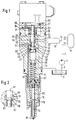
- FIG. 1 shows a schematic illustration of the fuel injection device with a longitudinal section through the control valve and the injection valve
- FIG. 2 shows an enlarged section of the control valve of FIG. 1, in which the arrangement of an additional annular shoulder on the valve member is shown.
- a high-pressure fuel pump 1 is connected on the suction side via a fuel supply line 3 to a fuel-filled low-pressure chamber 5 and on the pressure side via a delivery line 7 to a high-pressure collecting chamber 9.
- High-pressure lines 13 lead from the high-pressure plenum 9 to the individual injection valves 15 projecting into the combustion chamber of the internal combustion engine to be supplied, with an electric control valve 17 on each injection valve 15 in the respective one to control the injection process High pressure line 13 is used.
- a further pressure storage space 19 is provided in each high-pressure line 13 between the high-pressure collecting space 9 and the control valve 17, the dimensioning of which allows the injection course at the injection valve to be shaped.
- the control valve 17 is designed as a 3/2 way valve, the piston-shaped valve member 21 of which is actuated by an electric actuating magnet 25 acting on its one end face.
- the actuating magnet 25 is fastened to the valve member via an anchor plate 27 by means of a screw 29 in an axial blind bore of the valve member 21 and counteracts a return spring clamped between the housing 23 and a spring plate 31, which is arranged in a spring chamber 35 of the control valve 17.
- the piston-shaped valve member 21 has two mutually facing valve sealing surfaces, of which a first conical valve sealing surface 37 interacts with a conical valve seat 39.
- This conical valve sealing surface 37 is formed by a conical cross-sectional reduction of a guide piston part 41, which slides sealingly in a guide bore 43 and projects into the spring chamber 35 with its end facing away from the conical valve sealing surface 37.
- the conical valve seat 39 is formed by a reduction in the diameter of the guide bore 43, the sealing being effected via the outside diameter on the valve seat 39 when the valve is closed.
- the second valve sealing surface is designed as a flat sealing surface 45 and interacts with a flat valve seat 47.
- the flat valve sealing surface 45 is arranged on an axial ring surface facing the conical valve sealing surface 37 of an annular web 49 delimiting the valve member 21 on the side facing away from the actuating magnet 25.
- the flat valve seat 47 is formed by a ring shoulder on the guide bore 43 designed as a stepped bore.
- the Ring web 49 On the side bearing the flat sealing surface 45 the Ring web 49 to a first ring groove 51, which on the other hand is limited by a suction collar 53.
- This suckback collar 53 has only a slightly smaller outside diameter than the guide bore 43 designed as a stepped bore in this area and thus forms on its circumferential surface a throttle section 55 connected upstream of the flat seat valve, which opens into an annular space 57 on the side facing away from the first annular groove 51 the arrangement of a second annular groove 59 on the valve member 21 between the conical valve sealing surface 37 and the suction collar 53 is formed in the guide bore 43 and from which a pressure line 61 leads to the injection valve 15.
- the throttle 55 can also be formed by a small difference in diameter between the suction collar 53 and the guide piston part 41 with the same diameter of the guide bore 43 in these areas, the diameter of the guide piston part 41 then being about 5 to 30 ⁇ m larger than the diameter of the suction collar 53, so that there is a corresponding throttle ring gap on the throttle 55.
- a pressure chamber 63 adjoins the larger diameter of the conical valve sealing surface 37, into which the high-pressure line 13 opens.
- the ring web 49 protrudes with its end facing away from the flat valve seat 47 into a relief chamber 65 which continues axially in the direction facing away from the actuating magnet 25 into a spring chamber 67 of the injection valve 15, in which a valve spring 71 acting on a valve member 69 of the injection valve 15 in the closing direction is arranged and from which a return line 73 leads into the low-pressure chamber 5.
- the valve member 69 of the injection valve 15 is provided in a known manner with a conical pressure shoulder 75 which projects into a pressure chamber 77 connected to the pressure line 61 in such a way that the pressure in the pressure chamber 77 acts on the valve member 69 in the opening direction.
- An injection channel 79 also leads from the pressure chamber 77 along the valve member 69 to one or more of the Sealing surface at the tip of the valve member 69 controlled injection openings 81 of the injection valve 15 in the combustion chamber, not shown, of the internal combustion engine to be supplied.
- the spring chamber 35 of the control valve 17 is connected to the return line 73 via a connecting bore 83, so that the end faces of the valve member 21 are pressure-balanced.
- the stroke movement of the valve member 21 is in each case limited by the contact of the valve sealing surfaces 37, 45 on one of the valve seats 39, 47.
- the fuel injection device according to the invention works in the following way.
- the high-pressure fuel pump 1 conveys the fuel from the low-pressure chamber 5 into the high-pressure collection chamber 9 and thus builds up a high-pressure fuel in the latter. This high fuel pressure continues via the high-pressure lines 13 into the pressure chamber 63 of the individual control valves 17 on the injection valves 15 and also fills the respective pressure storage spaces 19.
- the actuating magnet 25 on the control valve 17 is de-energized, so that the return spring 33 holds the valve member 21 via the spring plate 31 with the conical valve sealing surface 37 in contact with the conical valve seat 39, so that the connection between the high pressure fuel chamber 63 and the annular chamber 57 permanently connected to the pressure line 61 to the injection valve 15 is closed and the connection from the annular space 57 into the relief space 65 is open.
- the actuating magnet 25 is energized and displaces the valve member 21 of the control valve 17 against the restoring force of the spring 33 until its flat valve sealing surface 45 abuts the flat valve seat 47.
- connection of the annular space 57 to the relief space 65 is closed and opened to the pressure line 61, so that the high fuel pressure is now from the pressure chamber 63 via the annular space 57 and the pressure line 61 propagates to the pressure chamber 77 of the injection valve 15 and there the injection at the injection openings 81 takes place in a known manner by lifting the valve member 69 from its valve seat. If the injection is to be ended, the actuating magnet 25 is again de-energized and the return spring 33 moves the valve member 21 back against the conical valve sealing surface 37 against the conical valve seat 39.
- the suction collar 53 releases a specific suction volume at the annular space 57 that the high-pressure fuel volume in the pressure line 61 relaxes, so that the fuel pressure in the pressure line 61 and on the injection valve 15 drops very quickly below the closing pressure of the injection valve 15 and the injection valve 15 closes safely.
- the further outflow of the fuel from the annular space 57 or the pressure line 61 now takes place via the throttle 55 on the suction collar 53, so that a certain residual pressure remains in the pressure line 61 until the following injection process.
- annular shoulder 91 formed by reducing the cross-section of the guide piston part 41, is provided on the valve member 21 in the region of the pressure chamber 63.
- This annular shoulder 91 serves as a relief or safety valve, which causes the conical valve seat 39 to open when the overpressure in the high-pressure line 13 is approximately 10%.
- the annular shoulder 91 is dimensioned such that it causes only a small opening stroke of the valve member 21, so that the flat seat valve does not close completely and the overpressure from the pressure chamber 63 can relax into the annular chamber 57 and further into the relief chamber 65.
Landscapes
- Engineering & Computer Science (AREA)
- Chemical & Material Sciences (AREA)
- Combustion & Propulsion (AREA)
- Mechanical Engineering (AREA)
- General Engineering & Computer Science (AREA)
- Fuel-Injection Apparatus (AREA)
Applications Claiming Priority (2)
| Application Number | Priority Date | Filing Date | Title |
|---|---|---|---|
| DE4341546A DE4341546A1 (de) | 1993-12-07 | 1993-12-07 | Kraftstoffeinspritzeinrichtung für Brennkraftmaschinen |
| DE4341546 | 1993-12-07 |
Publications (3)
| Publication Number | Publication Date |
|---|---|
| EP0657644A2 true EP0657644A2 (fr) | 1995-06-14 |
| EP0657644A3 EP0657644A3 (fr) | 1995-12-06 |
| EP0657644B1 EP0657644B1 (fr) | 1999-01-13 |
Family
ID=6504297
Family Applications (1)
| Application Number | Title | Priority Date | Filing Date |
|---|---|---|---|
| EP94113012A Expired - Lifetime EP0657644B1 (fr) | 1993-12-07 | 1994-08-20 | Dispositif d'injection de combustible pour moteurs à combustion interne |
Country Status (4)
| Country | Link |
|---|---|
| US (1) | US5538187A (fr) |
| EP (1) | EP0657644B1 (fr) |
| JP (1) | JP3742669B2 (fr) |
| DE (2) | DE4341546A1 (fr) |
Cited By (2)
| Publication number | Priority date | Publication date | Assignee | Title |
|---|---|---|---|---|
| DE19637186A1 (de) * | 1995-09-14 | 1997-03-20 | Avl Verbrennungskraft Messtech | Speichereinspritzsystem für eine Brennkraftmaschine |
| DE19907544A1 (de) * | 1999-02-22 | 2000-08-31 | Siemens Ag | Injektor für eine Einspritzanlage einer Brennkraftmaschine |
Families Citing this family (27)
| Publication number | Priority date | Publication date | Assignee | Title |
|---|---|---|---|---|
| DE19512730C1 (de) * | 1995-04-05 | 1996-08-29 | Mtu Friedrichshafen Gmbh | Kraftstoffeinspritzanlage für Brennkraftmaschine |
| DE19547877A1 (de) * | 1995-12-21 | 1997-06-26 | Bosch Gmbh Robert | Kraftstoffhochdruckspeichersystem für ein in Brennkraftmaschinen eingesetztes Kraftstoffeinspritzsystem |
| US5788154A (en) * | 1996-05-02 | 1998-08-04 | Caterpillar Inc. | Method of preventing cavitation in a fuel injector having a solenoid actuated control valve |
| GB9609382D0 (en) * | 1996-05-03 | 1996-07-10 | Lucas Ind Plc | Fuel injection system |
| JP3823391B2 (ja) * | 1996-08-31 | 2006-09-20 | いすゞ自動車株式会社 | エンジンの燃料噴射装置 |
| DE19712135C1 (de) | 1997-03-22 | 1998-08-13 | Mtu Friedrichshafen Gmbh | Kraftstoffeinspritzsystem für eine Brennkraftmaschine |
| US5860597A (en) * | 1997-03-24 | 1999-01-19 | Cummins Engine Company, Inc. | Injection rate shaping nozzle assembly for a fuel injector |
| DE19728111A1 (de) | 1997-07-02 | 1999-01-07 | Bosch Gmbh Robert | Kraftstoffeinspritzsystem |
| DE19732070C2 (de) * | 1997-07-25 | 2001-02-01 | Daimler Chrysler Ag | Direkteinspritzendes Kraftstoffeinspritzventil mit Magnetventilsteuerung für eine mehrzylindrige Brennkraftmaschine |
| EP0970305B1 (fr) * | 1997-12-23 | 2003-05-21 | Siemens Aktiengesellschaft | Soupape d'injection a vanne de controle |
| US5967413A (en) * | 1998-02-11 | 1999-10-19 | Caterpillar Inc. | Damped solenoid actuated valve and fuel injector using same |
| GB9812889D0 (en) * | 1998-06-15 | 1998-08-12 | Lucas Ind Plc | Fuel injector |
| US6029632A (en) * | 1998-07-21 | 2000-02-29 | Daimlerchrysler Ag | Fuel injector with magnetic valve control for a multicylinder internal combustion engine with direct fuel injection |
| US6113000A (en) * | 1998-08-27 | 2000-09-05 | Caterpillar Inc. | Hydraulically-actuated fuel injector with intensifier piston always exposed to high pressure actuation fluid inlet |
| DE19842067A1 (de) * | 1998-09-15 | 2000-03-16 | Daimler Chrysler Ag | Kraftstoffeinspritzanlage für eine Dieselbrennkraftmaschine |
| GB9823134D0 (en) * | 1998-10-23 | 1998-12-16 | Lucas Ind Plc | Valve |
| DE19928846A1 (de) * | 1999-06-24 | 2001-03-08 | Bosch Gmbh Robert | Common-Rail-Injektor |
| DE19951554A1 (de) * | 1999-10-26 | 2001-05-10 | Bosch Gmbh Robert | Kraftstoffinjektor mit integrierter Durchflussbegrenzung |
| DE19963367B4 (de) * | 1999-12-28 | 2008-07-31 | Robert Bosch Gmbh | Common-Rail-Injektor |
| DE10001828A1 (de) | 2000-01-18 | 2001-07-19 | Fev Motorentech Gmbh | Direktgesteuerte Kraftstoffeinspritzeinrichtung für eine Kolbenbrennkraftmaschine |
| DE10065221B4 (de) * | 2000-12-27 | 2007-11-29 | Robert Bosch Gmbh | Direkt gesteuertes 2-Sitzventil für Kraftstoffeinspritzsysteme |
| US7278593B2 (en) * | 2002-09-25 | 2007-10-09 | Caterpillar Inc. | Common rail fuel injector |
| FI117349B (fi) * | 2002-08-02 | 2006-09-15 | Waertsilae Finland Oy | Polttoaineen syöttöjärjestelmä |
| DE10342698A1 (de) * | 2003-09-16 | 2005-04-28 | Bosch Gmbh Robert | Druckgesteuerter CR-Injektor |
| JP5043761B2 (ja) * | 2008-06-18 | 2012-10-10 | 本田技研工業株式会社 | 燃料噴射装置 |
| CN107524551B (zh) * | 2017-08-31 | 2020-01-31 | 重庆红江机械有限责任公司 | 一种带保压结构的微喷电控喷油器 |
| CN108150662A (zh) * | 2018-02-05 | 2018-06-12 | 潍坊力创电子科技有限公司 | 双阀门气体喷射阀 |
Family Cites Families (10)
| Publication number | Priority date | Publication date | Assignee | Title |
|---|---|---|---|---|
| AU444015B2 (en) * | 1968-11-15 | 1973-12-19 | Pritchard Edward | Improvements in or relating to pressure jet burner control systems |
| FR2145081A5 (fr) * | 1971-07-08 | 1973-02-16 | Peugeot & Renault | |
| GB2045347B (en) * | 1979-02-24 | 1983-04-20 | Huber Motorenbau Inst | I c engine fuel injection system |
| JPS5655769U (fr) * | 1979-10-05 | 1981-05-14 | ||
| JPS60206973A (ja) * | 1984-03-30 | 1985-10-18 | Nippon Denso Co Ltd | アキユ−ムレ−タ型燃料噴射ノズル |
| CH668621A5 (de) * | 1986-01-22 | 1989-01-13 | Dereco Dieselmotoren Forschung | Kraftstoffeinspritzanlage fuer eine brennkraftmaschine. |
| JPS62288366A (ja) * | 1986-06-06 | 1987-12-15 | Kubota Ltd | ディーゼルエンジンの燃料噴射装置への燃料供給方法 |
| US4951874A (en) * | 1988-09-01 | 1990-08-28 | Diesel Kiki Co., Ltd. | Unit fuel injector |
| JPH0286953A (ja) * | 1988-09-21 | 1990-03-27 | Kanesaka Gijutsu Kenkyusho:Kk | 燃料噴射弁 |
| US4948049A (en) * | 1989-02-24 | 1990-08-14 | Ail Corporation | Rate control in accumulator type fuel injectors |
-
1993
- 1993-12-07 DE DE4341546A patent/DE4341546A1/de not_active Withdrawn
-
1994
- 1994-08-20 EP EP94113012A patent/EP0657644B1/fr not_active Expired - Lifetime
- 1994-08-20 DE DE59407647T patent/DE59407647D1/de not_active Expired - Fee Related
- 1994-11-14 US US08/339,684 patent/US5538187A/en not_active Expired - Lifetime
- 1994-12-07 JP JP30395594A patent/JP3742669B2/ja not_active Expired - Fee Related
Cited By (3)
| Publication number | Priority date | Publication date | Assignee | Title |
|---|---|---|---|---|
| DE19637186A1 (de) * | 1995-09-14 | 1997-03-20 | Avl Verbrennungskraft Messtech | Speichereinspritzsystem für eine Brennkraftmaschine |
| DE19907544A1 (de) * | 1999-02-22 | 2000-08-31 | Siemens Ag | Injektor für eine Einspritzanlage einer Brennkraftmaschine |
| DE19907544C2 (de) * | 1999-02-22 | 2002-12-05 | Siemens Ag | Injektor für eine Einspritzanlage einer Brennkraftmaschine |
Also Published As
| Publication number | Publication date |
|---|---|
| US5538187A (en) | 1996-07-23 |
| JPH07189851A (ja) | 1995-07-28 |
| DE59407647D1 (de) | 1999-02-25 |
| EP0657644A3 (fr) | 1995-12-06 |
| DE4341546A1 (de) | 1995-06-08 |
| EP0657644B1 (fr) | 1999-01-13 |
| JP3742669B2 (ja) | 2006-02-08 |
Similar Documents
| Publication | Publication Date | Title |
|---|---|---|
| EP0657644B1 (fr) | Dispositif d'injection de combustible pour moteurs à combustion interne | |
| EP0960274B1 (fr) | Dispositif d'injection de carburant pour moteurs a combustion interne | |
| EP0657642B1 (fr) | Dispositif d'injection de combustible pour moteurs à combustion interne | |
| EP0657643B1 (fr) | Dispositif d'injection de combustible pour moteurs à combustion interne | |
| DE4414242A1 (de) | Kraftstoffeinspritzeinrichtung für Brennkraftmaschinen | |
| EP0807757A1 (fr) | Injecteur de combustible pour moteur à combustion interne | |
| DE19709794A1 (de) | Ventil zum Steuern von Flüssigkeiten | |
| DE4445980C2 (de) | Einspritzsystem | |
| EP1068445B1 (fr) | Dispositif d'injection de carburant pour moteurs a combustion interne | |
| DE4243665C2 (de) | Kraftstoffeinspritzeinrichtung, insbesondere Pumpedüse für Brennkraftmaschinen | |
| DE60215591T2 (de) | Kraftsoffeinspritzventil | |
| EP0050710A1 (fr) | Installation d'injection de carburant | |
| DE2750042A1 (de) | Kraftstoffeinspritzsystem | |
| DE4211651B4 (de) | Kraftstoffeinspritzeinrichtung, insbesondere Pumpedüse für Brennkraftmaschinen | |
| WO1999018349A1 (fr) | Soupape d'injection a commande directe, en particulier soupape d'injection de carburant | |
| EP1097303A2 (fr) | Dispositif d'injection de carburant | |
| EP1923564A2 (fr) | Injecteur de carburant | |
| EP1373714B1 (fr) | Soupape d'injection | |
| DE19954288A1 (de) | Kraftstoffeinspritzventil für Brennkraftmaschinen | |
| DE29814934U1 (de) | Kraftstoffeinspritzventil für Brennkraftmaschinen | |
| DE19747092B4 (de) | Durchflußbegrenzungsvorrichtung für Brennkraftmaschinen | |
| DE68913416T2 (de) | Hochdruck-Brennstoffeinspritzgerät für Motoren. | |
| EP1961953A1 (fr) | Soupape à plusieurs voies | |
| DE4410742A1 (de) | Kraftstoffpumpe | |
| DE10050599B4 (de) | Einspritzventil mit einem Pumpkolben |
Legal Events
| Date | Code | Title | Description |
|---|---|---|---|
| PUAI | Public reference made under article 153(3) epc to a published international application that has entered the european phase |
Free format text: ORIGINAL CODE: 0009012 |
|
| AK | Designated contracting states |
Kind code of ref document: A2 Designated state(s): DE FR GB IT |
|
| PUAL | Search report despatched |
Free format text: ORIGINAL CODE: 0009013 |
|
| AK | Designated contracting states |
Kind code of ref document: A3 Designated state(s): DE FR GB IT |
|
| 17P | Request for examination filed |
Effective date: 19960607 |
|
| 17Q | First examination report despatched |
Effective date: 19971007 |
|
| GRAG | Despatch of communication of intention to grant |
Free format text: ORIGINAL CODE: EPIDOS AGRA |
|
| GRAG | Despatch of communication of intention to grant |
Free format text: ORIGINAL CODE: EPIDOS AGRA |
|
| GRAH | Despatch of communication of intention to grant a patent |
Free format text: ORIGINAL CODE: EPIDOS IGRA |
|
| GRAH | Despatch of communication of intention to grant a patent |
Free format text: ORIGINAL CODE: EPIDOS IGRA |
|
| GRAA | (expected) grant |
Free format text: ORIGINAL CODE: 0009210 |
|
| AK | Designated contracting states |
Kind code of ref document: B1 Designated state(s): DE FR GB IT |
|
| REF | Corresponds to: |
Ref document number: 59407647 Country of ref document: DE Date of ref document: 19990225 |
|
| ET | Fr: translation filed | ||
| ITF | It: translation for a ep patent filed | ||
| GBT | Gb: translation of ep patent filed (gb section 77(6)(a)/1977) |
Effective date: 19990318 |
|
| PLBE | No opposition filed within time limit |
Free format text: ORIGINAL CODE: 0009261 |
|
| STAA | Information on the status of an ep patent application or granted ep patent |
Free format text: STATUS: NO OPPOSITION FILED WITHIN TIME LIMIT |
|
| 26N | No opposition filed | ||
| REG | Reference to a national code |
Ref country code: GB Ref legal event code: IF02 |
|
| PGFP | Annual fee paid to national office [announced via postgrant information from national office to epo] |
Ref country code: DE Payment date: 20071024 Year of fee payment: 14 |
|
| PGFP | Annual fee paid to national office [announced via postgrant information from national office to epo] |
Ref country code: IT Payment date: 20080826 Year of fee payment: 15 Ref country code: FR Payment date: 20080818 Year of fee payment: 15 |
|
| PGFP | Annual fee paid to national office [announced via postgrant information from national office to epo] |
Ref country code: GB Payment date: 20080822 Year of fee payment: 15 |
|
| PG25 | Lapsed in a contracting state [announced via postgrant information from national office to epo] |
Ref country code: DE Free format text: LAPSE BECAUSE OF NON-PAYMENT OF DUE FEES Effective date: 20090303 |
|
| GBPC | Gb: european patent ceased through non-payment of renewal fee |
Effective date: 20090820 |
|
| PG25 | Lapsed in a contracting state [announced via postgrant information from national office to epo] |
Ref country code: FR Free format text: LAPSE BECAUSE OF NON-PAYMENT OF DUE FEES Effective date: 20090831 |
|
| REG | Reference to a national code |
Ref country code: FR Ref legal event code: ST Effective date: 20100630 |
|
| PG25 | Lapsed in a contracting state [announced via postgrant information from national office to epo] |
Ref country code: GB Free format text: LAPSE BECAUSE OF NON-PAYMENT OF DUE FEES Effective date: 20090820 |
|
| PG25 | Lapsed in a contracting state [announced via postgrant information from national office to epo] |
Ref country code: IT Free format text: LAPSE BECAUSE OF NON-PAYMENT OF DUE FEES Effective date: 20090820 |