EP0807757A1 - Injecteur de combustible pour moteur à combustion interne - Google Patents
Injecteur de combustible pour moteur à combustion interne Download PDFInfo
- Publication number
- EP0807757A1 EP0807757A1 EP97112502A EP97112502A EP0807757A1 EP 0807757 A1 EP0807757 A1 EP 0807757A1 EP 97112502 A EP97112502 A EP 97112502A EP 97112502 A EP97112502 A EP 97112502A EP 0807757 A1 EP0807757 A1 EP 0807757A1
- Authority
- EP
- European Patent Office
- Prior art keywords
- injection valve
- fuel
- control
- pressure
- fuel injection
- Prior art date
- Legal status (The legal status is an assumption and is not a legal conclusion. Google has not performed a legal analysis and makes no representation as to the accuracy of the status listed.)
- Withdrawn
Links
Images
Classifications
-
- F—MECHANICAL ENGINEERING; LIGHTING; HEATING; WEAPONS; BLASTING
- F02—COMBUSTION ENGINES; HOT-GAS OR COMBUSTION-PRODUCT ENGINE PLANTS
- F02M—SUPPLYING COMBUSTION ENGINES IN GENERAL WITH COMBUSTIBLE MIXTURES OR CONSTITUENTS THEREOF
- F02M47/00—Fuel-injection apparatus operated cyclically with fuel-injection valves actuated by fluid pressure
- F02M47/02—Fuel-injection apparatus operated cyclically with fuel-injection valves actuated by fluid pressure of accumulator-injector type, i.e. having fuel pressure of accumulator tending to open, and fuel pressure in other chamber tending to close, injection valves and having means for periodically releasing that closing pressure
- F02M47/027—Electrically actuated valves draining the chamber to release the closing pressure
-
- F—MECHANICAL ENGINEERING; LIGHTING; HEATING; WEAPONS; BLASTING
- F02—COMBUSTION ENGINES; HOT-GAS OR COMBUSTION-PRODUCT ENGINE PLANTS
- F02M—SUPPLYING COMBUSTION ENGINES IN GENERAL WITH COMBUSTIBLE MIXTURES OR CONSTITUENTS THEREOF
- F02M45/00—Fuel-injection apparatus characterised by having a cyclic delivery of specific time/pressure or time/quantity relationship
-
- F—MECHANICAL ENGINEERING; LIGHTING; HEATING; WEAPONS; BLASTING
- F02—COMBUSTION ENGINES; HOT-GAS OR COMBUSTION-PRODUCT ENGINE PLANTS
- F02M—SUPPLYING COMBUSTION ENGINES IN GENERAL WITH COMBUSTIBLE MIXTURES OR CONSTITUENTS THEREOF
- F02M61/00—Fuel-injectors not provided for in groups F02M39/00 - F02M57/00 or F02M67/00
- F02M61/16—Details not provided for in, or of interest apart from, the apparatus of groups F02M61/02 - F02M61/14
- F02M61/20—Closing valves mechanically, e.g. arrangements of springs or weights or permanent magnets; Damping of valve lift
- F02M61/205—Means specially adapted for varying the spring tension or assisting the spring force to close the injection-valve, e.g. with damping of valve lift
-
- F—MECHANICAL ENGINEERING; LIGHTING; HEATING; WEAPONS; BLASTING
- F02—COMBUSTION ENGINES; HOT-GAS OR COMBUSTION-PRODUCT ENGINE PLANTS
- F02M—SUPPLYING COMBUSTION ENGINES IN GENERAL WITH COMBUSTIBLE MIXTURES OR CONSTITUENTS THEREOF
- F02M2200/00—Details of fuel-injection apparatus, not otherwise provided for
- F02M2200/30—Fuel-injection apparatus having mechanical parts, the movement of which is damped
- F02M2200/304—Fuel-injection apparatus having mechanical parts, the movement of which is damped using hydraulic means
-
- F—MECHANICAL ENGINEERING; LIGHTING; HEATING; WEAPONS; BLASTING
- F02—COMBUSTION ENGINES; HOT-GAS OR COMBUSTION-PRODUCT ENGINE PLANTS
- F02M—SUPPLYING COMBUSTION ENGINES IN GENERAL WITH COMBUSTIBLE MIXTURES OR CONSTITUENTS THEREOF
- F02M2547/00—Special features for fuel-injection valves actuated by fluid pressure
- F02M2547/001—Control chambers formed by movable sleeves
-
- F—MECHANICAL ENGINEERING; LIGHTING; HEATING; WEAPONS; BLASTING
- F02—COMBUSTION ENGINES; HOT-GAS OR COMBUSTION-PRODUCT ENGINE PLANTS
- F02M—SUPPLYING COMBUSTION ENGINES IN GENERAL WITH COMBUSTIBLE MIXTURES OR CONSTITUENTS THEREOF
- F02M63/00—Other fuel-injection apparatus having pertinent characteristics not provided for in groups F02M39/00 - F02M57/00 or F02M67/00; Details, component parts, or accessories of fuel-injection apparatus, not provided for in, or of interest apart from, the apparatus of groups F02M39/00 - F02M61/00 or F02M67/00; Combination of fuel pump with other devices, e.g. lubricating oil pump
- F02M63/0012—Valves
- F02M63/0031—Valves characterized by the type of valves, e.g. special valve member details, valve seat details, valve housing details
- F02M63/0054—Check valves
-
- Y—GENERAL TAGGING OF NEW TECHNOLOGICAL DEVELOPMENTS; GENERAL TAGGING OF CROSS-SECTIONAL TECHNOLOGIES SPANNING OVER SEVERAL SECTIONS OF THE IPC; TECHNICAL SUBJECTS COVERED BY FORMER USPC CROSS-REFERENCE ART COLLECTIONS [XRACs] AND DIGESTS
- Y10—TECHNICAL SUBJECTS COVERED BY FORMER USPC
- Y10T—TECHNICAL SUBJECTS COVERED BY FORMER US CLASSIFICATION
- Y10T137/00—Fluid handling
- Y10T137/8593—Systems
- Y10T137/86389—Programmer or timer
- Y10T137/86405—Repeating cycle
Definitions
- the invention relates to a fuel injection valve for intermittent fuel injection into the combustion chamber of an internal combustion engine.
- the invention solves the problem of creating a fuel injector which is extremely simple in terms of production and assembly technology.
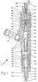
- the fuel injection valve 1 shows a fuel injection valve 1 in a position between two injection processes.
- the fuel injection valve 1 is connected via a high-pressure fuel connection 10 and via a fuel return connection 12 to a high-pressure delivery device for the fuel and via electrical connections 14 to an electronic control.
- the high-pressure conveyor and the electronic control are not shown in the drawing.
- the housing of the fuel injector 1 is designated 15. At the lower end is on the housing 15 as Retaining nut trained retaining part 16, a corresponding retaining nut 17 screwed on at the upper end.
- a nozzle body 18 is inserted in the holding part 16, the nozzle tip 19 of which protrudes from the holding part 16.
- the nozzle tip 19 is provided with a nozzle needle seat 20 and has a plurality of injection openings 21 in this area.
- an axially adjustable nozzle needle 24 forming an injection valve member is slidably guided in a needle guide bore 23.
- the injection openings 21 of the nozzle tip 19 can be closed by a lower end 25 of the nozzle needle 24.
- the housing 15 is provided with a central guide bore 29 in which a control device 3 for controlling the adjustment movement of the injection valve member or the nozzle needle 24 is arranged.
- the control device 3 is described in detail below with reference to FIG. 2.
- the fuel is conveyed by the high-pressure delivery device via the high-pressure fuel connection 10 and a first short fuel supply bore 31 into two high-pressure supply lines 32, 33 arranged in the housing 15 parallel to the guide bore 29.
- the upper high-pressure supply line 33 leads to the control device 3.
- the lower high-pressure supply line 32 is connected via a connecting bore 35 arranged obliquely in an intermediate plate 36 to a nozzle body bore 26 which opens into an annular space 27 in the nozzle body 18. From the annular space 27, the fuel reaches the nozzle needle seat 20 or the injection openings 21 via passages (not shown in detail).
- the intermediate plate 36 is positioned opposite the housing 15 via a pin 37 (it could also be two pins 37) and is arranged sealingly between the housing 15 and the nozzle body 18.
- a pin 37 it could also be two pins 37
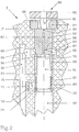
- One in a central bore 38 of the Intermediate plate 36 protruding upper part 39 of the nozzle needle 24 is operatively connected to an intermediate needle element 40, which on the other hand is connected to a control piston 50 of the control device 3 via a connecting rod 44.
- a nozzle needle spring 47 surrounding the connecting rod 44 is arranged pretensioned.
- the control device 3 has a control body 52 which is inserted into the guide bore 29 in a stationary manner.
- the control piston 50 is provided with an upper piston part 51 of reduced diameter.
- the upper piston part 51 projects into a sleeve 64 which is axially displaceable and closely sliding in the guide bore 29. Close sliding fits are also provided between the piston part 51 and the inner diameter of the sleeve 64.
- a spring 63 is arranged between a lower end face 65 of the sleeve 64 and a piston shoulder surface 53.
- the sleeve 64 is supported with a narrow annular sealing surface 66 on a lower end face 55 of the control body 52, which on the other hand is axially fixed in the guide bore 29 by a lock nut 54 screwed to the housing 15.
- control body 52 In the lower region of the control body 52 there is an annular space 69 in the housing 15, which is connected to the upper high-pressure supply line 33 via a transverse bore 68.
- the control body 52 has a circumferential annular groove 67 corresponding to the annular space 69.
- the control body 52 is provided with a connection bore 60 opening into a first control space 70, which is connected via an inlet throttle bore 58 to the circumferential annular groove 67 or to the annular space 69 and thus also to the high-pressure supply line 33.
- the connection bore 60 narrows into an outlet opening 59.
- the first control chamber 70 is delimited radially by the inner surface of the sleeve 64, axially by the lower end surface 55 of the control body 52 and an upper end surface 56 of the piston part 51.
- the control body 52 is installed in the guide bore 29 of the housing 15 in such a way that no significant leakage can take place. This will e.g. achieved with a press fit or a narrow sliding fit, but could also be realized by other fuel-tight connections, for example using suitable sealing rings.
- the control device 3 also has an electromagnetically actuated pilot valve 80, of which only one armature 82, which is firmly connected to a pilot valve stem 81, can be seen in FIG. In the position shown in FIG. 2, the outlet throttle bore 59 is held in the closed position via a flat valve seat 85. As can be seen from FIG. 1, in the de-energized state of an electromagnet 86, the pilot valve stem 81 is pressed downward into the position closing the valve flat seat 85 by the force of a compression spring 87. This force can be adjusted in size by means of an adjusting screw 88. To actuate the pilot valve 80 or to raise the pilot valve stem 81 from the flat valve seat 85, an excitation coil 83 of the electromagnet 86 assigned to the armature 82 receives control pulses from the electronic control via the electrical connections 14.
- the fuel emerging from the outlet opening 59 when the pilot valve stem 81 is raised is collected in a discharge space 89 and fed via a discharge bore 90 to the fuel return connection 12, which is installed together with the electromagnet 86 in the holding nut 17.
- the fuel accumulated by leaks in a space 91 below the control piston 50 also flows into the discharge space 89 via a relief bore 92. Part of the fuel is thus returned to the high-pressure delivery device practically without pressure.
- the space 91, the relief bore 92, the drain space 89 and the drain bore 90 form a so-called low-pressure part of the fuel injection valve 1.
- the armature 82 is attracted against the force of the spring 87, whereby the pilot valve 80 is opened.
- the outlet opening 59 of the control body 52 is thus opened.
- the pressure in the first control chamber 70 drops.
- the nozzle needle 24 is raised from the nozzle needle seat 20 by the fuel pressure prevailing in the annular space 27 and acting on the shoulder 28.
- the injection openings 21 are opened and the fuel is injected into the combustion chamber of the internal combustion engine in a manner known per se.
- the control piston 50 When the nozzle needle 24 is raised, the control piston 50 is also moved upward via the intermediate needle element 40 and the connecting rod 44.
- the volume of the second control chamber 74 becomes smaller, the pressure in the control chamber 74 increases under this pumping action.
- the sleeve 64 is pressed even more strongly into the sealing position with respect to the control body 52.
- the pressure in the second control chamber 74 which counteracts the opening movement of the injection valve member or the nozzle needle 24, is defined in a desired, controlled manner via the connecting bore 75 and the throttle 77, which lead to the high-pressure supply line 33. A desired, controlled opening of the injection valve is thereby achieved.
- the end of the injection process should take place as quickly as possible.
- the pilot valve 80 is brought into its closed position via the electromagnet 86. Since the outlet opening 59 is now closed again, the pressure in the first control chamber 70 increases, and the control piston 50 is moved downward by the force acting on the upper end face 56 of the piston part 51. The volume of the second control chamber 74 is increased, the fuel pressure in the second control chamber 74 drops. The sleeve 64 initially remains pressed onto the control body 52. When the fuel pressure in the second control chamber 74 drops, the sleeve 64 follows the piston movement; it should be mentioned that the spring 63 is biased relatively weakly, so that the pressure effect of the spring 63 is negligible compared to the fuel pressure forces.
- the spring 63 presses the sleeve 64 with the sealing surface 66 into the position radially delimiting the first control chamber 70.
Landscapes
- Engineering & Computer Science (AREA)
- Chemical & Material Sciences (AREA)
- Combustion & Propulsion (AREA)
- Mechanical Engineering (AREA)
- General Engineering & Computer Science (AREA)
- Physics & Mathematics (AREA)
- Fluid Mechanics (AREA)
- Fuel-Injection Apparatus (AREA)
Applications Claiming Priority (3)
| Application Number | Priority Date | Filing Date | Title |
|---|---|---|---|
| CH1782/94 | 1994-06-06 | ||
| CH178294 | 1994-06-06 | ||
| EP95107718A EP0686763B1 (fr) | 1994-06-06 | 1995-05-20 | Injecteur de combustible pour moteurs à combustion interne |
Related Parent Applications (2)
| Application Number | Title | Priority Date | Filing Date |
|---|---|---|---|
| EP95107718A Division EP0686763B1 (fr) | 1994-06-06 | 1995-05-20 | Injecteur de combustible pour moteurs à combustion interne |
| EP95107718.9 Division | 1995-05-20 |
Publications (1)
| Publication Number | Publication Date |
|---|---|
| EP0807757A1 true EP0807757A1 (fr) | 1997-11-19 |
Family
ID=4218485
Family Applications (2)
| Application Number | Title | Priority Date | Filing Date |
|---|---|---|---|
| EP97112502A Withdrawn EP0807757A1 (fr) | 1994-06-06 | 1995-05-20 | Injecteur de combustible pour moteur à combustion interne |
| EP95107718A Expired - Lifetime EP0686763B1 (fr) | 1994-06-06 | 1995-05-20 | Injecteur de combustible pour moteurs à combustion interne |
Family Applications After (1)
| Application Number | Title | Priority Date | Filing Date |
|---|---|---|---|
| EP95107718A Expired - Lifetime EP0686763B1 (fr) | 1994-06-06 | 1995-05-20 | Injecteur de combustible pour moteurs à combustion interne |
Country Status (5)
| Country | Link |
|---|---|
| US (2) | US5685483A (fr) |
| EP (2) | EP0807757A1 (fr) |
| JP (1) | JPH07332193A (fr) |
| AT (1) | ATE184078T1 (fr) |
| DE (1) | DE59506715D1 (fr) |
Cited By (1)
| Publication number | Priority date | Publication date | Assignee | Title |
|---|---|---|---|---|
| WO2002073023A1 (fr) * | 2001-03-12 | 2002-09-19 | Robert Bosch Gmbh | Injecteur |
Families Citing this family (49)
| Publication number | Priority date | Publication date | Assignee | Title |
|---|---|---|---|---|
| FI101738B (fi) * | 1996-01-30 | 1998-08-14 | Waertsilae Nsd Oy Ab | Ruiskutusventtiilijärjestely |
| GB9606803D0 (en) * | 1996-03-30 | 1996-06-05 | Lucas Ind Plc | Injection nozzle |
| DE19618468C1 (de) * | 1996-05-08 | 1997-04-30 | Siemens Ag | Einspritzventil |
| FR2752268B1 (fr) * | 1996-08-07 | 1998-09-18 | Froment Jean Louis | Dispositif d'amelioration de la dynamique d'injection de combustible pour les moteurs diesel equipes de pompes d'injection a debit pulse |
| GB9624513D0 (en) * | 1996-11-26 | 1997-01-15 | Lucas Ind Plc | Injector |
| GB9700491D0 (en) * | 1997-01-11 | 1997-02-26 | Lucas Ind Plc | Injector |
| DE19744518A1 (de) * | 1997-10-09 | 1999-04-15 | Bosch Gmbh Robert | Kraftstoffeinspritzventil für Brennkraftmaschinen |
| US6237570B1 (en) * | 1997-10-09 | 2001-05-29 | Denso Corporation | Accumulator fuel injection apparatus |
| DE19826791A1 (de) * | 1998-06-16 | 1999-12-23 | Bosch Gmbh Robert | Ventilsteuereinheit für ein Kraftstoffeinspritzventil |
| JP2002529654A (ja) * | 1998-11-10 | 2002-09-10 | ガンサー−ハイドロマグ アーゲー | 内燃機関用燃料噴射バルブ |
| DE19936668A1 (de) * | 1999-08-04 | 2001-02-22 | Bosch Gmbh Robert | Common-Rail-Injektor |
| EP1081372B1 (fr) * | 1999-08-31 | 2004-10-13 | Denso Corporation | Dispositif d'injection de carburant |
| DE19949526A1 (de) * | 1999-10-14 | 2001-04-19 | Bosch Gmbh Robert | Injektor für ein Common-Rail-Kraftstoffeinspritzsystem für Brennkraftmaschinen mit teilweisem Kraftausgleich der Düsennadel |
| US6293254B1 (en) * | 2000-01-07 | 2001-09-25 | Cummins Engine Company, Inc. | Fuel injector with floating sleeve control chamber |
| EP1118765A3 (fr) * | 2000-01-19 | 2003-11-19 | CRT Common Rail Technologies AG | Injecteur de combustible pour moteur à combustion interne |
| US6283441B1 (en) | 2000-02-10 | 2001-09-04 | Caterpillar Inc. | Pilot actuator and spool valve assembly |
| DE10006915B4 (de) * | 2000-02-16 | 2004-02-05 | Siemens Ag | Drosselbohrungsanordnung |
| DE10015740C2 (de) * | 2000-03-29 | 2003-12-18 | Siemens Ag | Einspritzventil für die Einspritzung von Kraftstoff in eine Verbrennungskraftmaschine |
| JP3551898B2 (ja) * | 2000-06-15 | 2004-08-11 | トヨタ自動車株式会社 | 燃料噴射弁 |
| DE10031576C2 (de) * | 2000-06-29 | 2002-07-11 | Bosch Gmbh Robert | Druckgesteuerter Injektor zum Einspritzen von Kraftstoff |
| US6412473B1 (en) | 2000-06-29 | 2002-07-02 | Caterpillar Inc. | Rate shaped fluid driven piston assembly and fuel injector using same |
| DE10032517A1 (de) * | 2000-07-05 | 2002-01-24 | Bosch Gmbh Robert | Injektor mit Steuerteilführung |
| AU2001295357A1 (en) | 2000-11-17 | 2002-05-27 | Crt Common Rail Technologies Ag | Fuel-injection valve for internal combustion engines |
| DE10100390A1 (de) * | 2001-01-05 | 2002-07-25 | Bosch Gmbh Robert | Einspritzventil |
| WO2002086309A1 (fr) * | 2001-04-24 | 2002-10-31 | Crt Common Rail Technologies Ag | Soupape d'injection de carburant destinee a des machines a combustion interne |
| DE10122256A1 (de) * | 2001-05-08 | 2002-11-21 | Bosch Gmbh Robert | Kraftstoff-Einspritzvorrichtung für Brennkraftmaschinen, insbesondere Common-Rail-Injektor, sowie Kraftstoffsystem und Brennkraftmaschine |
| ITTO20010539A1 (it) * | 2001-06-05 | 2002-12-05 | Fiat Ricerche | Iniettore di combustibile per un motore a combustione interna. |
| DE10158588C1 (de) * | 2001-11-29 | 2003-05-22 | Bosch Gmbh Robert | Kraftstoff-Einspritzvorrichtung, Kraftstoffsystem sowie Brennkraftmaschine |
| DE10216622B3 (de) * | 2002-04-15 | 2004-01-08 | Siemens Ag | Einstückig ausgebildetes Steuermodul für einen Kraftstoffinjektor |
| DE10220931C1 (de) * | 2002-05-10 | 2003-11-27 | Siemens Ag | Injektor zur Kraftstoffeinspritzung |
| US6647964B1 (en) * | 2002-06-14 | 2003-11-18 | Caterpillar Inc | End of injection pressure reduction |
| DE10346222A1 (de) * | 2003-09-23 | 2005-04-14 | Robert Bosch Gmbh | Kraftstoff-Einspritzvorrichtung, insbesondere für eine Brennkraftmaschine mit Kraftstoff-Direkteinspritzung |
| ATE487057T1 (de) * | 2004-02-25 | 2010-11-15 | Ganser Hydromag | Brennstoffeinspritzventil für verbrennungskraftmaschinen |
| US8342423B2 (en) * | 2005-01-07 | 2013-01-01 | Delphi Technologies Holding S.Arl | Fuel injection apparatus |
| CH697562B1 (de) | 2005-08-09 | 2008-11-28 | Ganser Hydromag | Brennstoffeinspritzventil. |
| DE102005039688A1 (de) * | 2005-08-22 | 2007-03-01 | Siemens Ag | Düsenbaugruppe für ein Einspritzventil |
| BRPI0708551B1 (pt) * | 2006-03-03 | 2019-07-02 | Ganser-Hydromag Ag | Válvula de injeção de combustível para a injeção intermitente de combustível dentro da câmara de combustão de um motor de combustão interna |
| JP2008138650A (ja) * | 2006-12-05 | 2008-06-19 | Denso Corp | 電磁弁およびそれを用いた燃料噴射装置 |
| DE102007004553A1 (de) * | 2007-01-30 | 2008-07-31 | Robert Bosch Gmbh | Kugelsitzventil mit verringertem Erosionsverhalten |
| US7770818B2 (en) * | 2007-02-08 | 2010-08-10 | Denso Corporation | Fuel injection valve |
| DE102007025050B3 (de) * | 2007-05-29 | 2008-10-16 | L'orange Gmbh | Hochdruck-Einspritzinjektor für Brennkraftmaschinen mit einer knicklaststeigernden Steuerstangenabstützung über unter Hochdruck stehendem Kraftstoff |
| US20110052427A1 (en) * | 2009-09-02 | 2011-03-03 | Cummins Intellectual Properties, Inc. | High pressure two-piece plunger pump assembly |
| JP5152220B2 (ja) * | 2010-02-18 | 2013-02-27 | 株式会社デンソー | 燃料噴射装置 |
| KR101058713B1 (ko) * | 2010-03-08 | 2011-08-22 | 현대중공업 주식회사 | 솔레노이드밸브와 셔틀밸브를 가진 디젤엔진용 2단 연료분사밸브 |
| JP5549293B2 (ja) * | 2010-03-15 | 2014-07-16 | 株式会社デンソー | 燃料噴射装置 |
| JP5494453B2 (ja) * | 2010-12-08 | 2014-05-14 | 株式会社デンソー | 燃料噴射装置 |
| JP2012132352A (ja) * | 2010-12-21 | 2012-07-12 | Denso Corp | インジェクタ |
| US20150008271A1 (en) * | 2013-07-02 | 2015-01-08 | Caterpillar Inc. | Injector Orifice Plate Filter |
| AT522135B1 (de) * | 2019-01-22 | 2020-10-15 | Avl List Gmbh | Druckregeleinrichtung für ein Kraftstoffverbrauchsmesssystem |
Citations (1)
| Publication number | Priority date | Publication date | Assignee | Title |
|---|---|---|---|---|
| EP0548916A1 (fr) * | 1991-12-24 | 1993-06-30 | ELASIS SISTEMA RICERCA FIAT NEL MEZZOGIORNO Società Consortile per Azioni | Soupape électromagnétique d'injection de combustible |
Family Cites Families (5)
| Publication number | Priority date | Publication date | Assignee | Title |
|---|---|---|---|---|
| FR2523647A1 (fr) * | 1982-03-16 | 1983-09-23 | Renault Vehicules Ind | Systeme pour la commande de l'injection sur un moteur diesel |
| ES2025054B3 (es) | 1985-12-02 | 1992-03-16 | Marco Alfredo Ganser | Aparato para inyeccion de fuel para motores de combustion interna. |
| US4870943A (en) * | 1986-07-01 | 1989-10-03 | Bradley Curtis E | Thermal liquid pump |
| US5094397A (en) * | 1991-02-11 | 1992-03-10 | Cummins Engine Company, Inc | Unit fuel injector with injection chamber spill valve |
| US5423484A (en) * | 1994-03-17 | 1995-06-13 | Caterpillar Inc. | Injection rate shaping control ported barrel for a fuel injection system |
-
1995
- 1995-05-20 AT AT95107718T patent/ATE184078T1/de not_active IP Right Cessation
- 1995-05-20 DE DE59506715T patent/DE59506715D1/de not_active Expired - Fee Related
- 1995-05-20 EP EP97112502A patent/EP0807757A1/fr not_active Withdrawn
- 1995-05-20 EP EP95107718A patent/EP0686763B1/fr not_active Expired - Lifetime
- 1995-06-05 US US08/462,422 patent/US5685483A/en not_active Expired - Lifetime
- 1995-06-06 JP JP7163045A patent/JPH07332193A/ja active Pending
-
1997
- 1997-08-21 US US08/915,602 patent/US5842640A/en not_active Expired - Fee Related
Patent Citations (1)
| Publication number | Priority date | Publication date | Assignee | Title |
|---|---|---|---|---|
| EP0548916A1 (fr) * | 1991-12-24 | 1993-06-30 | ELASIS SISTEMA RICERCA FIAT NEL MEZZOGIORNO Società Consortile per Azioni | Soupape électromagnétique d'injection de combustible |
Cited By (2)
| Publication number | Priority date | Publication date | Assignee | Title |
|---|---|---|---|---|
| WO2002073023A1 (fr) * | 2001-03-12 | 2002-09-19 | Robert Bosch Gmbh | Injecteur |
| US6871801B2 (en) * | 2001-03-12 | 2005-03-29 | Robert Bosch Gmbh | Injection nozzle |
Also Published As
| Publication number | Publication date |
|---|---|
| JPH07332193A (ja) | 1995-12-22 |
| EP0686763A1 (fr) | 1995-12-13 |
| ATE184078T1 (de) | 1999-09-15 |
| US5685483A (en) | 1997-11-11 |
| DE59506715D1 (de) | 1999-10-07 |
| EP0686763B1 (fr) | 1999-09-01 |
| US5842640A (en) | 1998-12-01 |
Similar Documents
| Publication | Publication Date | Title |
|---|---|---|
| EP0807757A1 (fr) | Injecteur de combustible pour moteur à combustion interne | |
| EP0745764B1 (fr) | Soupape d'injection de combustible pour moteurs à combustion interne | |
| DE69708396T2 (de) | Piezoelektrisch gesteuertes Einspritzventil mit hydraulischer Vergrösserung des Hubs | |
| DE3856031T2 (de) | Elektronisch gesteuertes Brennstoffeinspritzventil | |
| EP0657644B1 (fr) | Dispositif d'injection de combustible pour moteurs à combustion interne | |
| DE19519192C1 (de) | Einspritzventil | |
| DE69613192T2 (de) | Elektromagnetisch betätigtes miniverstärkerschiebeventil | |
| DE19519191A1 (de) | Einspritzventil | |
| DE102005057526A1 (de) | Steuerventil und Kraftstoffeinspritzventil mit diesem | |
| EP0908617A1 (fr) | Dispositif d'injection de combustible | |
| EP1476652A1 (fr) | Soupape d'injection de carburant pour moteurs a combustion interne | |
| EP1068445B1 (fr) | Dispositif d'injection de carburant pour moteurs a combustion interne | |
| EP0615064B1 (fr) | Système de commande d'une soupape d'injection d'un moteur à combustion interne | |
| DE19545162A1 (de) | Brennstoffeinspritzvorrichtung mit federvorgespanntem Steuerventil | |
| WO1999018349A1 (fr) | Soupape d'injection a commande directe, en particulier soupape d'injection de carburant | |
| EP1733139B1 (fr) | Injecteur common rail | |
| DE10245151B4 (de) | Kraftstoffeinspritzvorrichtung | |
| DE3151368A1 (de) | Brennstoff-einspritzvorrichtung | |
| DE10050599B4 (de) | Einspritzventil mit einem Pumpkolben | |
| DE19963926A1 (de) | Steuerventil für eine Kraftstoffeinspritzvorrichtung für Brennkraftmaschinen mit verstellbarem Hubanschlag | |
| EP1836385B1 (fr) | Soupape d'injection de combustible a multiplication de pression | |
| DE19939446A1 (de) | Kraftstoffeinspritzvorrichtung für Brennkraftmaschinen | |
| WO2000017511A1 (fr) | Dispositif d'injection de carburant destine a des moteurs a combustion interne | |
| DE3524809A1 (de) | Kraftstoffpumpeinrichtung | |
| WO2004074672A1 (fr) | Soupape d'injection de carburant dans un moteur a combustion interne |
Legal Events
| Date | Code | Title | Description |
|---|---|---|---|
| PUAI | Public reference made under article 153(3) epc to a published international application that has entered the european phase |
Free format text: ORIGINAL CODE: 0009012 |
|
| STAA | Information on the status of an ep patent application or granted ep patent |
Free format text: STATUS: THE APPLICATION HAS BEEN WITHDRAWN |
|
| AC | Divisional application: reference to earlier application |
Ref document number: 686763 Country of ref document: EP |
|
| AK | Designated contracting states |
Kind code of ref document: A1 Designated state(s): AT CH DE FR GB IT LI SE |
|
| 18W | Application withdrawn |
Withdrawal date: 19971017 |