EP0657690A1 - Gerät mit pulsierender Verbrennung - Google Patents
Gerät mit pulsierender Verbrennung Download PDFInfo
- Publication number
- EP0657690A1 EP0657690A1 EP93309944A EP93309944A EP0657690A1 EP 0657690 A1 EP0657690 A1 EP 0657690A1 EP 93309944 A EP93309944 A EP 93309944A EP 93309944 A EP93309944 A EP 93309944A EP 0657690 A1 EP0657690 A1 EP 0657690A1
- Authority
- EP
- European Patent Office
- Prior art keywords
- air
- combustion chamber
- combustion
- baffle plate
- baffle
- Prior art date
- Legal status (The legal status is an assumption and is not a legal conclusion. Google has not performed a legal analysis and makes no representation as to the accuracy of the status listed.)
- Granted
Links
- 238000002485 combustion reaction Methods 0.000 claims abstract description 170
- 239000006227 byproduct Substances 0.000 claims abstract description 42
- 239000000203 mixture Substances 0.000 claims abstract description 30
- 239000000446 fuel Substances 0.000 claims abstract description 29
- 239000007789 gas Substances 0.000 description 21
- 230000037361 pathway Effects 0.000 description 3
- UGFAIRIUMAVXCW-UHFFFAOYSA-N Carbon monoxide Chemical compound [O+]#[C-] UGFAIRIUMAVXCW-UHFFFAOYSA-N 0.000 description 2
- 229910002091 carbon monoxide Inorganic materials 0.000 description 2
- 230000008602 contraction Effects 0.000 description 2
- 230000000694 effects Effects 0.000 description 2
- 238000004880 explosion Methods 0.000 description 2
- 230000006872 improvement Effects 0.000 description 2
- 229910052751 metal Inorganic materials 0.000 description 2
- 239000002184 metal Substances 0.000 description 2
- 230000009467 reduction Effects 0.000 description 2
- 238000010521 absorption reaction Methods 0.000 description 1
- 230000002411 adverse Effects 0.000 description 1
- 230000004075 alteration Effects 0.000 description 1
- 239000000919 ceramic Substances 0.000 description 1
- 239000008162 cooking oil Substances 0.000 description 1
- 230000007423 decrease Effects 0.000 description 1
- 230000002349 favourable effect Effects 0.000 description 1
- 239000002737 fuel gas Substances 0.000 description 1
- 230000004048 modification Effects 0.000 description 1
- 238000012986 modification Methods 0.000 description 1
- 239000003921 oil Substances 0.000 description 1
- 238000005192 partition Methods 0.000 description 1
- 239000011148 porous material Substances 0.000 description 1
- 238000004080 punching Methods 0.000 description 1
Images


Classifications
-
- F—MECHANICAL ENGINEERING; LIGHTING; HEATING; WEAPONS; BLASTING
- F23—COMBUSTION APPARATUS; COMBUSTION PROCESSES
- F23C—METHODS OR APPARATUS FOR COMBUSTION USING FLUID FUEL OR SOLID FUEL SUSPENDED IN A CARRIER GAS OR AIR
- F23C15/00—Apparatus in which combustion takes place in pulses influenced by acoustic resonance in a gas mass
-
- Y—GENERAL TAGGING OF NEW TECHNOLOGICAL DEVELOPMENTS; GENERAL TAGGING OF CROSS-SECTIONAL TECHNOLOGIES SPANNING OVER SEVERAL SECTIONS OF THE IPC; TECHNICAL SUBJECTS COVERED BY FORMER USPC CROSS-REFERENCE ART COLLECTIONS [XRACs] AND DIGESTS
- Y02—TECHNOLOGIES OR APPLICATIONS FOR MITIGATION OR ADAPTATION AGAINST CLIMATE CHANGE
- Y02E—REDUCTION OF GREENHOUSE GAS [GHG] EMISSIONS, RELATED TO ENERGY GENERATION, TRANSMISSION OR DISTRIBUTION
- Y02E20/00—Combustion technologies with mitigation potential
- Y02E20/34—Indirect CO2mitigation, i.e. by acting on non CO2directly related matters of the process, e.g. pre-heating or heat recovery
Definitions
- the present invention relates to a pulse combustor, which separately supplies a rich mixture of primary air and gaseous fuel and secondary air to a combustion chamber thereof for continuous combustion.
- a typical example of a conventional pulse combustor for pulsative ignition and continuous combustion of an air/fuel mixture is disclosed in US Patent No. 4,891,003 (Japanese Patent Laying-Open Gazette No. Sho-64-23005).
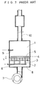
- the prior art combustor as shown in accompanying Fig. 7, has a cylindrical combustion chamber 1, a nozzle plate 4 with a plurality of gas nozzles 2 and a plurality of air nozzles 3 arranged in the combustion chamber 1, and a circular resistant plate 5 disposed opposite to the nozzle plate 4 via a predetermined narrow space S.
- a jet of rich air/fuel mixture running through a gas conduit 6 is supplied from each of the gas nozzles 2 to the combustion chamber 1 while a jet of secondary air fed to an air chamber 8 by means of a fan 7 is supplied from each of the air nozzles 3 to the combustion chamber 1.
- the rich air/fuel mixture and the secondary air are sufficiently mixed between the resistant plate 5 and the nozzle plate 4, and ignited by a spark of an ignition plug 9 in the combustion chamber 1 for pulse combustion.
- a large portion of hot combustion byproducts is exhausted through a tail pipe 10. Although the high explosion pressure in the combustion chamber 1 tends to cause a back flow of the combustion byproducts to the supply source, the resistant plate 5 in the combustion chamber 1 prevents such undesirable back flow.
- the pulse combustor of the prior art system requires a high-pressure fan or a compressor for supplying the high-pressure air and a complicated, rather bulky gas supply unit for supplying the high-pressure fuel gas. These structures unfavorably increase the noise and vibration.
- the rich air/fuel mixture and the secondary air are mixed only in the predetermined narrow space S between the resistant plate 5 and the nozzle plate 4, which causes non-uniform mixing and thereby unstable combustion.
- the object of the invention is to provide a simply constructed, improved pulse combustor which realizes stable, continuous combustion with reduced noise and vibration.
- a pulse combustor of the invention wherein a rich mixture of primary air and gaseous fuel and a secondary air are separately supplied to a cylindrical combustion chamber for pulsative ignition and continuous combustion of an appropriate air/fuel mixture.
- the pulse combustor of the invention includes the cylindrical combustion chamber having a predetermined first volume for receiving the rich mixture of primary air and gaseous fuel and the secondary air separately, a tail pipe connecting to the combustion chamber for exhausting hot combustion byproducts sent from the combustion chamber, and a nozzle plate having a plurality of gas nozzles for supplying the rich mixture of primary air and gaseous fuel to the combustion chamber and a plurality of air nozzles for supplying the secondary air to the combustion chamber.
- the combustion chamber is defined by a first surface which the tail pipe is connected to, a cylindrical side wall, and the nozzle plate having the plurality of gas nozzles and air nozzles.
- the pulse combustor of the invention further includes, as improvement, a flame baffle unit disposed opposite to the nozzle plate via a predetermined space for absorbing heat and reverse pressure generated by the hot combustion byproducts back flown from the combustion chamber, an air supply unit having a predetermined second volume which is greater than the predetermined first volume, for supplying the secondary air to the combustion chamber through the plurality of air nozzles and receiving the hot combustion byproducts back flown from the combustion chamber, an ever-on fan for continuously feeding the secondary air to the air supply unit, and a specific system for mixing the secondary air continuously fed to air supply unit by means of the fan with the hot combustion byproducts back flown from the combustion chamber and received by the air supply unit, and feeding mixture of the secondary air and the hot combustion byproducts back to the combustion chamber via the plurality of air nozzles.
- a flame baffle unit disposed opposite to the nozzle plate via a predetermined space for absorbing heat and reverse pressure generated by the hot combustion byproducts back flown from the combustion chamber
- an air supply unit having
- the rich mixture of primary air and gaseous fuel (hereinafter referred to as the rich air/fuel mixture) is supplied from the plurality of gas nozzles whereas the secondary air is fed from the plurality of air nozzles.
- the rich air/fuel mixture and the secondary air are sufficiently mixed in the predetermined space between the nozzle plate and the flame baffle unit and then ignited in the combustion chamber for pulsative combustion.
- the large combustion pressure in the combustion chamber exhausts a large portion of hot combustion byproducts from the tail pipe while a small portion of the combustion byproducts is back flown to the air supply unit.
- the flame baffle unit effectively prevents the large reverse pressure from being applied directly into the air supply unit, the small portion of the hot combustion byproducts flows around the flame baffle unit to go back to the air supply unit. In this pathway going around the flame baffle unit, the hot combustion byproducts are effectively cooled down, and this temperature drop further causes contraction in volume and lowers the pressure of the exhausted gas.
- the predetermined second volume of the air supply unit is greater than the predetermined first volume of the combustion chamber as described previously. Such a volume ratio significantly reduces the reverse pressure from the combustion chamber.
- the small portion of the combustion byproducts back flown to the air supply unit is sufficiently mixed with the secondary air and thereby does not cause any adverse effect on smooth combustion.
- the secondary air continuously fed into the air supply unit by means of the ever-on fan is mixed with the back-flown combustion byproducts and fed to the combustion chamber via the plurality of air nozzles.
- the reverse pressure from the combustion chamber is sufficiently reduced, and the fan used here for supplying the secondary air to the air supply unit does not require high pressure or large capacity, accordingly.
- the fan having moderate capacity has favorably small noise and vibration.
- the back-flow of the combustion byproducts from the combustion chamber lowers the combustion pressure in the combustion chamber.
- the combustion efficiency is largely affected by the ratio of a second volume V2 in the air supply unit (hereinafter referred to as the supply volume) to a first volume V1 in the combustion chamber (hereinafter referred to as the combustion volume).
- the concentration of carbon monoxide expressed by the ratio of CO to CO2 varies with the ratio of the supply volume V2 to the combustion volume V1.
- the supply volume V2 is less than the combustion volume V1, the combustion efficiency is undesirably lowered.
- the supply volume V2 is greater than the combustion volume V1, thus allowing sufficient reduction of the reverse pressure and realizing stable pulse combustion.
- the flame baffle unit includes a baffle plate disposed opposite to the nozzle plate via the predetermined space.
- the baffle plate extends to a predetermined length covering all of the plurality of air nozzles and gas nozzles on the nozzle plate.
- the flame baffle unit includes a first baffle plate and a second baffle plate both extending to a predetermined length covering all of the plurality of air nozzles and gas nozzles on the nozzle plate.
- the first baffle plate has a first surface and a second surface, where the first surface is disposed opposite to the nozzle plate via the predetermined space and the second surface faces the second baffle plate via a predetermined distance.
- the flame baffle unit further includes a baffle ring disposed radially along the cylindrical side wall of the combustion chamber and between the first baffle plate and the second baffle plate.
- the first baffle plate, the baffle ring, and the second baffle plate are preferably spaced at substantially equal intervals.
- the flame baffle unit includes a ring-shaped flame trap and a baffle plate disposed opposite to the nozzle plate via the predetermined space.
- the baffle plate extends to a predetermined length covering all of the air nozzles and gas nozzles on the nozzle plate whereas the ring-shaped flame trap is disposed radially between the baffle plate and the cylindrical side wall of the combustion chamber.
- the flame baffle unit includes a baffle plate disposed opposite to the nozzle plate via the predetermined space.
- the baffle plate has a plurality of through holes and spans the side wall of the combustion chamber.
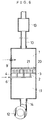
- Fig. 1 is a cross sectional view schematically illustrating a pulse combustor according to a first embodiment of the invention.
- an air chamber 11 has a greater inner volume than the air chamber 8 of the conventional system shown in Fig. 7, and an ever-on fan 12 has a moderate capacity compared with the high-pressure fan 7 of the conventional system.
- the system of the first embodiment also includes a baffle plate 15 in place of the resistant plate 5.
- the same elements as those of the conventional system have the same numerals.
- the pulse combustor of the embodiment includes a cylindrical combustion chamber 1 having a predetermined first volume, the air chamber 11 having a predetermined second volume greater than the first volume, and a nozzle plate 4 disposed between the combustion chamber 1 and the air chamber 11 to function as a partition and separate the combustion chamber 1 from the air chamber 11.
- the nozzle plate 4 is provided with a plurality of gas nozzles 2 for supplying a non-flammable rich mixture of primary air and gaseous fuel and a plurality of air nozzles 3 for supplying secondary air.
- the air chamber 11 is in communication with the combustion chamber 1 through the plurality of air nozzles 3.
- the plurality of gas nozzles 2 are connected to a gas supply conduit 6.
- the pulse combustor of the embodiment further includes the fan 12, for example, a multiblade fan, for feeding the secondary air, and an air supply conduit 14 coupled with and connected to the fan 12 to supply the secondary air to the air chamber 11. Since the air chamber 11 has a sufficiently large inner volume, the required capacity of the fan 12 is significantly reduced.
- the fan 12 for example, a multiblade fan, for feeding the secondary air
- an air supply conduit 14 coupled with and connected to the fan 12 to supply the secondary air to the air chamber 11. Since the air chamber 11 has a sufficiently large inner volume, the required capacity of the fan 12 is significantly reduced.
- the combustion chamber 1 is further connected to a tail pipe 10 for exhausting hot combustion byproducts and a decoupler or expansion chamber 13 disposed in the middle of the tail pipe 10.
- the pulse combustor may include a plurality of tail pipes, which may be disposed on a side wall of the combustion chamber 1.
- the baffle plate 15 is arranged in the combustion chamber 1 to be located opposite to the nozzle plate 4 via a predetermined narrow space S.
- the baffle plate 15 effectively absorbs the heat of the hot combustion byproducts back flowing from the combustion chamber 1 to the air chamber 11.
- a jet of a rich mixture of primary air and gaseous fuel (hereinafter referred to as the rich air/fuel mixture) running through the gas supply conduit 6 is supplied to the combustion chamber 1 via each of the gas nozzles 2 on the nozzle plate 4 as clearly seen in Fig. 1.
- a jet of secondary air fed to the air chamber 11 by means of the fan 12 is, on the other hand, supplied to the combustion chamber 1 via each of the air nozzles 3.
- the rich air/fuel mixture and the secondary air are sufficiently mixed in the predetermined space S between the baffle plate 15 and the nozzle plate 4 combusted in the combustion chamber 1.
- the nozzle plate 4 has three gas nozzles 2 (diameter: 3 millimeter) and ten air nozzles 3 (diameter: 4 millimeter).
- the thickness of the baffle plate 15 is 4 millimeter, and the predetermined narrow space S between the baffle plate 15 and the nozzle plate 4 is equal to 3 millimeter.
- the sufficiently mixed rich air/fuel mixture and secondary air (hereinafter referred to as the air/fuel mixture) is ignited with a spark of an ignition plug 9 in the combustion chamber 1 for pulse combustion.
- the high explosion and combustion pressure in the combustion chamber 1 exhausts a large portion of hot combustion byproducts through the tail pipe 10 whereas a small portion of the hot combustion byproducts flows back to the air chamber 11.
- the baffle plate 15 prevents the large reverse pressure from being applied into the air chamber 11 directly, the small portion of the combustion byproducts flows around the baffle plate 15 to go back to the air chamber 11. In this pathway around the baffle plate 15, the hot combustion byproducts are effectively cooled down, and this temperature drop further causes contraction in volume and lowers the pressure of the exhausted gas. Since the second volume of the air chamber 11 is greater than the first volume of the combustion chamber 1 as described previously, the reverse pressure from the combustion chamber 1 is significantly reduced, and the combustion byproducts back flown to the air chamber 1 is sufficiently mixed with the secondary air.
- the secondary air continuously fed into the air chamber 11 by means of the ever-on fan 12 is mixed with the back-flown combustion byproducts and fed to the combustion chamber 1 via the plurality of air nozzles 3.
- the reverse pressure from the combustion chamber 1 is sufficiently low, and the fan 12 used here for supplying the secondary air to the air chamber 11 does not require high pressure or large capacity, accordingly.
- the fan 12 having moderate capacity has favorably small noise and vibration.
- the back-flow of the combustion byproducts from the combustion chamber 1 lowers the combustion pressure in the combustion chamber 1, thus reducing the combustion noise.
- the turn-down ratio can be raised preferably by controlling the air supply volume fed by the fan 12 and the volume of the rich air/fuel mixture.
- the combustion efficiency is largely affected by the ratio of a total volume V2 of an air supply system (the volume of the air chamber 11 plus that of the air supply conduit 14: hereinafter referred to as the supply volume V2) to a volume V1 of the combustion chamber 1 (hereinafter referred to as the combustion volume V1).
- Fig. 2 shows variation in the concentration of carbon monoxide (expressed as the ratio of CO/ CO2) plotted against the ratio of the supply volume V2 to the combustion volume V1. In the range where the supply volume V2 is less than the combustion volume V1, the concentration of CO is significantly high; that is, the combustion efficiency is undesirably low.
- the CO concentration first abruptly decreases and then gradually increases with increase in the ratio of the supply volume V2 to the combustion volume V1.
- the CO concentration is sufficiently low; that is, the combustion efficiency is preferably high.
- the smaller supply volume V2 than the combustion volume V1 causes insufficient mixing of the back-flown combustion byproducts with the secondary air, thus lowering the combustion efficiency. Furthermore, the small supply volume V2 does not sufficiently reduce the reverse pressure and requires a relatively large capacity of the fan 12.
- the supply volume V2 is greater than the combustion volume V1, the smaller pressure loss and leaner air/fuel ratio increase the CO concentration only in the allowable range.
- the supply volume V2 is determined to be sufficiently larger than the combustion volume V1 so as to lower the CO concentration to the minimum, thus significantly improving the combustion efficiency.
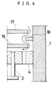
- a pulse combustor of the second embodiment includes a plurality of baffle plates for improvement in heat absorption effects. More concretely, the pulse combustor as shown in Fig. 3 includes a first baffle plate 16 and a second baffle plate 17 both extending to a predetermined length covering all of the plurality of air nozzles 3 and gas nozzles 2 on the nozzle plate 4.
- the first baffle plate 16 has a first surface and a second surface, where the first surface is disposed opposite to the nozzle plate 4 via a predetermined first distance and the second surface faces the second baffle plate 17 via a predetermined second distance.
- the first baffle plate 16 and the second baffle plate 17 have identical dimensions in this embodiment.
- the pulse combustor is further provided with a baffle ring 18 disposed radially along a cylindrical side wall of the combustion chamber 1 and between the first baffle plate 16 and the second baffle plate 17.
- the first baffle plate 16, the baffle ring 18, and the second baffle plate 17 are spaced at substantially equal intervals as clearly seen in Fig. 4.
- the heat of hot combustion byproducts back flown to the air chamber 11 is efficiently absorbed through a zigzag pathway through the second baffle plate 17, the baffle ring 18, and the first baffle plate 16.
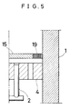
- Fig. 5 shows an essential part of another pulse combustor as a third embodiment of the invention.
- the pulse combustor of the third embodiment has a similar structure to that of the first embodiment, except a flame trap ring 19 is arranged between a cylindrical side wall of the combustion chamber 1 and the baffle plate 15.
- the flame trap ring 19 has a ceramic honeycomb structure of 600 cells, where each cell denotes the number of pores in one square inch.
- the flame trap 19 and the baffle plate 15 of this structure also efficiently absorb the heat of hot combustion byproducts back flown to the air chamber 11 (see Fig. 1).
- Fig. 6 shows still another pulse combustor as a fourth embodiment according to the invention.
- a punching metal 20 having a plurality of apertures 21 is disposed opposite to the nozzle plate 4 to span the whole length of the cylindrical combustion chamber 1.
- the plurality of apertures 21 formed in the punched metal 20 are arranged eccentrically with any of the plural gas nozzles 2 and the air nozzles 3.
- This eccentric structure effectively prevents the reverse pressure from the combustion chamber 1 from being applied into an air supply system directly.
- the structure of the fourth embodiment also ensures efficient mixing of the back-flown combustion byproducts with the secondary air and efficiently absorbs the heat of the hot combustion byproducts.
- the supply volume is set greater than the combustion volume to allow the combustion byproducts to be partly back flown to the air supply system.
- the back-flown combustion byproducts are sufficiently mixed with the secondary air continuously fed by means of the ever-on fan and fed back to the combustion chamber.
Landscapes
- Engineering & Computer Science (AREA)
- Chemical & Material Sciences (AREA)
- Combustion & Propulsion (AREA)
- Mechanical Engineering (AREA)
- General Engineering & Computer Science (AREA)
- Fluidized-Bed Combustion And Resonant Combustion (AREA)
Priority Applications (3)
| Application Number | Priority Date | Filing Date | Title |
|---|---|---|---|
| DE69310917T DE69310917T2 (de) | 1993-12-10 | 1993-12-10 | Gerät mit pulsierender Verbrennung |
| EP93309944A EP0657690B1 (de) | 1993-12-10 | 1993-12-10 | Gerät mit pulsierender Verbrennung |
| ES93309944T ES2104077T3 (es) | 1993-12-10 | 1993-12-10 | Combustor de impulsos. |
Applications Claiming Priority (1)
| Application Number | Priority Date | Filing Date | Title |
|---|---|---|---|
| EP93309944A EP0657690B1 (de) | 1993-12-10 | 1993-12-10 | Gerät mit pulsierender Verbrennung |
Publications (2)
| Publication Number | Publication Date |
|---|---|
| EP0657690A1 true EP0657690A1 (de) | 1995-06-14 |
| EP0657690B1 EP0657690B1 (de) | 1997-05-21 |
Family
ID=8214632
Family Applications (1)
| Application Number | Title | Priority Date | Filing Date |
|---|---|---|---|
| EP93309944A Expired - Lifetime EP0657690B1 (de) | 1993-12-10 | 1993-12-10 | Gerät mit pulsierender Verbrennung |
Country Status (3)
| Country | Link |
|---|---|
| EP (1) | EP0657690B1 (de) |
| DE (1) | DE69310917T2 (de) |
| ES (1) | ES2104077T3 (de) |
Citations (3)
| Publication number | Priority date | Publication date | Assignee | Title |
|---|---|---|---|---|
| US4891003A (en) * | 1987-07-15 | 1990-01-02 | Paloma Kogyo Kabushiki Kaisha | Pulse combustion device |
| EP0527656A2 (de) * | 1991-08-13 | 1993-02-17 | Paloma Kogyo Kabushiki Kaisha | Gerät mit pulsierender Verbrennung |
| EP0556038A2 (de) * | 1992-02-14 | 1993-08-18 | Paloma Kogyo Kabushiki Kaisha | Fritiergerät für Handelszwecke |
-
1993
- 1993-12-10 ES ES93309944T patent/ES2104077T3/es not_active Expired - Lifetime
- 1993-12-10 DE DE69310917T patent/DE69310917T2/de not_active Expired - Fee Related
- 1993-12-10 EP EP93309944A patent/EP0657690B1/de not_active Expired - Lifetime
Patent Citations (3)
| Publication number | Priority date | Publication date | Assignee | Title |
|---|---|---|---|---|
| US4891003A (en) * | 1987-07-15 | 1990-01-02 | Paloma Kogyo Kabushiki Kaisha | Pulse combustion device |
| EP0527656A2 (de) * | 1991-08-13 | 1993-02-17 | Paloma Kogyo Kabushiki Kaisha | Gerät mit pulsierender Verbrennung |
| EP0556038A2 (de) * | 1992-02-14 | 1993-08-18 | Paloma Kogyo Kabushiki Kaisha | Fritiergerät für Handelszwecke |
Also Published As
| Publication number | Publication date |
|---|---|
| EP0657690B1 (de) | 1997-05-21 |
| ES2104077T3 (es) | 1997-10-01 |
| DE69310917D1 (de) | 1997-06-26 |
| DE69310917T2 (de) | 1998-01-08 |
Similar Documents
| Publication | Publication Date | Title |
|---|---|---|
| US6916175B2 (en) | Combustion gas burner enabling multi-stage control | |
| US6267585B1 (en) | Method and combustor for combusting hydrogen | |
| US7997058B2 (en) | Apparatus for mixing substances | |
| EP0356092B1 (de) | Gasturbinenbrennkammer | |
| US4194358A (en) | Double annular combustor configuration | |
| US6662564B2 (en) | Catalytic combustor cooling tube vibration dampening device | |
| US5611196A (en) | Fuel/air mixing device for gas turbine combustor | |
| US20070089419A1 (en) | Combustor for gas turbine engine | |
| US6966186B2 (en) | Non-catalytic combustor for reducing NOx emissions | |
| US5588822A (en) | Flame trap for use in a pulse combustor | |
| CN1502007A (zh) | 用于能源系统的环形燃烧室 | |
| US20040112057A1 (en) | Catalytic oxidation module for a gas turbine engine | |
| US6918759B2 (en) | Premixed combustion gas burner having separated fire hole units | |
| US4997362A (en) | Ceramic burner | |
| EP0527657B1 (de) | Gerät mit pulsierender Verbrennung | |
| EP0657690A1 (de) | Gerät mit pulsierender Verbrennung | |
| EP0527656B1 (de) | Gerät mit pulsierender Verbrennung | |
| JP2003148733A (ja) | ガスタービン燃焼器、及びこれを備えたガスタービン | |
| JPH1163417A (ja) | 2段燃焼器 | |
| RU2241177C2 (ru) | Камера сгорания | |
| JP3109361B2 (ja) | 燃焼装置 | |
| JP3151761B2 (ja) | 燃焼装置 | |
| JP3375663B2 (ja) | 触媒燃焼器 | |
| KR0150381B1 (ko) | 가스버너용 염공판구조 | |
| JPH07103424A (ja) | 濃淡燃焼装置 |
Legal Events
| Date | Code | Title | Description |
|---|---|---|---|
| PUAI | Public reference made under article 153(3) epc to a published international application that has entered the european phase |
Free format text: ORIGINAL CODE: 0009012 |
|
| AK | Designated contracting states |
Kind code of ref document: A1 Designated state(s): DE ES FR GB IT |
|
| 17P | Request for examination filed |
Effective date: 19950926 |
|
| 17Q | First examination report despatched |
Effective date: 19960425 |
|
| GRAG | Despatch of communication of intention to grant |
Free format text: ORIGINAL CODE: EPIDOS AGRA |
|
| GRAH | Despatch of communication of intention to grant a patent |
Free format text: ORIGINAL CODE: EPIDOS IGRA |
|
| GRAH | Despatch of communication of intention to grant a patent |
Free format text: ORIGINAL CODE: EPIDOS IGRA |
|
| GRAA | (expected) grant |
Free format text: ORIGINAL CODE: 0009210 |
|
| ITF | It: translation for a ep patent filed | ||
| AK | Designated contracting states |
Kind code of ref document: B1 Designated state(s): DE ES FR GB IT |
|
| REF | Corresponds to: |
Ref document number: 69310917 Country of ref document: DE Date of ref document: 19970626 |
|
| ET | Fr: translation filed | ||
| REG | Reference to a national code |
Ref country code: ES Ref legal event code: FG2A Ref document number: 2104077 Country of ref document: ES Kind code of ref document: T3 |
|
| PLBE | No opposition filed within time limit |
Free format text: ORIGINAL CODE: 0009261 |
|
| STAA | Information on the status of an ep patent application or granted ep patent |
Free format text: STATUS: NO OPPOSITION FILED WITHIN TIME LIMIT |
|
| 26N | No opposition filed | ||
| REG | Reference to a national code |
Ref country code: GB Ref legal event code: IF02 |
|
| PGFP | Annual fee paid to national office [announced via postgrant information from national office to epo] |
Ref country code: DE Payment date: 20041202 Year of fee payment: 12 |
|
| PG25 | Lapsed in a contracting state [announced via postgrant information from national office to epo] |
Ref country code: DE Free format text: LAPSE BECAUSE OF NON-PAYMENT OF DUE FEES Effective date: 20060701 |
|
| PGFP | Annual fee paid to national office [announced via postgrant information from national office to epo] |
Ref country code: GB Payment date: 20101208 Year of fee payment: 18 Ref country code: IT Payment date: 20101218 Year of fee payment: 18 |
|
| PGFP | Annual fee paid to national office [announced via postgrant information from national office to epo] |
Ref country code: ES Payment date: 20111228 Year of fee payment: 19 Ref country code: FR Payment date: 20111219 Year of fee payment: 19 |
|
| GBPC | Gb: european patent ceased through non-payment of renewal fee |
Effective date: 20121210 |
|
| REG | Reference to a national code |
Ref country code: FR Ref legal event code: ST Effective date: 20130830 |
|
| PG25 | Lapsed in a contracting state [announced via postgrant information from national office to epo] |
Ref country code: FR Free format text: LAPSE BECAUSE OF NON-PAYMENT OF DUE FEES Effective date: 20130102 Ref country code: GB Free format text: LAPSE BECAUSE OF NON-PAYMENT OF DUE FEES Effective date: 20121210 |
|
| PG25 | Lapsed in a contracting state [announced via postgrant information from national office to epo] |
Ref country code: IT Free format text: LAPSE BECAUSE OF NON-PAYMENT OF DUE FEES Effective date: 20121210 |
|
| REG | Reference to a national code |
Ref country code: ES Ref legal event code: FD2A Effective date: 20140306 |
|
| PG25 | Lapsed in a contracting state [announced via postgrant information from national office to epo] |
Ref country code: ES Free format text: LAPSE BECAUSE OF NON-PAYMENT OF DUE FEES Effective date: 20121211 |