EP0657844A2 - Appareil et méthode d'impression - Google Patents
Appareil et méthode d'impression Download PDFInfo
- Publication number
- EP0657844A2 EP0657844A2 EP94117859A EP94117859A EP0657844A2 EP 0657844 A2 EP0657844 A2 EP 0657844A2 EP 94117859 A EP94117859 A EP 94117859A EP 94117859 A EP94117859 A EP 94117859A EP 0657844 A2 EP0657844 A2 EP 0657844A2
- Authority
- EP
- European Patent Office
- Prior art keywords
- data
- display list
- memory
- resolving power
- dpi
- Prior art date
- Legal status (The legal status is an assumption and is not a legal conclusion. Google has not performed a legal analysis and makes no representation as to the accuracy of the status listed.)
- Granted
Links
Images


Classifications
-
- G—PHYSICS
- G06—COMPUTING OR CALCULATING; COUNTING
- G06K—GRAPHICAL DATA READING; PRESENTATION OF DATA; RECORD CARRIERS; HANDLING RECORD CARRIERS
- G06K15/00—Arrangements for producing a permanent visual presentation of the output data, e.g. computer output printers
- G06K15/02—Arrangements for producing a permanent visual presentation of the output data, e.g. computer output printers using printers
-
- G—PHYSICS
- G06—COMPUTING OR CALCULATING; COUNTING
- G06K—GRAPHICAL DATA READING; PRESENTATION OF DATA; RECORD CARRIERS; HANDLING RECORD CARRIERS
- G06K2215/00—Arrangements for producing a permanent visual presentation of the output data
- G06K2215/0002—Handling the output data
- G06K2215/0005—Accepting output data; Preparing data for the controlling system
- G06K2215/0014—Transforming the printer input data into internal codes
-
- G—PHYSICS
- G06—COMPUTING OR CALCULATING; COUNTING
- G06K—GRAPHICAL DATA READING; PRESENTATION OF DATA; RECORD CARRIERS; HANDLING RECORD CARRIERS
- G06K2215/00—Arrangements for producing a permanent visual presentation of the output data
- G06K2215/0002—Handling the output data
- G06K2215/0062—Handling the output data combining generic and host data, e.g. filling a raster
- G06K2215/0065—Page or partial page composition
Definitions
- the present invention relates to a printing apparatus for receiving input data from an information processing apparatus such as a host computer and generating and printing output data, and a printing method therefor.
- a full-raster image of the image to be printed has to be prepared in a bit map memory, prior to the printing operation. This is based on a fact that the page printing operation of the printing apparatus is conducted with the scanning process of a constant speed. Once the page printing operation is initiated, the printing process is conducted with a constant speed until said operation is completed. Consequently, in order to avoid a situation called data underflow, in which the data to be printed are deficient in the print engine, the entire image to be printed is converted into a raster image in the bit map memory prior to the printing operation.
- a CPU in the printing apparatus monitors the bit map memory and confirms that the raster image is supplied to the printer engine with the speed of the printing operation.
- bit map memory For printing a simple black-and-white image of a low resolving power, for example of 300 dot/inch (dpi), on a standard-sized sheet for example of 8 1 2 " x 11" with such printing system, there is required a bit map memory of about 1 megabytes (Mb). Since such memory of 1 Mb is inexpensive, it is not critical even if a major part of the memory is not used for a long time. The situation is same also when the bit map memory has a capacity of 2 Mb, constituting a double buffer memory system.
- Such double buffer system is preferable in that the image data of the current page can be printed from a buffer while the CPU prepares the raster image in the other buffer from the image data of a next page.
- double buffer system allows to continuously transfer the raster image data to the printer engine, thereby improving the throughput in the page without significant increase in the cost.
- the object of the present invention is to provide a printing apparatus, and a method therefor, capable of bit map development with or without reduction in the resolving power according to the available capacity of the bit map memory.
- a printing apparatus comprising: discrimination means for discriminating whether a memory capable of storing second data can be secured; and selection means for selecting either a first mode for generating second data from first data with a first resolving power or a second mode for generating second data from first data with a second resolving power lower than said first resolving power, according to the result of discrimination by said discrimination means.
- a printing method comprising steps of: discriminating whether a memory capable of storing second data can be secured; and selecting either a first mode for generating second data from first data with a first resolving power, or a second mode for generating second data from first data with a second resolving power lower than said first resolving power, according to the result of said discrimination.
- the first mode maintaining the resolving power
- the second mode reducing the resolving power
- Fig. 1 is a cross-sectional view of an image output device, for example a laser beam printer, in which the present invention is applicable.
- a main body 100 of the laser beam printer which stores character information (character codes), format information and macroinstructions received from an externally connected host computer 201 and generates character patterns and form patterns according to such information, thereby recording an image on a recording sheet constituting the recording medium.
- an operation panel 112 equipped with operation switches, LED display devices etc.
- a printer control unit 101 for controlling the entire main body 100 and analyzing the character information etc. supplied from the host computer.
- Said printer control unit 101 principally converts the character information into a video signal of corresponding character patterns, for supply to a laser driver 102.
- the laser driver 102 provided for driving a semiconductor laser 103, effects on-off control of the laser beam 104 emitted from the semiconductor laser 103, according to the input video signal.
- the laser beam 104 is deflected in the lateral direction by a rotary polygon mirror 105 and scans the surface of an electrostatic drum 106.
- electrostatic drum 106 On said electrostatic drum 106 there is thus formed an electrostatic latent image of the character pattern, and said latent image is developed into a visible image by a developing unit 107 provided around the drum 106 and is transferred onto a recording sheet.
- the recording sheets of a cut sheet form are stored in a sheet cassette 108 mounted in the main body 100, and supplied to the electrostatic drum by means of a feed roller 109 and transport rollers 110, 111.
- Fig. 8 is a block diagram showing the configuration of an image processing apparatus for achieving secure printing process by reducing the resolving power.
- a host computer 201 is connected, through an unrepresented interface connector, with the control unit 101, which is so constructed as to effect the printing operation by receiving input data, consisting of commands and character codes, from the host computer 201.
- a CPU 203 for effecting calculations and controls for an engine unit (not shown);
- a reception buffer 202 for temporarily storing the input data, consisting of commands and character codes, from the host computer 201;
- a program ROM 204 storing programs for executing the control sequences to be explained later in relation to Fig.
- a font ROM 206 storing font scaler programs for generating character font patterns and outline fonts
- a RAM 207 serving as a work area
- a memory 212 for intermediate data (display list) and a memory 213 for output data (bit map data) in the program execution by the CPU 203
- an image output unit 205 for supplying the printer engine with the output data.
- the control unit 101 is powered by an unrepresented power source unit.
- the program ROM 204 stores, as processing programs, a band drawing unit 208, a display list memory administration unit 209, a drawing time administration unit 210, and a display list reduction unit 211.
- Fig. 9 is a flow chart showing an example of the drawing process for the RAM 207 shown in Fig. 8, wherein parentheses (1) - (10) indicate process steps.
- step 1 When the main body is powered, there are conducted initialization of a display list storage unit 212 and a band raster storage unit 213 and setting of the resolving power of the display list to be prepared in the step (4) (step 1).
- the structure of said display list storage unit 212 and band raster storage unit 213 will be explained later.
- the input data are received from the host computer 201 (step 2), and are stored in the reception buffer 202, and data of a unit code are read therefrom. Said received data are analyzed as a command (step 3), and display list (intermediate data) of 600 dpi is generated from said command (step 4).
- the display list memory administration unit 209 discriminates whether a memory can be acquired from the display list storage unit 212 (step 5), and, if acquirable, said prepared display list is stored in the acquired memory (step 6).
- the drawing time administration unit 210 predicts the time required for drawing the prepared display list in the band raster storage unit 213, and adds said time to a band administration table.
- step 7 there is discriminated whether the drawing time from the display list to the band raster is shorter than the output time from the band raster storage unit 213 to the image output unit (step 7), and, if shorter, the sequence returns to the step (2) to await the next data input.
- step (7) if the step (7) identifies that the added drawing time is longer than the output time from the band raster storage unit 213 to the image output unit 205, the sequence proceeds to a step (8) to effect, in the display list reduction unit 211, the conversion of the resolving power of the object of 600 dpi in the already prepared display list to an object of 300 dpi (step 8), and the resolving power of the display list generated in the step (4) is set at 300 dpi (step 9). Subsequently the sequence returns to the step (2) to await the next data input. On the other hand, if the step (5) identifies that the memory is not acquirable, the sequence proceeds to the step (8).
- the character dot pattern of 600 dpi contained in the display list (intermediate data) of 600 dpi is subjected to a skipping process to generate a character dot pattern of 300 dpi.
- step (3) identifies a sheet discharge command
- the display list is drawn, for each band, in the band raster storage area (step 10).
- the drawing is executed respectively with the band raster selected at 600 or 300 dpi.
- the band raster after said drawing is supplied, by the image output unit 205, to the printer engine.
- the band raster storage unit 213 has a capacity-of two bands, so that the drawing operation can be conducted in one band while the other is supplied to the printer engine.
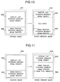
- Figs. 10 and 11 are schematic views showing the structures respectively of the display list storage unit 212 and the band raster storage unit 213 shown in Fig. 8.
- 401 indicates a normal memory state, in which a display list of 600 dpi is generated in a display list storage area 402. Also in the page discharging operation, the display list stored in the display list storage area 402 is drawn, for each band, in a band raster storage area 403 with a resolving power of 600 dpi.
- the display list memory administration unit 209 identifies that the capacity of the display list is larger than a predetermined capacity, or when the drawing time administration unit 210 identifies that the drawing time required for drawing the display list in the band rasters is longer than a predetermined time.
- the 600-dpi object in the display list storage area 402 in the normal state is converted, by the conversion of the resolving power to 300 dpi by the display list reducing unit 211, to a converted display list storage area 405.
- the band raster storage area 403 in the normal state is converted, in the resolving power from 600 dpi to 300 dpi, to a band raster storage area 406.
- an empty area is formed in the display list storage area 405. Also as the drawing time of the display list of 300 dpi is shorter than that of the display list of 600 dpi, it is possible, in the page discharging operation, to release the already drawn band rasters to the image output unit 205 while the display list, stored in the display list storage area 405, is drawn for each band in the band raster storage area 406 with a resolving power of 300 dpi.
- the display list generated by the display list generating operation is of 300 dpi.
- 501 indicates a normal memory state, in which, in a display list storage area 502, a display list of 600 dpi is generated. Also in the band drawing (page output) operation, the display list stored in the display list storage area 502 is drawn with a resolving power of 600 dpi in a band raster storage area 503.
- the 504 indicates a memory state when the display list memory administration unit 209 identifies that the capacity of the display list is larger than a predetermined capacity, or when the drawing time administration unit 211 identifies that the time required for drawing the display list in the band rasters is longer than a predetermined time.
- a 600-dpi object in the display list storage area 502 in the normal state is converted by the display list reducing unit 211 into a 300-dpi object, and is drawn in a band raster storage area 506 with a resolving power of 300 dpi.
- the display list of 600 dpi in the display list storage area 502 is converted to 300 dpi and is all drawn in the band raster storage area 506.
- the display list generation process generates a display list of 300 dpi, which is stored in the display list storage area 505.
- the prepared display list of 300 dpi may be directly drawn in the band raster storage area 506.
- Fig. 12 shows an example of the display list in the image processing apparatus of the kind explained above.
- the display list (intermediate data) means a group of data (printer language consisting of character codes and control codes) received for example from the host computer and represented in a format easily convertible into bit map data in the printing apparatus.
- a band table 1201 for dividing a page into plural bands and administering the drawing object in each band; a drawing unit (application) 1202 for administering the print position of the actual drawing object; a drawing object (bit map, font) 1204; and an object table 1203 for administering the drawing objects.
- the display list means a list of the above-mentioned data 1201 - 1204.
- the band table 1201 has application links to the bands.
- the application 1202 has a pointer to the next application, print positions X, Y in the band, an object number of the drawing object, and a scan line offset from the start of the drawing object to the print start position within the band.
- the object table 1203 has pointers to the drawing objects.
- the drawing object 1204 has the width and height of the object and a drawing bit map.
- Fig. 13 is a schematic view of an example of the rasterized development based on the display list shown in Fig. 12.
- the application is developed in each band and drawn in rasterized format, thereby obtaining the output image in the raster memory.
- Fig. 2 is a block diagram of the configuration of an image process apparatus capable of secure printing operation without reduction in the resolving power, wherein same components as those in Fig. 8 are represented by same numbers.
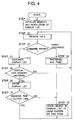
- a CPU 203a controls the drawing development according to the sequence shown in Fig. 4, which is a flow chart of the image processing sequence to be executed in the image processing apparatus shown in Fig. 2, wherein (1) to (9) indicate process steps.
- step 1 When the main body is powered, there are conducted initialization of the display list storage unit 212 and the band raster storage unit 213 and setting of the resolving power of the display list to be prepared in the step (4) (step 1).
- the structure of said display list storage unit 212 and band raster storage unit 213 will be explained later.
- the input data are received from the host computer 201 (step 2), and are stored in the reception buffer 202, and data of a unit code are read therefrom. Said received data are analyzed as a command (step 3), and display list of 600 dpi is generated from said command (step 4). Then the display list memory administration unit 209 discriminates whether a memory can be acquired from the display list storage unit 212 (step 5), and, if acquirable, said prepared display list is stored in the acquired memory (step 6). Subsequently the drawing time administration unit 210 predicts the time required for drawing the prepared display list in the band raster storage unit 213, and adds said time to a band administration table.
- step 7 there is discriminated whether the drawing time from the display list to the band raster is shorter than the output time from the band raster storage unit 213 to the image output unit (step 7), and, if shorter, the sequence returns to the step (2) to await the next data input.
- step (7) if the step (7) identifies that the added drawing time is longer than the output time from the band raster storage unit 213 to the image output unit 205, the sequence proceeds to a step (8) to draw a page of the 600-dpi object in the already prepared display list, by the band drawing unit 208, in the band raster storage unit 606 without reduction of the resolving power (step 8). Subsequently the sequence returns to the step (2) to await the next data input. On the other hand, if the step (5) identifies that the memory is not acquirable, the sequence proceeds to the step (8). The details of said step (8) will be explained later with reference to Fig. 14.
- step (3) identifies a sheet discharge command
- the display list is drawn, for each band, in the band raster storage area (step 9).
- Fig. 3 is a schematic view showing a first memory map of the RAM 207 shown in Fig. 2.
- the 601 indicates a normal memory state, in which a display list of 600 dpi is generated in a display list storage area 602. Also in the band drawing (page output) operation, the display list stored in the display list storage area 602 is drawn in a band raster storage area 603 with a resolving power of 600 dpi.
- 604 indicates a memory state when the display list memory administration unit 209 identifies that the capacity of the display list is larger than a predetermined capacity, or when the drawing time administration unit 210 identifies that the time required for drawing the display list in the band raster memory is longer than a predetermined time.
- the 600-dpi object in the display list storage area 602 in the normal state is drawn with a resolving power of 600 dpi in the band raster storage area 606.
- the display list of 600 dpi in the display list storage area 602 is drawn, for a page amount, in the band raster storage area 606 without conversion of the resolving power.
- a hatched empty area made available by conversion of the display list in said hatched portion of the display list storage area 602 into bit map data and storage thereof in the band raster storage area 603, is assigned for the band raster storage area 606, whereby a memory area of a page is secured. Such operation is repeated to always secure the band raster storage area of a full page.
- the display list generating operation prepares a display list of 600 dpi, which is stored in the display list storage area 605.
- the prepared display list of 600 dpi may be directly drawn in the band raster storage area 606.
- all the display list is drawn in the band raster storage area if the capacity of the display list is larger than a predetermined capacity of if the time of drawing of the display list into the band raster storage area is longer than a predetermined time.
- an automatic switching function for the bit map memory according to the memory capacity in such a manner that, when the sub of the capacity of the display list storage area is small, a conversion to a lower resolving power from 600 dpi to 300 dpi is conducted by the display list reducing unit 211 and the display list of the lower resolving power in the display list storage area is drawn into the band raster storage area with a resolving power of 300 dpi if the display list memory administration unit 209 identifies that the capacity of the display list is larger than a predetermined capacity or if the drawing time administration unit 210 identifies that the time required for drawing the display list into the band rasters is longer than a predetermined time, and, when the sum of the capacity of the display list storage area 212 and the band raster storage area is larger, all the display list is drawn into the band rasters without reduction of the resolving power if the capacity of the display list is larger than a predetermined capacity or if the time required for drawing
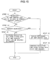
- Fig. 15 is a flow chart showing the sequence of such automatic switching function.
- a corresponding program is stored in the program ROM 204 and is executed by the CPU 203.
- a step (1) the CPU 203 discriminates whether the required bit map memory (band raster storage area) can be currently secured in the RAM 207. For example there is discriminated whether a bit map memory, capable of storing bit map data of a designated sheet size, can be secured. If said step (1) identifies that such bit map memory is securable, a step (2) secures the necessary bit map memory, and a step (3) draws the intermediate data in thus secured bit map memory, with a maintained resolving power as already explained with reference to Figs. 4 and 14, thereby generating bit map data.
- a step (4) discriminates whether an unrepresented expansion memory is connected, and, if connected, the process of the step (2) is executed.
- a step (5) generates the bit map data by drawing the intermediate data in the currently securable bit map memory with a reduction of the resolving power from 600 dpi to 300 dpi as already explained in relation to Fig. 9.
- bit map data are released through the image output unit 205 and printed.
- Fig. 5 is a schematic view showing the configuration of a second memory map in the RAM 207 shown in Fig. 2.
- the 701 indicates a normal memory state in which a display list of 600 dpi is generated in a display list storage area 702.
- the display list stored in the display list storage area 702 is drawn with a resolving power of 600 dpi in a band raster storage area 703.
- the 704 indicates a memory state when the display list memory administration unit 209 identifies that the capacity of the display list is larger than a predetermined capacity or when the drawing time administration unit 210 identifies that the time required for drawing the display list in the band raster storage area is longer than a predetermined time.
- the 600-dpi object in the display list storage area 702 in the normal state is successively drawn in a band raster storage area 706 with an unreduced resolving power of 600 dpi.
- the display list of 600 dpi in the display list storage area 702 is all drawn, for a page amount, into the band rasters 706 without the conversion to a lower resolving power, and said band rasters are stored after compression.
- the CPU 203a draws the display list in the band rasters and stores the drawn band rasters after compression, in case the capacity of the display list is larger than a predetermined capacity or in case the time required for drawing the display list in the band rasters is longer than a predetermined time. It is therefore rendered possible to securely prevent the drawing control means from conversion of the rasterized output image to a lower resolving power in the above-mentioned cases.
- the display list generation process prepares the display list with a resolving power of 600 dpi, and the prepared display list is stored in the display list storage area 705. After the latter memory state is reached, the prepared display list may be directly drawn in the band raster storage area 706.
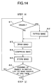
- Fig. 14 is a flow chart showing the details of the step (8) in Fig. 4.
- a step 8-1 the CPU 203 discriminates whether a band area, containing an object to be drawn, has already been drawn. For example, in case of drawing the upper part of a character pattern B shown in Fig. 13 in a O band area, there is discriminated whether said O band area has already been drawn. If the step 8-1 identifies that the band area containing the object to be drawn has already been drawn, a step 8-2 expands the compressed data of said band area, and a step 8-3 draws (effecting bit map development) the object to be drawn, on thus expanded bit map data of said band area. For example, for drawing the upper part of the character pattern B shown in Fig. 13 in the O band area, the compressed data of the O band area, containing the compressed data of the upper part of the character pattern A, are expanded and the upper part of the character pattern B is drawn on thus expanded bit map data of the O band area.
- a step 8-3 draws said object
- a step 8-4 effects compression
- a step 8-5 effects storage in the band raster storage area 213.
- a step 8-6 discriminates whether all the objects in the display list have been drawn, by a page amount, in the band rasters, and, if a page has been drawn, the sequence returns to the step (2), but if a page has not been drawn, the sequence returns to the step 8-1 for repeating the above-explained sequence.
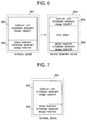
- Fig. 6 is a schematic view showing the structure of a third memory map in the RAM 207 shown in Fig. 8.
- the 801 indicates a normal memory state, in which a display list of 600 dpi is generated in a display list storage area 802.
- the display list stored in the display list storage area 802 is drawn with a resolving power of 600 dpi in a band raster storage area 803.
- the 600-dpi object in the display list storage area 802 in the normal state is re-generated as a 300-dpi object by the display list reducing unit 211, and drawing in the band raster storage area 806 is conducted with a resolving power of 300 dpi. In this manner the display list of 600 dpi in the display list storage area 802 is regenerated into 300 dpi, and is all drawn in the band raster storage area 806.
- the above-mentioned regeneration process means generation, by means of a font scaler (program) in the font ROM 206, of a character pattern of 300 dpi size, same as the character pattern of 600 dpi contained in the 600-dpi object.
- the character pattern of 300 dpi is generated anew, without the skipping process of the original character pattern, so that there can be generated and printed the output data of 300 dpi of a high quality.
- the font object in the display list storage area 802 is given, in advance by the CPU 203, certain information such as font ID and character code capable of re-scaling, and the CPU 203 and generate and print output data (bit map data) of 300 dpi of high quality, based on said information.
- the CPU 203a regenerates the display list of a lower resolving power from the information of the original display list and stores said regenerated display list in the display list storage area 212, in case the capacity of said display list is larger than a predetermined capacity or in case the time required for drawing the display list in the band rasters is longer than a predetermined time, so that the deterioration in the image quality can be minimized.
- the display generation process prepares a display list of 300 dpi, and the prepared display list is stored in the display list storage area 805.
- the prepared display list of 300 dpi may be directly drawn in the band raster storage area 806.
- Fig. 7 is a schematic view showing the configuration of a fourth memory map in the RAM 207 shown in Fig. 2.
- a display list of 600 dpi is generated in a display list storage area 902. If the display list belongs to a band 1 or 2, it is drawn by the band drawing unit and is stored in the band raster storage area 903. If the display list does not belong to the band 1 nor 2, it is stored in the display list storage area 902. In the band drawing (page output) operation, if the display list belongs to the band 1 or 2, the image is supplied directly from the band raster storage area 903 to the image output unit 205.
- the display list stored in the display list storage area 902 is drawn in the band raster storage area 903 with a resolving power of 600 dpi and the image is supplied to the image output unit 205.
- the CPU 203a can draw and store arbitrary bands of the display list into the band raster storage area, so that the frequency of lower resolving power can be reduced.
- the present invention is applicable to a system consisting of plural equipment, or to an apparatus consisting of a single equipment. Furthermore, the present invention is naturally applicable also to a case in which the present invention is achieved by the supply of a program to a system or an apparatus.
- the printing apparatus is provided with a discriminating unit for discriminating whether a memory for storing the second data can be secured, and a selecting unit for selecting either a first mode for generating the second data with a first resolving power or a second mode for generating the second data with a second resolving power lower than the first resolving power, according to the result of discrimination.
Landscapes
- Engineering & Computer Science (AREA)
- General Engineering & Computer Science (AREA)
- Physics & Mathematics (AREA)
- General Physics & Mathematics (AREA)
- Theoretical Computer Science (AREA)
- Record Information Processing For Printing (AREA)
- Dot-Matrix Printers And Others (AREA)
Applications Claiming Priority (6)
| Application Number | Priority Date | Filing Date | Title |
|---|---|---|---|
| JP05282929A JP3143003B2 (ja) | 1993-11-12 | 1993-11-12 | 画像処理装置および画像処理方法 |
| JP28292993 | 1993-11-12 | ||
| JP282929/93 | 1993-11-12 | ||
| JP26887194A JP3727962B2 (ja) | 1994-11-01 | 1994-11-01 | 印刷装置及び印刷方法 |
| JP26887194 | 1994-11-01 | ||
| JP268871/94 | 1994-11-01 |
Publications (3)
| Publication Number | Publication Date |
|---|---|
| EP0657844A2 true EP0657844A2 (fr) | 1995-06-14 |
| EP0657844A3 EP0657844A3 (fr) | 1997-10-22 |
| EP0657844B1 EP0657844B1 (fr) | 2002-02-27 |
Family
ID=26548507
Family Applications (1)
| Application Number | Title | Priority Date | Filing Date |
|---|---|---|---|
| EP94117859A Expired - Lifetime EP0657844B1 (fr) | 1993-11-12 | 1994-11-11 | Appareil et méthode d'impression |
Country Status (4)
| Country | Link |
|---|---|
| US (1) | US5835122A (fr) |
| EP (1) | EP0657844B1 (fr) |
| DE (1) | DE69429972T2 (fr) |
| ES (1) | ES2169731T3 (fr) |
Cited By (4)
| Publication number | Priority date | Publication date | Assignee | Title |
|---|---|---|---|---|
| EP0784289A3 (fr) * | 1996-01-11 | 1998-07-15 | Canon Kabushiki Kaisha | Appareil et méthode de traitement d'images |
| EP0762320A3 (fr) * | 1995-08-25 | 1999-01-27 | Lexmark International, Inc. | Impression continue par réduction de la résolution |
| US6552819B2 (en) * | 1996-04-10 | 2003-04-22 | Canon Kabushiki Kaisha | Image processing apparatus and method |
| EP2924615A1 (fr) * | 2014-03-28 | 2015-09-30 | Riso Kagaku Corporation | Appareil de traitement d'image |
Families Citing this family (10)
| Publication number | Priority date | Publication date | Assignee | Title |
|---|---|---|---|---|
| JP3337846B2 (ja) * | 1995-02-24 | 2002-10-28 | キヤノン株式会社 | 画像処理装置および画像処理方法 |
| US6172765B1 (en) * | 1996-06-12 | 2001-01-09 | Canon Kabushiki Kaisha | Printing system |
| JPH11203101A (ja) * | 1998-01-19 | 1999-07-30 | Riso Kagaku Corp | コンピュータ・インターフェース装置および孔版印刷機用出力データの作成方法 |
| AUPQ772300A0 (en) | 2000-05-24 | 2000-06-15 | Canon Kabushiki Kaisha | Highly pipelined printing system architecture |
| US6612240B1 (en) | 2000-09-15 | 2003-09-02 | Silverbrook Research Pty Ltd | Drying of an image on print media in a modular commercial printer |
| US8045215B2 (en) * | 2002-10-18 | 2011-10-25 | Hewlett-Packard Development Company, L.P. | Printer object list resolutions |
| US7286819B2 (en) * | 2002-10-31 | 2007-10-23 | Canon Kabushiki Kaisha | Printing apparatus, print control method, and program product |
| US6918706B2 (en) | 2002-10-31 | 2005-07-19 | Canon Kabushiki Kaisha | Reducing a difference in picture quality between deteriorated and non-deteriorated images using a printing apparatus |
| JP3927948B2 (ja) * | 2003-12-08 | 2007-06-13 | キヤノン株式会社 | 画像形成装置の制御方法および画像形成装置 |
| JP4942179B2 (ja) * | 2006-12-11 | 2012-05-30 | キヤノン株式会社 | 印刷制御装置及びその制御方法及びデバイスドライバ |
Family Cites Families (14)
| Publication number | Priority date | Publication date | Assignee | Title |
|---|---|---|---|---|
| US4975858A (en) * | 1987-12-28 | 1990-12-04 | Minolta Camera Kabushiki Kaisha | Controller for a printer for printing data received from an external data processor |
| JP2710126B2 (ja) * | 1988-04-28 | 1998-02-10 | キヤノン株式会社 | 出力制御方法及び出力装置 |
| JP3018337B2 (ja) * | 1988-09-17 | 2000-03-13 | ブラザー工業株式会社 | 画像処理装置 |
| DE69033390T2 (de) * | 1989-03-08 | 2000-05-11 | Canon K.K., Tokio/Tokyo | Ausgabevorrichtung |
| EP0721172A3 (fr) * | 1989-06-05 | 1997-09-24 | Canon Kk | Appareil de sortie |
| EP0720118B1 (fr) * | 1989-11-14 | 2002-04-24 | Canon Kabushiki Kaisha | Appareil et méthode d'impression |
| JP2731447B2 (ja) * | 1990-03-28 | 1998-03-25 | 大日本スクリーン製造株式会社 | 統合画像記録装置 |
| US5717697A (en) * | 1990-06-27 | 1998-02-10 | Texas Instruments Incorporated | Test circuits and methods for integrated circuit having memory and non-memory circuits by accumulating bits of a particular logic state |
| JP3105903B2 (ja) * | 1990-07-13 | 2000-11-06 | キヤノン株式会社 | 印刷制御装置及び印刷装置 |
| JP2562514B2 (ja) * | 1990-09-03 | 1996-12-11 | キヤノン株式会社 | 印刷制御装置及びイメージデータ描画方法 |
| US5241659A (en) * | 1990-09-14 | 1993-08-31 | Eastman Kodak Company | Auxiliary removable memory for storing image parameter data |
| DE69223735T2 (de) * | 1991-10-24 | 1998-04-23 | Canon Kk | Drucker |
| US5471563A (en) * | 1992-07-10 | 1995-11-28 | Microsoft Corporation | System and method for automatic resolution reduction |
| US5406338A (en) * | 1994-06-17 | 1995-04-11 | Chieh; Chen M. | Structure for nose pieces of spectacles |
-
1994
- 1994-11-09 US US08/338,133 patent/US5835122A/en not_active Expired - Lifetime
- 1994-11-11 DE DE69429972T patent/DE69429972T2/de not_active Expired - Fee Related
- 1994-11-11 EP EP94117859A patent/EP0657844B1/fr not_active Expired - Lifetime
- 1994-11-11 ES ES94117859T patent/ES2169731T3/es not_active Expired - Lifetime
Cited By (4)
| Publication number | Priority date | Publication date | Assignee | Title |
|---|---|---|---|---|
| EP0762320A3 (fr) * | 1995-08-25 | 1999-01-27 | Lexmark International, Inc. | Impression continue par réduction de la résolution |
| EP0784289A3 (fr) * | 1996-01-11 | 1998-07-15 | Canon Kabushiki Kaisha | Appareil et méthode de traitement d'images |
| US6552819B2 (en) * | 1996-04-10 | 2003-04-22 | Canon Kabushiki Kaisha | Image processing apparatus and method |
| EP2924615A1 (fr) * | 2014-03-28 | 2015-09-30 | Riso Kagaku Corporation | Appareil de traitement d'image |
Also Published As
| Publication number | Publication date |
|---|---|
| DE69429972T2 (de) | 2002-07-25 |
| EP0657844A3 (fr) | 1997-10-22 |
| DE69429972D1 (de) | 2002-04-04 |
| US5835122A (en) | 1998-11-10 |
| EP0657844B1 (fr) | 2002-02-27 |
| ES2169731T3 (es) | 2002-07-16 |
Similar Documents
| Publication | Publication Date | Title |
|---|---|---|
| EP0849701B1 (fr) | Dispositif et méthode d'impression | |
| US5740335A (en) | Method and device for transmitting and processing print data used for printer | |
| EP0657844B1 (fr) | Appareil et méthode d'impression | |
| US5825993A (en) | Information processing apparatus and output apparatus | |
| EP0753826B1 (fr) | Unité et méthode de contrôle d'une imprimante | |
| US6304336B1 (en) | Output control device and image processing apparatus and method and storage medium | |
| EP0938059B1 (fr) | Impression à superposition de formulaires | |
| US5567061A (en) | Output apparatus with detachable character storing cartridge | |
| EP0727732B1 (fr) | Méthode et dispositif de commande de sortie et produit de programme d'ordinateur | |
| US6124943A (en) | Printing apparatus and method for managing print data in units of a band | |
| JP3466808B2 (ja) | 画像処理装置及び方法 | |
| EP0921493B1 (fr) | Division de ligne de balayage dans un pipe-line multi-étapes de traitement d'image | |
| EP0510923A2 (fr) | Méthode et appareil de sortie | |
| US6310693B1 (en) | Printing control apparatus and method, and printing system for reducing processing overhead | |
| EP0354791B1 (fr) | Appareil de traitement de données | |
| US6166824A (en) | Print data processing and compression apparatus | |
| US7198418B2 (en) | Printing apparatus, data processing method for printing apparatus, and printing system | |
| EP1355263B1 (fr) | Appareil d'impression et procédé de gestion de tampon | |
| EP0575169B1 (fr) | Dispositif de traitement d'information et appareil de sortie | |
| US6750980B1 (en) | Information processing apparatus and output apparatus | |
| JP3727962B2 (ja) | 印刷装置及び印刷方法 | |
| US5777617A (en) | Outputting information received from external apparatus, at controlled output size | |
| JP3143003B2 (ja) | 画像処理装置および画像処理方法 | |
| EP0510924A2 (fr) | Méthode de sortie et appareil l'utilisant | |
| JP3428817B2 (ja) | 印字制御装置及び方法 |
Legal Events
| Date | Code | Title | Description |
|---|---|---|---|
| PUAI | Public reference made under article 153(3) epc to a published international application that has entered the european phase |
Free format text: ORIGINAL CODE: 0009012 |
|
| AK | Designated contracting states |
Kind code of ref document: A2 Designated state(s): DE ES FR GB IT NL |
|
| PUAL | Search report despatched |
Free format text: ORIGINAL CODE: 0009013 |
|
| AK | Designated contracting states |
Kind code of ref document: A3 Designated state(s): DE ES FR GB IT NL |
|
| 17P | Request for examination filed |
Effective date: 19980309 |
|
| 17Q | First examination report despatched |
Effective date: 19990215 |
|
| GRAG | Despatch of communication of intention to grant |
Free format text: ORIGINAL CODE: EPIDOS AGRA |
|
| GRAG | Despatch of communication of intention to grant |
Free format text: ORIGINAL CODE: EPIDOS AGRA |
|
| GRAH | Despatch of communication of intention to grant a patent |
Free format text: ORIGINAL CODE: EPIDOS IGRA |
|
| GRAH | Despatch of communication of intention to grant a patent |
Free format text: ORIGINAL CODE: EPIDOS IGRA |
|
| REG | Reference to a national code |
Ref country code: GB Ref legal event code: IF02 |
|
| GRAA | (expected) grant |
Free format text: ORIGINAL CODE: 0009210 |
|
| AK | Designated contracting states |
Kind code of ref document: B1 Designated state(s): DE ES FR GB IT NL |
|
| PG25 | Lapsed in a contracting state [announced via postgrant information from national office to epo] |
Ref country code: NL Free format text: LAPSE BECAUSE OF FAILURE TO SUBMIT A TRANSLATION OF THE DESCRIPTION OR TO PAY THE FEE WITHIN THE PRESCRIBED TIME-LIMIT Effective date: 20020227 Ref country code: IT Free format text: LAPSE BECAUSE OF FAILURE TO SUBMIT A TRANSLATION OF THE DESCRIPTION OR TO PAY THE FEE WITHIN THE PRE;WARNING: LAPSES OF ITALIAN PATENTS WITH EFFECTIVE DATE BEFORE 2007 MAY HAVE OCCURRED AT ANY TIME BEFORE 2007. THE CORRECT EFFECTIVE DATE MAY BE DIFFERENT FROM THE ONE RECORDED.SCRIBED TIME-LIMIT Effective date: 20020227 |
|
| REF | Corresponds to: |
Ref document number: 69429972 Country of ref document: DE Date of ref document: 20020404 |
|
| ET | Fr: translation filed | ||
| REG | Reference to a national code |
Ref country code: ES Ref legal event code: FG2A Ref document number: 2169731 Country of ref document: ES Kind code of ref document: T3 |
|
| NLV1 | Nl: lapsed or annulled due to failure to fulfill the requirements of art. 29p and 29m of the patents act | ||
| PLBE | No opposition filed within time limit |
Free format text: ORIGINAL CODE: 0009261 |
|
| STAA | Information on the status of an ep patent application or granted ep patent |
Free format text: STATUS: NO OPPOSITION FILED WITHIN TIME LIMIT |
|
| 26N | No opposition filed |
Effective date: 20021128 |
|
| PGFP | Annual fee paid to national office [announced via postgrant information from national office to epo] |
Ref country code: DE Payment date: 20051103 Year of fee payment: 12 |
|
| PGFP | Annual fee paid to national office [announced via postgrant information from national office to epo] |
Ref country code: FR Payment date: 20051108 Year of fee payment: 12 |
|
| PGFP | Annual fee paid to national office [announced via postgrant information from national office to epo] |
Ref country code: GB Payment date: 20051109 Year of fee payment: 12 |
|
| PGFP | Annual fee paid to national office [announced via postgrant information from national office to epo] |
Ref country code: ES Payment date: 20051219 Year of fee payment: 12 |
|
| PG25 | Lapsed in a contracting state [announced via postgrant information from national office to epo] |
Ref country code: DE Free format text: LAPSE BECAUSE OF NON-PAYMENT OF DUE FEES Effective date: 20070601 |
|
| GBPC | Gb: european patent ceased through non-payment of renewal fee |
Effective date: 20061111 |
|
| REG | Reference to a national code |
Ref country code: FR Ref legal event code: ST Effective date: 20070731 |
|
| PG25 | Lapsed in a contracting state [announced via postgrant information from national office to epo] |
Ref country code: GB Free format text: LAPSE BECAUSE OF NON-PAYMENT OF DUE FEES Effective date: 20061111 |
|
| REG | Reference to a national code |
Ref country code: ES Ref legal event code: FD2A Effective date: 20061113 |
|
| PG25 | Lapsed in a contracting state [announced via postgrant information from national office to epo] |
Ref country code: FR Free format text: LAPSE BECAUSE OF NON-PAYMENT OF DUE FEES Effective date: 20061130 Ref country code: ES Free format text: LAPSE BECAUSE OF NON-PAYMENT OF DUE FEES Effective date: 20061113 |