EP0657860B1 - Matrixtyp-Videosichtgerät mit geschwindigkeitsabhängigem Filter zur Steigerung der hohen Raumfrequenzen und Verfahren zu dessen Betrieb - Google Patents
Matrixtyp-Videosichtgerät mit geschwindigkeitsabhängigem Filter zur Steigerung der hohen Raumfrequenzen und Verfahren zu dessen Betrieb Download PDFInfo
- Publication number
- EP0657860B1 EP0657860B1 EP19940203525 EP94203525A EP0657860B1 EP 0657860 B1 EP0657860 B1 EP 0657860B1 EP 19940203525 EP19940203525 EP 19940203525 EP 94203525 A EP94203525 A EP 94203525A EP 0657860 B1 EP0657860 B1 EP 0657860B1
- Authority
- EP
- European Patent Office
- Prior art keywords
- display
- video signal
- speed
- picture elements
- video
- Prior art date
- Legal status (The legal status is an assumption and is not a legal conclusion. Google has not performed a legal analysis and makes no representation as to the accuracy of the status listed.)
- Expired - Lifetime
Links
- 239000011159 matrix material Substances 0.000 title claims description 31
- 230000001419 dependent effect Effects 0.000 title claims description 23
- 238000000034 method Methods 0.000 title claims description 15
- 230000033001 locomotion Effects 0.000 claims description 69
- 238000006073 displacement reaction Methods 0.000 claims description 25
- 239000004973 liquid crystal related substance Substances 0.000 claims description 10
- 238000001914 filtration Methods 0.000 claims description 7
- 239000004020 conductor Substances 0.000 description 16
- 230000000694 effects Effects 0.000 description 13
- 238000012935 Averaging Methods 0.000 description 9
- 230000002085 persistent effect Effects 0.000 description 8
- 230000004044 response Effects 0.000 description 8
- 210000001525 retina Anatomy 0.000 description 8
- 230000009471 action Effects 0.000 description 5
- 238000009125 cardiac resynchronization therapy Methods 0.000 description 5
- 239000000463 material Substances 0.000 description 5
- 230000008569 process Effects 0.000 description 5
- 230000003044 adaptive effect Effects 0.000 description 4
- 230000000295 complement effect Effects 0.000 description 3
- 230000004048 modification Effects 0.000 description 3
- 238000012986 modification Methods 0.000 description 3
- 239000004988 Nematic liquid crystal Substances 0.000 description 2
- 230000005540 biological transmission Effects 0.000 description 2
- 238000010586 diagram Methods 0.000 description 2
- 230000006872 improvement Effects 0.000 description 2
- 230000002688 persistence Effects 0.000 description 2
- 238000012545 processing Methods 0.000 description 2
- 230000002123 temporal effect Effects 0.000 description 2
- 239000013598 vector Substances 0.000 description 2
- 230000002238 attenuated effect Effects 0.000 description 1
- 230000009286 beneficial effect Effects 0.000 description 1
- 230000015556 catabolic process Effects 0.000 description 1
- 238000006243 chemical reaction Methods 0.000 description 1
- 238000010276 construction Methods 0.000 description 1
- 238000012937 correction Methods 0.000 description 1
- 238000006731 degradation reaction Methods 0.000 description 1
- 230000002708 enhancing effect Effects 0.000 description 1
- 239000011521 glass Substances 0.000 description 1
- 238000011084 recovery Methods 0.000 description 1
- 230000009467 reduction Effects 0.000 description 1
- 238000005070 sampling Methods 0.000 description 1
- 238000001228 spectrum Methods 0.000 description 1
- 239000010409 thin film Substances 0.000 description 1
- 238000012546 transfer Methods 0.000 description 1
- 230000007704 transition Effects 0.000 description 1
- 230000000007 visual effect Effects 0.000 description 1
Images


Classifications
-
- H—ELECTRICITY
- H04—ELECTRIC COMMUNICATION TECHNIQUE
- H04N—PICTORIAL COMMUNICATION, e.g. TELEVISION
- H04N5/00—Details of television systems
- H04N5/66—Transforming electric information into light information
- H04N5/70—Circuit details for electroluminescent devices
-
- H—ELECTRICITY
- H04—ELECTRIC COMMUNICATION TECHNIQUE
- H04N—PICTORIAL COMMUNICATION, e.g. TELEVISION
- H04N5/00—Details of television systems
- H04N5/14—Picture signal circuitry for video frequency region
- H04N5/20—Circuitry for controlling amplitude response
- H04N5/205—Circuitry for controlling amplitude response for correcting amplitude versus frequency characteristic
- H04N5/208—Circuitry for controlling amplitude response for correcting amplitude versus frequency characteristic for compensating for attenuation of high frequency components, e.g. crispening, aperture distortion correction
-
- G—PHYSICS
- G09—EDUCATION; CRYPTOGRAPHY; DISPLAY; ADVERTISING; SEALS
- G09G—ARRANGEMENTS OR CIRCUITS FOR CONTROL OF INDICATING DEVICES USING STATIC MEANS TO PRESENT VARIABLE INFORMATION
- G09G2320/00—Control of display operating conditions
- G09G2320/02—Improving the quality of display appearance
- G09G2320/0257—Reduction of after-image effects
-
- G—PHYSICS
- G09—EDUCATION; CRYPTOGRAPHY; DISPLAY; ADVERTISING; SEALS
- G09G—ARRANGEMENTS OR CIRCUITS FOR CONTROL OF INDICATING DEVICES USING STATIC MEANS TO PRESENT VARIABLE INFORMATION
- G09G2320/00—Control of display operating conditions
- G09G2320/02—Improving the quality of display appearance
- G09G2320/0261—Improving the quality of display appearance in the context of movement of objects on the screen or movement of the observer relative to the screen
-
- G—PHYSICS
- G09—EDUCATION; CRYPTOGRAPHY; DISPLAY; ADVERTISING; SEALS
- G09G—ARRANGEMENTS OR CIRCUITS FOR CONTROL OF INDICATING DEVICES USING STATIC MEANS TO PRESENT VARIABLE INFORMATION
- G09G2320/00—Control of display operating conditions
- G09G2320/10—Special adaptations of display systems for operation with variable images
- G09G2320/106—Determination of movement vectors or equivalent parameters within the image
-
- G—PHYSICS
- G09—EDUCATION; CRYPTOGRAPHY; DISPLAY; ADVERTISING; SEALS
- G09G—ARRANGEMENTS OR CIRCUITS FOR CONTROL OF INDICATING DEVICES USING STATIC MEANS TO PRESENT VARIABLE INFORMATION
- G09G3/00—Control arrangements or circuits, of interest only in connection with visual indicators other than cathode-ray tubes
- G09G3/20—Control arrangements or circuits, of interest only in connection with visual indicators other than cathode-ray tubes for presentation of an assembly of a number of characters, e.g. a page, by composing the assembly by combination of individual elements arranged in a matrix no fixed position being assigned to or needed to be assigned to the individual characters or partial characters
- G09G3/2007—Display of intermediate tones
- G09G3/2011—Display of intermediate tones by amplitude modulation
-
- G—PHYSICS
- G09—EDUCATION; CRYPTOGRAPHY; DISPLAY; ADVERTISING; SEALS
- G09G—ARRANGEMENTS OR CIRCUITS FOR CONTROL OF INDICATING DEVICES USING STATIC MEANS TO PRESENT VARIABLE INFORMATION
- G09G3/00—Control arrangements or circuits, of interest only in connection with visual indicators other than cathode-ray tubes
- G09G3/20—Control arrangements or circuits, of interest only in connection with visual indicators other than cathode-ray tubes for presentation of an assembly of a number of characters, e.g. a page, by composing the assembly by combination of individual elements arranged in a matrix no fixed position being assigned to or needed to be assigned to the individual characters or partial characters
- G09G3/34—Control arrangements or circuits, of interest only in connection with visual indicators other than cathode-ray tubes for presentation of an assembly of a number of characters, e.g. a page, by composing the assembly by combination of individual elements arranged in a matrix no fixed position being assigned to or needed to be assigned to the individual characters or partial characters by control of light from an independent source
- G09G3/36—Control arrangements or circuits, of interest only in connection with visual indicators other than cathode-ray tubes for presentation of an assembly of a number of characters, e.g. a page, by composing the assembly by combination of individual elements arranged in a matrix no fixed position being assigned to or needed to be assigned to the individual characters or partial characters by control of light from an independent source using liquid crystals
- G09G3/3611—Control of matrices with row and column drivers
- G09G3/3648—Control of matrices with row and column drivers using an active matrix
-
- H—ELECTRICITY
- H04—ELECTRIC COMMUNICATION TECHNIQUE
- H04N—PICTORIAL COMMUNICATION, e.g. TELEVISION
- H04N5/00—Details of television systems
- H04N5/14—Picture signal circuitry for video frequency region
- H04N5/144—Movement detection
- H04N5/145—Movement estimation
Definitions
- This invention relates to matrix display systems, particularly video display systems, for example, for displaying TV pictures, of the kind comprising a display panel, for example a liquid crystal display panel, for displaying moving images and having a row and column array of picture elements which are periodically addressed to produce display outputs and a drive circuit for driving the picture elements according to an applied video signal, the picture elements being driven by addressing the rows in sequence repetitively in successive field periods and holding their display outputs for at least a substantial part of the interval between successive addressing.
- the invention relates also to methods of operating such display systems.
- Video display systems comprising display panels having an array of picture elements, such as liquid crystal elements, for displaying TV pictures, computer graphics, and the like are well known.
- Larger area display panels commonly include an active switching device, for example a TFT or thin film diode, associated with each picture element to improve display quality.
- the display panel is illuminated by a light source and the picture elements serve to modulate the light according to the video information of an applied video signal to produce a display output.
- the picture elements are connected to row and column address conductors and the rows of picture elements are driven in sequence by scanning the row conductors with selection signals so as to transfer to the respective picture elements video information, data, signals on the column conductors, which are derived by sampling the input video signal.
- each row of picture element is addressed in a line period of 64 microseconds, or in the interval between successive line periods, which occurs once every 20 milliseconds, corresponding to the field period.
- the picture elements are effectively isolated so that charge is stored on the picture element, and hence the display effect produced by the picture element substantially maintained, until the element is next addressed in the subsequent field period.
- Such a matrix liquid crystal display device is an example of a so-called time persistent display device, that is, one which displays an image field for at least a substantial part of the field period when displaying video signals. More particularly, in this display device, the picture elements in a row hold their display outputs for at least a substantial part of the interval, corresponding to a field period, between successive addressing.
- a matrix video display system as defined in claim 1.
- the invention leads to a reduction in the amount of perceived blur in display images involving moving objects, and hence significantly improved display quality, compared with displays provided by conventional matrix display systems employing a time-persistent type of display device.
- LC display system operating at 50Hz (PAL standard) field rate the field period is 20ms and thus every image field is displayed for the total of the 20ms.
- the manner in which a viewer perceives the output from such a display device when displaying moving objects differs from that in which a viewer perceives a moving object in the real world, and also from that when viewing moving objects on alternative types of display systems such as those using CRTs.
- the persistence of the display output from a time-persistent display device results in a deviation from the real world situation which conflicts with the way the eye of a viewer normally attempts to follow moving objects and as a consequence causes motion on the retina of a viewer's eye.
- the frequency of the residual motion on the retina will be dependent on the given field rate of the display. At frequencies of approximately 50Hz or greater such motion is interpreted by the viewer as blur. This blur is due to averaging performed by the eye on the retina motion and the amount of blur will be proportional to the field to field displacement, i.e. the extent of movement of the displayed moving object from one field to the next. At lower field rates, the resulting lower retina motion frequency is interpreted by the viewer as jutter.
- the invention stems in part from the recognition that the blur perceived by a viewer when viewing a time-persistent type of display device such as an LC matrix display device can be modelled as a spatial speed dependent low pass filter.
- the blurring effects caused to a viewer can then be substantially reduced by using, in accordance with the invention, a spatial speed-dependent high frequency enhancement filter to modify the information content of the video signal supplied to the picture element drive circuit.
- This modification entails compensation for low passing.
- the filter characteristic is preferably should be substantially complementary to the low passing action which the eye of a viewer performs when viewing moving images on time persistent displays. In order, therefore, to attempt to achieve this, the frequency response is motion dependent.
- EP 0 484 969 A discloses a panel display apparatus wherein digital video signals are provided to a low pass filter which removes the high frequency components according to the spatial frequency characteristic from the digital video signals. The filtered digital video signals are fed to the panel display unit.
- the invention is particularly beneficial when applied to an active matrix addressed liquid crystal display system. However, it may be applied to advantageous effect also to some passive matrix LC display systems. In addition, the invention can be applied to other kinds of display systems which similarly exhibit a time persistent type of display output.
- the display system which is intended for displaying video, for example TV, pictures, comprises an active matrix addressed liquid crystal display panel 10 having a row and column array of picture elements which consists of m rows with n horizontally arranged picture elements 12 in each row, and a display panel drive circuit, generally referenced at 15, which drives the picture elements of the panel in accordance with an applied video signal.
- active matrix display panels and drive circuits therefor suitable for use as video displays are well known and widely documented.
- the display panel 10 comprises a conventional TFT type panel in which each picture element 12 is associated with a respective TFT 11 acting as a switching device and is located adjacent a respective intersection of sets of row and column address conductors 14 and 16.
- the gate terminals of all TFTs 11 associated with picture elements in the same row are connected to a common row conductor 14 to which, in operation, selection (gating) signals are supplied.
- the source terminals associated with all picture elements in the same column are connected to a common column conductor 16 to which video information (data) signals are applied.
- the drain terminals of the TFTs are each connected to a respective transparent picture element electrode 18 forming part of, and defining a picture element.
- the row and column conductors 14 and 16, TFTs 11 and electrodes 18 are all carried on a transparent plate, for example of glass. Parallel to, and spaced from, this plate is a further transparent plate on which is formed a continuous transparent conductive layer constituting an electrode common to all the picture elements of the panel. Twisted nematic liquid crystal material is disposed between the two plates, the two plates being suitably sealed around their periphery.
- the opposing plates are provided with respective polariser layers in conventional manner.
- the panel 10 could instead by of a known kind using two terminal non-linear devices such as diodes or MIMs as switching devices and in which the sets of row and column address conductors are provided on respective plates.
- the display panel 10 is illuminated by a light source 19, for example, a compact low-pressure fluorescent lamp, disposed on one side, and light entering the panel from the light source is duly modulated according to the transmission characteristics of the picture elements 12 to produce a visible display output at the other side of the panel.
- the liquid crystal material modulates light transmitted through the picture elements according to the voltage applied thereacross, with each picture element being operable to vary light transmission through the panel in accordance with a drive voltage applied across its respective electrodes and determined by the applied video signal.
- each row of picture elements is provided with picture information signals of a TV line.
- Using one row at a time addressing all TFTs 11 of the addressed row are switched on for a row address period determined by the duration of the selection signal during which the picture element capacitances are charged according to the voltage level of the video information signals present on column conductors 16.
- the TFTs 11 of the row are turned off, thereby isolating the picture elements from the conductors 16, and ensuring the applied charge is stored on the picture elements until they are addressed again in a subsequent field period. Addressing of the picture elements in this manner is repeated for successive field periods to produce a succession of display image fields.
- the row conductors 14 are supplied successively with identical selection signals by a row driver circuit 20 of the drive circuit 15 comprising a digital shift register controlled by regular timing pulses from a timing and control circuit 21 to which synchronisation signals are supplied from a synchronisation separator 26.
- These synchronisation signals are derived from a video, e.g. TV, signal containing picture and timing information which is applied to an input 25.
- Video data, (picture information) signals are supplied to the column conductors 16 from a column driver circuit 22 comprising one or more shift register/sample and hold circuits.
- the circuit 22 is supplied with video information (data) signals from a conventional video processing circuit 24 and derived from the video signal applied to the input 25.
- the circuit 24 operates in known manner to provide adjustments for brightness and contrast and, in the case of a colour display, gamma correction.
- Timing signals derived from synchronisation signals obtained in the synchronisation separator 26 from the timing information of the input video signal are supplied to the circuit 22 by the timing and control circuit 21 in synchronism with row scanning to provide serial to parallel conversion appropriate to the row at a time addressing of the panel 10.
- the drive circuit 15, comprising the sub-circuits 20, 21, 22, 24 and 26, is of generally conventional form and as such will not be described here in detail. It will be appreciated that a highly simplified form of drive circuit is depicted in Figure 1.
- the column driver circuit 22 shown schematically in Figure 1 is of a very basic kind and it should be understood that other types of circuit may be employed as will be apparent to persons skilled in the art.
- the polarity of the drive signals applied to the picture elements is periodically inverted, in accordance with known practice, using the circuit 24, although the circuit means by which this is achieved has been omitted from Figure 1 for simplicity. This polarity inversion can take place after every complete field of the display panel.
- the addressing of the picture elements for TV display thus follows conventional practice with the selection signals being applied to each row conductor in succession in synchronism with TV lines with each selection signal having a duration corresponding to a TV line period, TI, or less, so that, in the case for example of a half resolution PAL standard TV display having a TV line period of 64 microseconds, each row conductor is applied with a selection signal at intervals of 20 milliseconds.
- a time persistent display output is obtained as every image field is displayed for the total of the field period with the picture elements in each row being addressed and then holding their display output for at least a substantial part of the interval until they are next addressed in a subsequent field.
- the field period is 20ms and thus every field is displayed for substantially the total of the 20ms.
- FIG. 2A shows the time-displacement graph of a constant velocity object in the real world where d and t denote displacement and time respectively. In displays, however, time is quantised and motion is portrayed by the sequential presentation of images at different time instances.
- the equivalent time-displacement graph for a CRT display displaying the moving object is shown in Figure 2B.
- the CRT display presents samples of the real world (dots) these samples are of comparatively short-lived duration and in the proper time-displacement points i.e. they follow the dotted line which represents the real world.
- the CRT display is not a time-persistent display.
- a time persistent display the persistence of the display output from the picture elements results in a deviation from the real world case.
- Figure 2C illustrates the case for an example time-persistent display such as that obtained by a matrix LC display panel. It can be seen from Figure 2C that a time persistent display has a staircase-like time-displacement presentation.
- the real world motion is again shown as a dotted line and it is this motion that the eye of a viewer will attempt to track when viewing the panel output.
- the motion tracking action of the eye aims to keep the moving object stationary at the back of the retina.
- the tracking of the eye (straight line/real world) will be different from the motion of the moving object (staircase motion). This difference is depicted in the graph of Figure 2D and is a continuous backwards-forwards motion.
- the backwards-forwards motion will be present on the eye's retina.
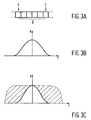
- the low pass characteristics of the convolving function are, however, important and it should be noted that, in relation to Figure 3A, the averaging is performed over the total displacement width. Spatial convolving with a function of the form shown in Figure 3B is spatial low passing.
- the frequency response of the low pass function is shown in Figure 3C in which amplitude (A) is plotted against frequency (f).
- the dotted line represents the available video bandwidth (which depends on the video standard used) and so the difference between the two areas enclosed by the dotted and full lines respectively indicate the extent of lost high frequency information.
- the blur perceived is the result of the spatial low pass which is displacement (and so speed) dependent. When the displacement is large, the averaging will be over more picture elements and so the cut off point of the low pass action will be low. This means a severe loss of high frequency spatial components and thus a lot of blur.
- the blur on time persistent displays can be modelled as a spatial speed dependent low pass filter.
- a video signal enhancement circuit comprising a spatial speed dependent high frequency enhancement filter circuit is incorporated in the display system and used to process the input video signal and modify this signal so as to enhance the spatial frequencies of moving components in the image to be displayed according to the speed of the moving components, and thereby compensate for the low passing.
- the enhancement filter circuit in this embodiment is referenced at 40 and is connected between the input 25 and the synchronisation separator 26 so as to process the incoming video signal, or more precisely, the information content of this signal, and supply enhanced video information signals to the column driver circuit 22 of the display drive circuitry 15.
- the filter ideally should be complementary to the low passing action of the eye and to this end its cut off frequency response is made motion dependent.
- a fully complementary filter is not practical because the restoration of those certain frequencies which have been attenuated to very low levels, e.g. below noise thresholds, could not realistically be achieved.
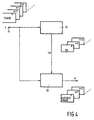
- FIG. 4 is a schematic diagram illustrating the principles of the operation of the main components of an exemplary circuit 40 in a preferred embodiment.
- the circuit in this example comprises a digital motion adaptive spatial filter, MASF, circuit 50 which adjusts its frequency characteristics in accordance with movement on the spatial domain. For slow speeds, no high frequency enhancement takes place. As the speed increases, the cut off point of the filter becomes lower and this results in a speed dependent enhancement. Thus, as the speed becomes higher, the point in the frequency spectrum from which enhancement starts becomes lower.
- MASF digital motion adaptive spatial filter
- the applied video signal V comprising a succession of fields, n, n + 1, n + 2, etc., of video information is supplied to inputs of the motion adaptive spatial filter 50, and a motion estimator 51.
- the motion estimator 51 estimates the motion between successive image fields, and thus speed information. Its output is a displacement field for every image field. Assuming an X-Y coordinate system, this displacement field indicates the displacements in the horizontal and vertical positions, dx , dy , of each pixel, or alternative a block of pixels, from the current field to the next field. Such displacement is one way of providing motion (speed) information. It is expected that the displacement field is as close to the real motion flow as possible.
- An example of a motion estimator and its operation is described in EP-A-0415491.
- the motion estimator 51 can operate on a pixel or block basis to provide motion information output for pixels or blocks respectively.
- Block type motion estimators are more common. If the estimator outputs motion information on a block basis the motion information can be converted to a pixel basis in simple manner if it is assumed that all pixels in the block have the same movement as the block.
- this circuit receives the motion information, Im, from the motion estimator 51.
- the MASF circuit 50 receives the motion information, Im, from the motion estimator 51.
- the MASF circuit 50 then has the information about the contents of a pixel, px , y , as well as the displacement of the pixel from the current field to the next, d p x , d p y .
- filter types There are a number of filter types which can be used. The following description concerns one example used experimentally.
- n x,y are the contents of the pixel located at x , y .
- the averaging process of the eye was assumed for simplicity to be such that equal weights were accorded to the contributory picture elements, that is, the amplitude/time relationship depicted in Figure 3B for convenience is considered to be generally rectangular rather than as shown.
- the new value, n' 0 of the pixel at x , y is calculated using the formula (3). This filter characteristic enhances high frequencies while at low frequencies its gain is unity.
- dx can be an even number then in order to get valid subscripts it is necessary to round it up to the nearest odd number (zero is also considered an even number). Rounding also occurs in order to get an integer value in case the motion estimator supplies displacements to a higher degree of accuracy than just integers.
- n' 0 n 0 + ( n 0 - n - 2 + n - 1 + n 0 + n 1 + n 2 5 )
- the filter characteristic shown in equation (3) is a motion adaptive filter. Its specific characteristics depend on the displacement (motion). For a displacement of 0 or 1 then n' 0 is equal to n 0 . Thus for zero or very low speeds no filtering occurs. As the speed increases the enhancement commences from progressively lower spatial frequencies. This happens because the number of negative terms in the addition "spreads" more and more.
- the modified video signal, V', comprising a succession of filtered fields, obtained from the circuit 50 is passed to the drive circuit 15 which drives the display panel in accordance therewith.
- MASF filter is simple and convenient to implement.
- other examples of motion adaptive filters are known per se and can be used instead.
- other kinds of motion estimators providing motion information in different forms, for example, vectors per block rather than vectors per pixel, may be used.
- FIG. 5 An example circuit configuration of the video signal enhancement circuit 40 for performing the above-described filtering operation is shown schematically in Figure 5.
- the video signal, V is supplied to a speed dependent low pass filter circuit 41 having a low pass characteristic similar to that of the eye and to which the image motion information signal, Im, derived from the motion estimator circuit is also applied.
- the low passing of the eye is simulated to provide a modified signal VIp, and its difference, Vd, from the original signal V is obtained by means of a subtracter circuit 42.
- This difference signal Vd is then added to the original signal V at the adder circuit 43 where it acts in a form of pre-emphasis to provide an enhanced video signal, indicated at V', which is then applied to the display panel drive circuit 15.
- FIG. 6A illustrates the luminance (L) transition from dark, Dk, to bright, Bt, and shows the one dimensional amplitude of the edge.
- VIp simulated low passing
- FIG. 6B Since the low passing is dependent on speed of movement of the edge the effect achieved will be different for different speeds.
- the effects for comparatively high and low speeds are illustrated in Figure 6B by the full and the broken likes respectively.
- the enhancement signal, Vd in Figure 5 is the difference between the signals of Figures 6A and 6B and this difference is depicted in Figure 6C. Again, full and broken lines are used to denote high and low speeds respectively.
- an enhanced video signal, V' is obtained as shown in Figure 6D to give an enhanced edge.
- This, in effect, is the image signal which is presented to the viewer of the display panel 10.
- the enhancement made to the video signal by the circuit 40 compensates for the speed dependent spatial low passing that the viewer's eye performs on moving images displayed on the panel. As a result, the extent of perceived blurring experienced by a viewer when viewing moving images is considerably reduced.
- the effectiveness of the signal enhancement filter circuit is determined by its frequency response characteristic in relation to speed. For low speeds the cut off of the enhancement is selected to be high while for high speeds it is selected to be low. Using a filter circuit with a cut off frequency too low for a given speed results in over enhancement. On the other hand, using a filter circuit with a cut off frequency too high results in under enhancement so that the extent of perceived blurring is virtually unchanged. It is then necessary to have the correct filter characteristic for every speed so that the image is enhanced sufficiently for an improvement to be visible but not so much that the enhancement itself is visible in the form of extreme peaking.
- the circuit 40 need not be located between the input 25 and the circuits 26 and 24 as shown in Figure 1 but could instead be connected, for example, between video processing circuit 24 and the column driver circuit 22 of the display panel drive circuit 15.
- the method of operation can be applied with similar advantageous effects to passive LC display panels and also other kinds of time persistent display panels, for example, electrochromic and electrophoretic type panels.
- the display system may be a projection display system rather than direct view in which case a high intensity projection lamp is employed for the light source.
Landscapes
- Engineering & Computer Science (AREA)
- Multimedia (AREA)
- Signal Processing (AREA)
- Control Of Indicators Other Than Cathode Ray Tubes (AREA)
- Liquid Crystal Display Device Control (AREA)
- Liquid Crystal (AREA)
- Transforming Electric Information Into Light Information (AREA)
Claims (4)
- Matrixtyp-Anzeigesystem zum Anzeigen von Bewegtbildern mit einem Matrix-Anzeigefeld (10) mit Bildelementen (12) in einer Zeilen- und Spaltenanordnung zum Erzeugen von Anzeigeausgaben und mit einer Bildelement-Ansteuerungsschaltung (15) zum Ansteuern der Bildelemente (12) entsprechend einem zugeführten Videosignal (V), das Halbbilder mit Videoinformationen enthält und einem Eingang (25) zugeführt wird, indem die Bildelementzeilen (12) nacheinander in einer Halbbildperiode adressiert werden und die Anordnung der Bildelemente (12) wiederholt in aufeinanderfolgenden Halbbildperioden adressiert wird, wobei die Bildelemente der Anordnung in jeder Halbbildperiode angesteuert werden, um Anzeigeausgaben entsprechend den Videoinformationen des Videosignals (V) zu liefern und ihre Anzeigeausgaben für mindestens einen wesentlichen Teil des Intervalls zwischen aufeinanderfolgenden Adressierungen festzuhalten, wobei die Anzeigeausgaben der in einer Halbbildperiode adressierten Bildelemente (12) der Anordnung Bildpixel in einem durch die Anordnung entsprechend einem Halbbild mit Videoinformationen des Videosignals (V) erzeugten Anzeigebild darstellen, wobei das System eine Filterschaltung (40) enthält, durch die die Videoinformationen des Videosignals (V) von dem genannten Eingang (25) der Filterschaltung (40) der Bildelement-Ansteuerungsschaltung (15) zugeführt werden, wobei die Filterschaltung (40) Bewegungsschätzungsmittel (51) enthält, denen die Videoinformationen des Videosignals (V) zugeführt werden, dadurch gekennzeichnet, dass die Filterschaltung (40) eine geschwindigkeitshabhängige Verstärkungsfilterschaltung für hohe Raumfrequenzen (40) ist und die Bewegungsschätzungsmittel (51) ein Verschiebungs-Halbbild, das die Verschiebung der Bildpixel für Anzeigebilder von einem Halbbild zum nächsten Halbbild darstellt, sowie ein Ausgabesignal liefern, das Informationen (Im) enthält, welche einen Hinweis auf die Bewegungsgeschwindigkeit der Bildpixel in aufeinanderfolgenden Anzeigebildern geben, und wobei die Filterschaltung (40) weiterhin eine geschwindigkeitsabhängige Tiefpassfilterschaltung (41) umfasst, der das Videosignal (V) und das Ausgangssignal der Bewegungsschätzungsmittel (51) zugeführt werden, wobei die geschwindigkeitsabhängige Tiefpassfilterschaltung (41), die das Videosignal (V) filtert, einen Grenzpunkt hat, der in dem Maße, wie die Geschwindigkeit der Bildpixelbewegung zunimmt, niedriger wird, und wobei die Verstärkungsfilterschaltung für hohe Raumfrequenzen (40) eine Subtrahierschaltung (42) zum Erzeugen eines Verstärkungssignals (Vd) entsprechend der Differenz zwischen dem Ausgangssignal (Vlp) der geschwindigkeitsabhängigen Tiefpassfilterschaltung und dem Videosignal (V) sowie eine Addierschaltung (43) enthält, in der das Verstärkungssignal (Vd) zu dem Videosignal (V) addiert wird, um ein modifiziertes Videosignal (V') zu liefern, in dem die Raumfrequenzen von sich bewegenden Bildpixeln in Anzeigebildern entsprechend ihrer Bewegungsgeschwindigkeit verstärkt sind und das der Bildelement-Ansteuerungsschaltung (15) zugeführt wird.
- Matrix-Anzeigesystem nach Anspruch 1, dadurch gekennzeichnet, dass das Matrix-Anzeigefeld (10) ein Flüssigkristall-Anzeigefeld mit aktiver Matrix umfasst.
- Verfahren zum Betrieb eines Matrixtyp-Anzeigesystems der Art, die ein Matrix-Anzeigefeld (10) mit Bildelementen (12) in einer Zeilen- und Spaltenanordnung enthält, um Bewegtbilder entsprechend einem Videosignal (V) anzuzeigen, das Halbbilder mit Videoinformationen enthält, wobei in diesem Verfahren die Bildelemente (12) in der Anordnung in aufeinander folgenden Halbbildperioden angesteuert werden, um Anzeigeausgaben entsprechend den Videoinformationen des Videosignals (V) zu liefern, indem die Bildelementzeilen nacheinander wiederholt adressiert werden, um eine Folge von Anzeigebildern zu erzeugen, und wobei in diesem Verfahren die Bildelemente (12) ihre Anzeigeausgaben nach der Adressierung für mindestens einen wesentlichen Teil einer Halbbildperiode festhalten, wobei die Anzeigeausgaben der in einer Halbbildperiode adressierten Bildelemente (12) der Anordnung Bildpixel in einem durch die Anordnung entsprechend einem Halbbild mit Videoinformationen des Videosignals (V) erzeugten Anzeigebild darstellen, wobei das Videosignal ((V) einer Filteroperation (40) unterzogen wird, bevor es den Bildelementen (12) des Matrix-Anzeigefelds (10) zugeführt wird, dadurch gekennzeichnet, dass die Filteroperation (40) eine geschwindigkeitshabhängige Verstärkungsfilteroperation für hohe Raumfrequenzen (40) ist, um die Raumfrequenzen der sich bewegenden Bildpixel in den Anzeigebildern entsprechend der Bewegungsgeschwindigkeit der Anzeigepixel zu verstärken, wobei Verschiebungs-Halbbilder, die die Verschiebung der Bildpixel für Anzeigebilder von einem Halbbild zum nächsten Halbbild darstellen, erzeugt werden und Informationen (Im), welche einen Hinweis auf die Bewegungsgeschwindigkeit der Bildpixel in aufeinanderfolgenden Anzeigebildern geben, daraus abgeleitet werden, und wobei das Videosignal (V) durch einen geschwindigkeitsabhängigen Tiefpassfilter (41) gefiltert wird, der entsprechend den Informationen (Im), die einen Hinweis auf die Bewegungsgeschwindigkeit der Bildpixel in aufeinanderfolgenden Anzeigebildern geben, gesteuert wird, so dass sein Grenzpunkt in dem Maße niedriger wird, wie die Geschwindigkeit der Bildpixelbewegung zunimmt, und wobei ein Verstärkungssignal (Vd), das die Differenz zwischen dem gefilterten Videosignal (Vlp), das von dem geschwindigkeitsabhängigen Tiefpassfilter geliefert wird, und dem Videosignal (V) darstellt, zu dem Videosignal (V) addiert wird, um ein verstärktes Videosignal (V') zu liefern, das den Bildelementen (12) zugeführt wird.
- Verfahren nach Anspruch 3, dadurch gekennzeichnet, dass das Matrix-Anzeigefeld (10) ein Flüssigkristall-Anzeigefeld mit aktiver Matrix umfasst.
Applications Claiming Priority (2)
| Application Number | Priority Date | Filing Date | Title |
|---|---|---|---|
| GB9325302 | 1993-12-10 | ||
| GB939325302A GB9325302D0 (en) | 1993-12-10 | 1993-12-10 | Matrix video display systems and methods of operating such systems |
Publications (3)
| Publication Number | Publication Date |
|---|---|
| EP0657860A2 EP0657860A2 (de) | 1995-06-14 |
| EP0657860A3 EP0657860A3 (de) | 1997-02-05 |
| EP0657860B1 true EP0657860B1 (de) | 2004-11-17 |
Family
ID=10746401
Family Applications (1)
| Application Number | Title | Priority Date | Filing Date |
|---|---|---|---|
| EP19940203525 Expired - Lifetime EP0657860B1 (de) | 1993-12-10 | 1994-12-05 | Matrixtyp-Videosichtgerät mit geschwindigkeitsabhängigem Filter zur Steigerung der hohen Raumfrequenzen und Verfahren zu dessen Betrieb |
Country Status (4)
| Country | Link |
|---|---|
| EP (1) | EP0657860B1 (de) |
| JP (1) | JPH07199856A (de) |
| DE (1) | DE69434133T2 (de) |
| GB (1) | GB9325302D0 (de) |
Cited By (2)
| Publication number | Priority date | Publication date | Assignee | Title |
|---|---|---|---|---|
| US7643019B2 (en) | 2002-05-23 | 2010-01-05 | Koninklijke Philips Electronics N.V. | Edge dependent motion blur reduction |
| US8194994B2 (en) | 2007-03-19 | 2012-06-05 | Sony Deutschland Gmbh | Apparatus and method for reducing motion blur in a video signal |
Families Citing this family (15)
| Publication number | Priority date | Publication date | Assignee | Title |
|---|---|---|---|---|
| US6163308A (en) * | 1997-08-08 | 2000-12-19 | Philips Electronics North America Corporation | Method and apparatus for minimizing visual artifacts caused by the pixel display of a video image |
| JP3305240B2 (ja) * | 1997-10-23 | 2002-07-22 | キヤノン株式会社 | 液晶表示パネル駆動装置と駆動方法 |
| CN1237783C (zh) | 2001-06-18 | 2006-01-18 | 皇家菲利浦电子有限公司 | 防运动模糊显示器 |
| KR100985026B1 (ko) * | 2002-05-28 | 2010-10-04 | 코닌클리케 필립스 일렉트로닉스 엔.브이. | 영상의 모션 블러, 플리커 및 밝기 손실을 감소시키기 위한 방법, 비-스트로보스코픽 디스플레이 디바이스 |
| JP4451057B2 (ja) * | 2002-12-27 | 2010-04-14 | シャープ株式会社 | 表示装置の駆動方法、表示装置、および、そのプログラム |
| FR2857147A1 (fr) * | 2003-07-01 | 2005-01-07 | Thomson Licensing Sa | Procede de traitement d'une sequence d'images video dans un panneau d'affichage a cristaux liquides |
| EP1702457B1 (de) * | 2003-12-01 | 2009-08-26 | Koninklijke Philips Electronics N.V. | Bewegungskompensierte invers-filterung mit bandpassfiltern für die bewegungsverschmierungsreduktion |
| WO2006016454A1 (ja) * | 2004-08-11 | 2006-02-16 | Sony Corporation | 画像処理装置および方法、記録媒体、並びにプログラム |
| WO2006040722A2 (en) * | 2004-10-13 | 2006-04-20 | Koninklijke Philips Electronics N.V. | Display time control for moving images |
| JP2006243283A (ja) * | 2005-03-02 | 2006-09-14 | Sony Corp | 照明装置及び表示装置 |
| KR101182298B1 (ko) | 2005-09-12 | 2012-09-20 | 엘지디스플레이 주식회사 | 액정 표시장치의 구동장치 및 구동방법 |
| KR100731048B1 (ko) | 2005-10-20 | 2007-06-22 | 엘지.필립스 엘시디 주식회사 | 액정 표시장치의 구동장치 및 구동방법 |
| KR100769195B1 (ko) | 2006-02-09 | 2007-10-23 | 엘지.필립스 엘시디 주식회사 | 액정 표시장치의 구동장치 및 구동방법 |
| WO2007116370A1 (en) * | 2006-04-11 | 2007-10-18 | Koninklijke Philips Electronics N.V. | 1d motion compensated dynamic frame insertion |
| US8908100B2 (en) | 2007-12-28 | 2014-12-09 | Entropic Communications, Inc. | Arrangement and approach for motion-based image data processing |
Family Cites Families (3)
| Publication number | Priority date | Publication date | Assignee | Title |
|---|---|---|---|---|
| US5119084A (en) * | 1988-12-06 | 1992-06-02 | Casio Computer Co., Ltd. | Liquid crystal display apparatus |
| JPH0363692A (ja) * | 1989-08-01 | 1991-03-19 | Sharp Corp | 表示装置の駆動回路 |
| JP2768548B2 (ja) * | 1990-11-09 | 1998-06-25 | シャープ株式会社 | パネルディスプレイ表示装置 |
-
1993
- 1993-12-10 GB GB939325302A patent/GB9325302D0/en active Pending
-
1994
- 1994-12-05 DE DE1994634133 patent/DE69434133T2/de not_active Expired - Fee Related
- 1994-12-05 EP EP19940203525 patent/EP0657860B1/de not_active Expired - Lifetime
- 1994-12-09 JP JP30643394A patent/JPH07199856A/ja active Pending
Cited By (2)
| Publication number | Priority date | Publication date | Assignee | Title |
|---|---|---|---|---|
| US7643019B2 (en) | 2002-05-23 | 2010-01-05 | Koninklijke Philips Electronics N.V. | Edge dependent motion blur reduction |
| US8194994B2 (en) | 2007-03-19 | 2012-06-05 | Sony Deutschland Gmbh | Apparatus and method for reducing motion blur in a video signal |
Also Published As
| Publication number | Publication date |
|---|---|
| EP0657860A2 (de) | 1995-06-14 |
| DE69434133T2 (de) | 2006-06-29 |
| DE69434133D1 (de) | 2004-12-23 |
| JPH07199856A (ja) | 1995-08-04 |
| GB9325302D0 (en) | 1994-02-16 |
| EP0657860A3 (de) | 1997-02-05 |
Similar Documents
| Publication | Publication Date | Title |
|---|---|---|
| EP0657860B1 (de) | Matrixtyp-Videosichtgerät mit geschwindigkeitsabhängigem Filter zur Steigerung der hohen Raumfrequenzen und Verfahren zu dessen Betrieb | |
| EP1927974B1 (de) | Flüssigkristallanzeige mit bereichsanpassbarem Rücklicht | |
| JP4966015B2 (ja) | 動きボケ低減のための帯域通過フィルタを用いた動き補償逆フィルタリング | |
| KR100485557B1 (ko) | 표시 장치 | |
| CN100345035C (zh) | 图像显示装置 | |
| KR100892228B1 (ko) | 안티 움직임 흐림 디스플레이 | |
| EP0741898B1 (de) | Flüssigkristallanzeigegerät mit aktiver matrix und steurungsverfahren dafür zur kompensation von übersprechen | |
| US5912651A (en) | Matrix display systems and methods of operating such systems | |
| US20110007050A1 (en) | Image display apparatus and image display method | |
| EP2409194B1 (de) | Anzeige mit bereichsadaptiver hinterleuchtung und verfahren dafür mit berechnungs- und halo-artefakt-reduzierung | |
| US7708407B2 (en) | Eye tracking compensated method and device thereof | |
| US20120081419A1 (en) | Image display apparatus and control method thereof | |
| KR100905986B1 (ko) | 디스플레이 장치의 극성을 인터리빙하여 깜박임을저감하는 방법 및 시스템 | |
| JPH09329805A (ja) | 液晶表示装置 | |
| US20090002559A1 (en) | Phase Shift Insertion Method For Reducing Motion Artifacts On Hold-Type Displays | |
| EP2048649A1 (de) | Bildverarbeitungseinrichtung und bildverarbeitungsverfahren | |
| KR101422600B1 (ko) | 모션블러를 제거한 액정표시장치 및 이의 구동방법 | |
| US8289252B2 (en) | Liquid crystal display device including a data analysis unit and method for driving the same | |
| JP2002182620A (ja) | 画像表示装置及び画像表示方法 | |
| Har-Noy et al. | Filter banks for improved LCD motion | |
| JP2003015108A (ja) | 映像表示装置及び映像表示方法 | |
| Terazawa et al. | Application of an interlaced scan driving method to TFT-LCD | |
| JPH1039274A (ja) | 液晶表示パネルの駆動装置 | |
| Fergason et al. | Application of time-based multiplexing to LCD projection displays |
Legal Events
| Date | Code | Title | Description |
|---|---|---|---|
| PUAI | Public reference made under article 153(3) epc to a published international application that has entered the european phase |
Free format text: ORIGINAL CODE: 0009012 |
|
| AK | Designated contracting states |
Kind code of ref document: A2 Designated state(s): DE FR GB NL |
|
| PUAL | Search report despatched |
Free format text: ORIGINAL CODE: 0009013 |
|
| AK | Designated contracting states |
Kind code of ref document: A3 Designated state(s): DE FR GB NL |
|
| 17P | Request for examination filed |
Effective date: 19970805 |
|
| 17Q | First examination report despatched |
Effective date: 19990823 |
|
| GRAP | Despatch of communication of intention to grant a patent |
Free format text: ORIGINAL CODE: EPIDOSNIGR1 |
|
| RTI1 | Title (correction) |
Free format text: MATRIX VIDEO DISPLAY SYSTEM HAVING A SPEED-DEPENDENT FILTER TO ENHANCE THE HIGH SPATIAL FREQUENCIES AND METHOD OF OPERATI |
|
| GRAS | Grant fee paid |
Free format text: ORIGINAL CODE: EPIDOSNIGR3 |
|
| GRAA | (expected) grant |
Free format text: ORIGINAL CODE: 0009210 |
|
| AK | Designated contracting states |
Kind code of ref document: B1 Designated state(s): DE FR GB NL |
|
| PG25 | Lapsed in a contracting state [announced via postgrant information from national office to epo] |
Ref country code: NL Free format text: LAPSE BECAUSE OF FAILURE TO SUBMIT A TRANSLATION OF THE DESCRIPTION OR TO PAY THE FEE WITHIN THE PRESCRIBED TIME-LIMIT Effective date: 20041117 |
|
| REG | Reference to a national code |
Ref country code: GB Ref legal event code: FG4D |
|
| REF | Corresponds to: |
Ref document number: 69434133 Country of ref document: DE Date of ref document: 20041223 Kind code of ref document: P |
|
| NLV1 | Nl: lapsed or annulled due to failure to fulfill the requirements of art. 29p and 29m of the patents act | ||
| PLBE | No opposition filed within time limit |
Free format text: ORIGINAL CODE: 0009261 |
|
| STAA | Information on the status of an ep patent application or granted ep patent |
Free format text: STATUS: NO OPPOSITION FILED WITHIN TIME LIMIT |
|
| ET | Fr: translation filed | ||
| 26N | No opposition filed |
Effective date: 20050818 |
|
| PGFP | Annual fee paid to national office [announced via postgrant information from national office to epo] |
Ref country code: DE Payment date: 20060214 Year of fee payment: 12 |
|
| PGFP | Annual fee paid to national office [announced via postgrant information from national office to epo] |
Ref country code: GB Payment date: 20061218 Year of fee payment: 13 |
|
| PG25 | Lapsed in a contracting state [announced via postgrant information from national office to epo] |
Ref country code: DE Free format text: LAPSE BECAUSE OF NON-PAYMENT OF DUE FEES Effective date: 20070703 |
|
| PGFP | Annual fee paid to national office [announced via postgrant information from national office to epo] |
Ref country code: FR Payment date: 20061227 Year of fee payment: 13 |
|
| GBPC | Gb: european patent ceased through non-payment of renewal fee |
Effective date: 20071205 |
|
| REG | Reference to a national code |
Ref country code: FR Ref legal event code: ST Effective date: 20081020 |
|
| PG25 | Lapsed in a contracting state [announced via postgrant information from national office to epo] |
Ref country code: GB Free format text: LAPSE BECAUSE OF NON-PAYMENT OF DUE FEES Effective date: 20071205 |
|
| PG25 | Lapsed in a contracting state [announced via postgrant information from national office to epo] |
Ref country code: FR Free format text: LAPSE BECAUSE OF NON-PAYMENT OF DUE FEES Effective date: 20071231 |