EP0658431A2 - Farbstoffhöhe-messvorrichtung in einem Tintenstrahldrucker - Google Patents
Farbstoffhöhe-messvorrichtung in einem Tintenstrahldrucker Download PDFInfo
- Publication number
- EP0658431A2 EP0658431A2 EP94309304A EP94309304A EP0658431A2 EP 0658431 A2 EP0658431 A2 EP 0658431A2 EP 94309304 A EP94309304 A EP 94309304A EP 94309304 A EP94309304 A EP 94309304A EP 0658431 A2 EP0658431 A2 EP 0658431A2
- Authority
- EP
- European Patent Office
- Prior art keywords
- ink
- reservoir
- electrodes
- level
- volume
- Prior art date
- Legal status (The legal status is an assumption and is not a legal conclusion. Google has not performed a legal analysis and makes no representation as to the accuracy of the status listed.)
- Granted
Links
- 238000007641 inkjet printing Methods 0.000 title claims abstract description 9
- 239000000463 material Substances 0.000 claims description 14
- 238000000034 method Methods 0.000 claims description 5
- 239000002657 fibrous material Substances 0.000 claims description 4
- 239000002184 metal Substances 0.000 claims description 4
- 229910052751 metal Inorganic materials 0.000 claims description 4
- 239000004753 textile Substances 0.000 claims description 4
- 239000004020 conductor Substances 0.000 claims description 2
- 238000007650 screen-printing Methods 0.000 claims description 2
- 239000010409 thin film Substances 0.000 claims 1
- 238000007639 printing Methods 0.000 abstract description 8
- 238000005259 measurement Methods 0.000 abstract description 4
- 230000011664 signaling Effects 0.000 abstract 1
- 239000000976 ink Substances 0.000 description 78
- 238000001514 detection method Methods 0.000 description 5
- 239000000835 fiber Substances 0.000 description 4
- XUIMIQQOPSSXEZ-UHFFFAOYSA-N Silicon Chemical compound [Si] XUIMIQQOPSSXEZ-UHFFFAOYSA-N 0.000 description 3
- 230000002745 absorbent Effects 0.000 description 3
- 239000002250 absorbent Substances 0.000 description 3
- 230000006870 function Effects 0.000 description 3
- 229910052710 silicon Inorganic materials 0.000 description 3
- 239000010703 silicon Substances 0.000 description 3
- 238000007651 thermal printing Methods 0.000 description 3
- 238000013461 design Methods 0.000 description 2
- 238000003780 insertion Methods 0.000 description 2
- 230000037431 insertion Effects 0.000 description 2
- 229920000728 polyester Polymers 0.000 description 2
- 229920002799 BoPET Polymers 0.000 description 1
- RYGMFSIKBFXOCR-UHFFFAOYSA-N Copper Chemical compound [Cu] RYGMFSIKBFXOCR-UHFFFAOYSA-N 0.000 description 1
- 239000005041 Mylar™ Substances 0.000 description 1
- 239000004952 Polyamide Substances 0.000 description 1
- 239000004743 Polypropylene Substances 0.000 description 1
- 239000004772 Sontara Substances 0.000 description 1
- 230000003466 anti-cipated effect Effects 0.000 description 1
- 238000006243 chemical reaction Methods 0.000 description 1
- 230000006835 compression Effects 0.000 description 1
- 238000007906 compression Methods 0.000 description 1
- 229910052802 copper Inorganic materials 0.000 description 1
- 239000010949 copper Substances 0.000 description 1
- 238000005868 electrolysis reaction Methods 0.000 description 1
- 239000012535 impurity Substances 0.000 description 1
- 239000000203 mixture Substances 0.000 description 1
- 238000012986 modification Methods 0.000 description 1
- 230000004048 modification Effects 0.000 description 1
- 230000000149 penetrating effect Effects 0.000 description 1
- 229920002647 polyamide Polymers 0.000 description 1
- 229920001155 polypropylene Polymers 0.000 description 1
- 230000008569 process Effects 0.000 description 1
- 230000009467 reduction Effects 0.000 description 1
- 230000003252 repetitive effect Effects 0.000 description 1
- 230000004044 response Effects 0.000 description 1
- 230000000630 rising effect Effects 0.000 description 1
- 229910001220 stainless steel Inorganic materials 0.000 description 1
- 239000010935 stainless steel Substances 0.000 description 1
- 239000000126 substance Substances 0.000 description 1
- 229920002994 synthetic fiber Polymers 0.000 description 1
- 238000012360 testing method Methods 0.000 description 1
Images

Classifications
-
- B—PERFORMING OPERATIONS; TRANSPORTING
- B41—PRINTING; LINING MACHINES; TYPEWRITERS; STAMPS
- B41J—TYPEWRITERS; SELECTIVE PRINTING MECHANISMS, i.e. MECHANISMS PRINTING OTHERWISE THAN FROM A FORME; CORRECTION OF TYPOGRAPHICAL ERRORS
- B41J2/00—Typewriters or selective printing mechanisms characterised by the printing or marking process for which they are designed
- B41J2/005—Typewriters or selective printing mechanisms characterised by the printing or marking process for which they are designed characterised by bringing liquid or particles selectively into contact with a printing material
- B41J2/01—Ink jet
- B41J2/17—Ink jet characterised by ink handling
- B41J2/175—Ink supply systems ; Circuit parts therefor
- B41J2/17566—Ink level or ink residue control
Definitions
- the present invention relates to a measuring apparatus for the ink-level in ink-jet printing unit and more particularly to a measuring apparatus for the ink-level in an ink-jet thermal printing unit comprising an ink-jet thermal printing head integral with the reservoir which is repeatedly rechargeable, whenever the ink has dropped to a pre-determined volume.
- the recharging may be carried out by means of a syringe, or by means of a small capacity cartridge compared with that of the reservoir, as described in European patent application N° 943006684.5 in the name of the applicant.
- End of ink detection apparatus are known in the state of the art for printing units and more generally for units with an ink-jet printing head.
- US patent N° 4 183 029 describes a detection apparatus showing the end of ink flow in the duct between the reservoir and the printing-head, due to an obstruction therein, caused by an air bubble or an impurity.
- US patent N° 5 051 759 describes an ink-end detector, in which two electrodes are fitted in the sponge located in the reservoir and impregnated with ink. The electrodes are connected to a detector circuit that measures the electrical resistance of the ink placed between the electrodes. As known, as the ink is consumed, the sponge progressively empties from one end to the other where the electrodes are fitted. However the ink resistance does not vary extensively until the level of the ink reaches the zone of the electrodes, then rapidly increases thereafter.
- US patent N° 5 136 305 describes a similar end of ink detector, whereby a thermistor is inserted into the sponge, in contact with the ink and receiving a d.c. supply. Measurement of the temperature increase of the thermistor represents the reduction in volume of ink in the sponge.
- US patent N° 5 162 817 describes an end of ink detector for an ink-jet printing head fed by a replaceable cartridge.
- the head comprises its own reservoir complete with an ink-impregnated sponge, onto which the cartridge can be coupled.
- the detector comprises three electrodes fitted in the sponge and selected in pairs for detection with the head in the horizontal or the vertical position.
- European patent application N° 440 110 describes another end of ink detector for an ink-jet printer wherein the reservoir containing an ink-impregnated sponge can be replaced and connected to the head by means of a hollow needle penetrating the reservoir.
- the reservoir has two electrodes, one fitted in the sponge, and the other inserted in the feed duct to the head.
- the detection circuit comprises a compensation resistance for the ink-viscosity according to the temperature.
- Such apparatus are nevertheless not able to indicate continuous variations in the quantity of ink contained in the reservoir in an intermediate zone between minimum and maximum ink content.
- Preferred embodiments of the present invention thus may comprise means to measure the ink-level in a rechargeable unit, able to signal at least one of the extremes, preferably the lower end of an ink-volume variation range, comprised between the minimum remaining volume and the maximum available volume in the reservoir, thus allowing with sufficient precision to determine the moment when the reservoir needs refill with a predetermined volume of ink.
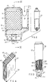
- Fig. 2 represents, as a non-restrictive application example of the invention, a rechargeable printing unit 10 of the type described in the European patent application N° 94306684.5 in the name of the Applicant, which consists of a main structure 11, comprising a reservoir 12 for the ink and an auxiliary structure 16 integral with the main structure 11 and comprising an aperture 18 to admit the refill cartridge 20, inserted in the aperture 18 when the ink in the reservoir 12 has reached a predetermined minimum level.
- the reservoir 12 is defined at the bottom by a wall 14 on the outer face 22 of which an ink-jet thermal printing head 24 is mounted.
- the print-head consists of an integrated circuit technique silicon chip, including a plurality of nozzles 25, the relevant emission chambers and relevant emission resistors, not visible in the figure.
- a feed chamber 28 is located closed at the top by a diaphragm 30 permeable to the ink, but not to air, and communicating with the print-head 24 through a duct 31 passing through a bottom wall 14.
- the reservoir 12 is filled with absorbent material 34 such as for instance a fibre or felt agglomerate, or a pack of layers of non woven textile (TNT), which is impregnated with ink at the time of assembly of the unit.
- absorbent material 34 such as for instance a fibre or felt agglomerate, or a pack of layers of non woven textile (TNT), which is impregnated with ink at the time of assembly of the unit.
- the reservoir 12 After filling with ink, the reservoir 12 is closed in a stable manner with a cover 35 having an aperture 37 to vent the reservoir 12 to atmospheric pressure.
- the absorbent material 34 consists of a pack of sheets or layers of non-woven textile, a material known in the state of the art, and sold under various names according to the nature of the base material, as for instance:
- These materials consist of one or several layers of synthetic fibre placed at random one on top of the other, and bonded together at contact points, so as to form a flat structure like a sheet.
- the sheets cut to the required dimensions are stacked in clearly defined numbers, so as to form a pack which is then inserted into the reservoir 12; as an alterative the pack may be obtained by folding like an accordion a sheet of the material of the required height.
- the number of layers forming the pack must be accurately defined, since any variation of that number (for a same thickness of sheet) produces a greater or lesser level of fibre compression and of consequent control over the resultant capillarity.
- a layer of slightly compressed spongy material 36 is inserted, intended to ensure the flow of ink towards the chamber 28, through the diaphragm 30, by its capillarity.
- the duration of the ink is notably shorter than the life of the print-head 24.
- the printing unit 10 is arranged so as to admit a refill cartridge 20, easily inserted to recharge the reservoir 12 with new ink, and easily removable when the refilling is completed.
- two metal plates 40, 41 are placed in the reservoir 12 (Figs. 3 & 4) against respectively opposing walls 43, 44 and including between them the pack 34 of fibrous material.
- the size of plates 40, 41 is such as to cover completely the end faces of the pack 34 (Fig. 4) and serve as electrodes in contact with the ink to detect the level of ink contained in the reservoir 12, as will be explained further on, and may be made of stainless steel or gold-plated copper, or any other electrically conductive material which withstands chemical attack by the ink.
- the electrodes 40, 41 may also be designed as a sufficiently close-meshed grid, or netting or mesh of one of the previously defined materials.
- a block (Fig. 4) is firstly prepared, consisting of pack 34 included between the electrodes 40, 41, cut to measure in such a manner as to allow its easy single-operation insertion into the reservoir.
- Each of the electrodes 40, 41 has a fin 46 projecting outside the reservoir 12 (Fig. 3) forming an electrical terminal for connection to a detection circuit (Fig. 6) described further on.
- Fig. 5 shows a different embodiment of the electrodes 40,41, designed in the form of a flexible film (flat cable) 48 on which two metal zones 50, 51 are deposited each connected to an electrical terminal 46 and extending in such a manner as to be superimposed completely over the end faces of the fibre pack 34.
- the film 48 may consist for instance of MYLAR (Registered trademark) or some other material having the same properties.
- the film 48 is folded at right angles to match lines 55 & 56 then wound onto pack 34 so as to fully superimpose the metal zones 50, 51 on opposing faces of the pack 34.
- the distance between lines 55, 56 obviously coincides with the thickness H (Fig. 4) of the pack 34.
- the group consisting of the pack 34 and film 48 is then inserted into the reservoir 12.
- the electrodes 40, 41 may be produced by silk-screen printing technique featuring a layer of electrically conductive and chemically inert material deposited on the inner face of two opposing walls 43, 44 of the reservoir 12.
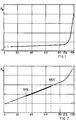
- the electrical resistance R k of the ink being such as to cover the whole of the volume of ink contained in the pack 34 and fully interposed between electrodes 40, 41.
- the resistance R k varies in inverse proportion with the volume (or with the ink level, assuming an equal section) according to a sufficiently accurate law for up to about 80% of the ink contained in the reservoir 12.
- the abscissae S% represent the % consumption of the total ink in the reservoir.
- ink resistance variations show no significant hysteresis, and measurement of the ink level can be repeated several times with good accuracy.
- a small size printing unit i.e. capable of containing 5-6 cm3 of ink and rechargeable by way of a cartridge, as shown in Fig. 2, to ensure a degree of repetitive and constant filling, it has been found that refilling with new ink can be suitably effected when the ink consumption S% has reached approximately 2/3 (66%) of the available ink in the reservoir 12 (Fig.7), or in other words when a minimum quantity of 25% to 40% of ink remains in the reservoir and preferably of the order of 33% of the maximum admissible volume.
- the volume of ink which can be added in an optimum manner i.e. in the shortest possible time and uniformly impregnating the absorbent material 34, is of the order of 1/3 of the total, viz. approximately 2 cm3.
- Two resistances Rs and Rt in series form a resistive voltage divider connected between the supply voltage V and earth M.
- An intermediate point P between the two resistors is connected to a first input 61 of a switch 60.
- a second input 62 of the switch 60 is connected at a point A to one of the two electrodes, for instance to electrode 40.
- the other electrode 41 is connected to earth M through a transistor T, which connects electrode 41 to earth for brief moments only, in response to a signal S, to avoid any ink electrolysis phenomenon.
- the first electrode 40 is also connected at point A to a resistor Re in turn connected to the voltage supply V.
- Resistor Re functions as a balancing and compensation resistance for several resistance values of differing inks, as may be seen further on.
- the switch 60 is connected to an analog/digital converter (A/D) 64 which in turn is connected by a bus 66 to a microprocessor 68.
- A/D analog/digital converter
- the switch 60 is preferably integrated, together with the A/D converter 64 and the microprocessor 68, in a single integrated circuit chip 70.
- the microprocessor 68 processes the voltage values recorded at points P and A each time the transistor T is activated by the signal S from the microprocessor 68.
- the apparatus according to the invention is preset to allow for the said variations and compensate them as described further on.
- the resistivity variation versus the temperature is mainly caused by the differing ionic mobility of the ink base solution, as represented by a typical temperature coefficient "ct", which, as an example, may be: 0.013 in the temperature range between 10 and 60°C.
- the resistor Rt is therefore preferably a thermistor having the same temperature coefficient "ct" as the ink, so that the voltage at point P (threshold value) also varies with the temperature.
- the resistor Rt is compensated after assigning a specific value to the resistance Re.
- the resistivity of a given type of ink measured between electrodes 40, 41 is 100 ohms when the reservoir is full, whilst after consumption of approximately 2/3 of the total, that resistivity has increased to 500 ohms.
- a resistor Re with a value of 500 ohms, is then selected for that type of ink, so that, when the ink level has dropped to the value shown above, the voltage at point A being V/2.
- the resistor Re may have, of course, other values allocated to it, without limiting the scope of the present invention.
- the resistor Re may be directly integrated in the print-head 24 silicon chip, as well as emission resistors R1, R2,...Ri (Fig. 6). In that case, since a terminal C of resistor Re is connected to the supply V, the common supply track D, already present in the print-head 24 silicon chip, can save an external connection.
- the microprocessor 68 records the voltage value at point A and, after triggering switching of the switch 60, proceeds with a comparison with the voltage at point P, already temperature-compensated by resistance Rt. As soon as the voltage at point A reaches the anticipated value V/2, the microprocessor generates a signal non-specifically shown here, to activate an alarm apparatus in a known manner, to indicate to the operator that the ink supply must be refilled.
- the resistor Rt may be a normal temperature sensor disassociated from the particular value of the ink temperature coefficient "ct" and fixed to the printing unit 10 as nearest as possible to the print-head 24.
- the microprocessor 68 records the temperature of the ink and, using a conversion table stored in part of the memory M of the microprocessor 68, calculates an equivalent threshold voltage, to which the voltage at point A is compared.
Landscapes
- Ink Jet (AREA)
- Measurement Of Levels Of Liquids Or Fluent Solid Materials (AREA)
Applications Claiming Priority (2)
| Application Number | Priority Date | Filing Date | Title |
|---|---|---|---|
| ITTO930953 | 1993-12-16 | ||
| ITTO930953A IT1272076B (it) | 1993-12-16 | 1993-12-16 | Dispositivo di misura del livello di inchiostro di un modulo di stampaa getto di inchiostro |
Publications (3)
| Publication Number | Publication Date |
|---|---|
| EP0658431A2 true EP0658431A2 (de) | 1995-06-21 |
| EP0658431A3 EP0658431A3 (de) | 1996-06-26 |
| EP0658431B1 EP0658431B1 (de) | 2000-05-17 |
Family
ID=11411935
Family Applications (1)
| Application Number | Title | Priority Date | Filing Date |
|---|---|---|---|
| EP94309304A Expired - Lifetime EP0658431B1 (de) | 1993-12-16 | 1994-12-13 | Farbstoffhöhe-messvorrichtung in einem Tintenstrahldrucker |
Country Status (5)
| Country | Link |
|---|---|
| US (1) | US5623291A (de) |
| EP (1) | EP0658431B1 (de) |
| JP (1) | JP3513239B2 (de) |
| DE (1) | DE69424513T2 (de) |
| IT (1) | IT1272076B (de) |
Cited By (3)
| Publication number | Priority date | Publication date | Assignee | Title |
|---|---|---|---|---|
| FR2765330A1 (fr) * | 1997-06-27 | 1998-12-31 | Canon Kk | Dispositif de determination d'une quantite de produit consommable, notamment de l'encre presente dans un reservoir a plusieurs compartiments et dispositif d'impression de documents correspondant |
| EP0940259A3 (de) * | 1998-03-04 | 1999-11-17 | Hewlett-Packard Company | Elektrische Erneuerung für Tintenzuführsystem |
| US6137512A (en) * | 1994-07-06 | 2000-10-24 | Canon Kabushiki Kaisha | Ink container |
Families Citing this family (24)
| Publication number | Priority date | Publication date | Assignee | Title |
|---|---|---|---|---|
| JP3039358B2 (ja) * | 1996-02-21 | 2000-05-08 | 富士ゼロックス株式会社 | インク供給装置および記録装置 |
| US6106087A (en) * | 1996-10-01 | 2000-08-22 | Brother Kogyo Kabushiki Kaisha | Detection apparatus for detecting residual ink quantity in ink cartridge |
| US6095643A (en) * | 1998-05-07 | 2000-08-01 | Lexmark International, Inc. | Refillable disposable inkjet cartridge with foam-filled and free ink reservoirs |
| JP3450798B2 (ja) * | 1999-04-27 | 2003-09-29 | キヤノン株式会社 | 液体供給システム、該システムに用いられる液体収納容器、該システムを用いたインクジェットヘッドカートリッジ |
| JP2001001544A (ja) * | 1999-06-24 | 2001-01-09 | Canon Inc | 液体供給方法、液体供給容器、負圧発生部材収納容器及び液体収納容器 |
| US6431670B1 (en) * | 2000-02-14 | 2002-08-13 | Hewlett-Packard Company | Ink level sensing method and apparatus |
| EP1164022B1 (de) * | 2000-06-16 | 2008-07-30 | Canon Kabushiki Kaisha | Tintenstrahlaufzeichnungsgerät das ein Festkörperhalbleiterbauelement verwendet |
| US6412894B1 (en) | 2001-01-19 | 2002-07-02 | Lexmark International, Inc. | Ink cartridge and method for determining ink volume in said ink cartridge |
| CN1198731C (zh) * | 2001-05-17 | 2005-04-27 | 精工爱普生株式会社 | 墨盒及向其内注墨的方法 |
| US6663234B2 (en) * | 2001-06-11 | 2003-12-16 | Xerox Corporation | Ink cartridge providing improved ink supply |
| ITTO20020428A1 (it) * | 2002-05-20 | 2003-11-20 | Tecnost Sistemi S P A | Stampante a getto di inchiostro con serbatoio ad alta capacita' e relativo sistema di rifornimento dell'inchiostro. |
| GB2410111C (en) * | 2002-07-02 | 2006-06-12 | Autoliv Dev | A triggering unit |
| US6874861B2 (en) * | 2003-04-29 | 2005-04-05 | Hewlett-Packard Development Company, L.P. | Printing device having a printing fluid detection system |
| US6966222B2 (en) * | 2003-12-08 | 2005-11-22 | Hewlett-Packard Development Company, L.P. | Methods and apparatus for media level measurement |
| WO2005109387A2 (en) * | 2004-05-06 | 2005-11-17 | Thomson Licensing | Pixel shift display with minimal noise |
| MY139438A (en) * | 2004-05-06 | 2009-09-30 | Thomson Licensing Sa | Pixel shift display with minimal noise |
| US7322681B2 (en) * | 2005-10-11 | 2008-01-29 | Silverbrook Research Pty Ltd | Printhead with ink feed to chamber via adjacent chamber |
| ATE480406T1 (de) * | 2006-05-31 | 2010-09-15 | Telecom Italia Spa | Tintenstrahlpatrone mit einem zwei poröse wände aufweisenden tintenbehälter |
| DE202012103028U1 (de) * | 2012-08-10 | 2013-11-12 | Bormann EDV + Zubehör GmbH, Versandbuchhandel und Verlag | Tintenpatrone |
| US20140183087A1 (en) * | 2012-12-31 | 2014-07-03 | Funai Electric Co., Ltd. | Fluid Level Sensing Tank Materials |
| US10107668B2 (en) | 2014-01-09 | 2018-10-23 | Siemens Healthcare Diagnostic Inc. | Fluid containers with integrated level sensing |
| US10576748B2 (en) | 2016-10-07 | 2020-03-03 | Hewlett-Packard Development Company, L.P. | Fluid reservoir with fluid property and level detection |
| JP7809956B2 (ja) * | 2021-11-25 | 2026-02-03 | セイコーエプソン株式会社 | 貯蔵装置、及び、液体吐出装置 |
| JP7809959B2 (ja) * | 2021-11-25 | 2026-02-03 | セイコーエプソン株式会社 | 貯蔵装置、及び、液体吐出装置 |
Family Cites Families (14)
| Publication number | Priority date | Publication date | Assignee | Title |
|---|---|---|---|---|
| DE2617730C2 (de) * | 1976-04-23 | 1982-04-29 | Siemens AG, 1000 Berlin und 8000 München | Vorrichtung zur Überwachung des Tintenvorrates in Tintenschreibeinrichtungen |
| DE2728283C2 (de) * | 1977-06-23 | 1982-04-29 | Siemens AG, 1000 Berlin und 8000 München | Vorrichtung zur Überwachung des Tintenvorrates in Tintenschreibeinrichtungen |
| JPS5820870Y2 (ja) * | 1977-07-28 | 1983-05-02 | 株式会社東芝 | 乾燥機 |
| JP2845916B2 (ja) * | 1989-01-13 | 1999-01-13 | キヤノン株式会社 | 液体収納容器,液体噴射記録ヘッドおよび液体吐出記録装置 |
| US5162817A (en) * | 1989-01-28 | 1992-11-10 | Canon Kabushiki Kaisha | Ink jet with residual ink detection that compensates for different ink properties |
| US5070346A (en) * | 1990-01-30 | 1991-12-03 | Seiko Epson Corporation | Ink near-end detecting device |
| JPH03222755A (ja) * | 1990-01-30 | 1991-10-01 | Seiko Epson Corp | インクジェット記録装置のインクエンド検出方式 |
| JP3032567B2 (ja) * | 1990-11-06 | 2000-04-17 | 株式会社リコー | 記録装置用インク検出装置 |
| JP2931079B2 (ja) * | 1990-11-15 | 1999-08-09 | 株式会社リコー | 記録装置用インク検出装置 |
| US5136305A (en) * | 1990-12-06 | 1992-08-04 | Xerox Corporation | Ink jet printer with ink supply monitoring means |
| JPH04282256A (ja) * | 1991-03-12 | 1992-10-07 | Seiko Epson Corp | インクジェット記録装置 |
| IT1245065B (it) * | 1991-04-15 | 1994-09-13 | Olivetti & Co Spa | Dispositivo rivelatore dell'inchiostro per un elemento di stampa a inchiostro liquido |
| US5289212A (en) * | 1992-05-19 | 1994-02-22 | Xerox Corporation | Air vent for an ink supply cartridge in a thermal ink-jet printer |
| DE4301967A1 (de) * | 1993-01-26 | 1994-07-28 | Dynamit Nobel Ag | Kartusche aus Kunststoff für ein Schußgerät, insbesondere ein Bolzensetzgerät |
-
1993
- 1993-12-16 IT ITTO930953A patent/IT1272076B/it active IP Right Grant
-
1994
- 1994-12-06 US US08/354,028 patent/US5623291A/en not_active Expired - Lifetime
- 1994-12-13 EP EP94309304A patent/EP0658431B1/de not_active Expired - Lifetime
- 1994-12-13 DE DE69424513T patent/DE69424513T2/de not_active Expired - Lifetime
- 1994-12-16 JP JP31357994A patent/JP3513239B2/ja not_active Expired - Lifetime
Cited By (8)
| Publication number | Priority date | Publication date | Assignee | Title |
|---|---|---|---|---|
| US6137512A (en) * | 1994-07-06 | 2000-10-24 | Canon Kabushiki Kaisha | Ink container |
| US6394591B1 (en) | 1994-07-06 | 2002-05-28 | Canon Kabushiki Kaisha | Ink container |
| US6412932B1 (en) | 1994-07-06 | 2002-07-02 | Canon Kabushiki Kaisha | Ink container, ink jet head having ink container, ink jet apparatus having ink container, and manufacturing method for ink container |
| US6578957B2 (en) | 1994-07-06 | 2003-06-17 | Canon Kabushiki Kaisha | Ink container, ink jet head having ink container, ink jet apparatus having ink container, and manufacturing method for ink container |
| US6227638B1 (en) | 1997-01-21 | 2001-05-08 | Hewlett-Packard Company | Electrical refurbishment for ink delivery system |
| FR2765330A1 (fr) * | 1997-06-27 | 1998-12-31 | Canon Kk | Dispositif de determination d'une quantite de produit consommable, notamment de l'encre presente dans un reservoir a plusieurs compartiments et dispositif d'impression de documents correspondant |
| US6318826B1 (en) | 1997-06-27 | 2001-11-20 | Canon Kabushiki Kaisha | Device for determining a quantity of consumable product, notably ink, present in a reservoir with a number of compartments, and corresponding document printing device |
| EP0940259A3 (de) * | 1998-03-04 | 1999-11-17 | Hewlett-Packard Company | Elektrische Erneuerung für Tintenzuführsystem |
Also Published As
| Publication number | Publication date |
|---|---|
| EP0658431A3 (de) | 1996-06-26 |
| DE69424513D1 (de) | 2000-06-21 |
| DE69424513T2 (de) | 2001-01-18 |
| US5623291A (en) | 1997-04-22 |
| JP3513239B2 (ja) | 2004-03-31 |
| IT1272076B (it) | 1997-06-11 |
| JPH07209060A (ja) | 1995-08-11 |
| ITTO930953A1 (it) | 1995-06-16 |
| EP0658431B1 (de) | 2000-05-17 |
| ITTO930953A0 (it) | 1993-12-16 |
Similar Documents
| Publication | Publication Date | Title |
|---|---|---|
| EP0658431B1 (de) | Farbstoffhöhe-messvorrichtung in einem Tintenstrahldrucker | |
| EP0509747A1 (de) | Vorrichtung zur Tintenerfassung für Flüssigtintendruckelement | |
| US6007173A (en) | Ink status system for a liquid ink printer | |
| US4719475A (en) | Ink-jet recording apparatus and ink tank used therein | |
| KR910007323B1 (ko) | 개선된 잉크 저장소 및 개선된 분배능력을 갖는 잉크 제트 펜 | |
| EP0562733B1 (de) | Tintenbehälter für Tintenstrahldruckkopf | |
| US7370528B2 (en) | System for detecting the level of liquid in a tank | |
| US5583544A (en) | Liquid level sensor for ink jet printers | |
| US5386224A (en) | Ink level sensing probe system for an ink jet printer | |
| US6318826B1 (en) | Device for determining a quantity of consumable product, notably ink, present in a reservoir with a number of compartments, and corresponding document printing device | |
| EP3349601B1 (de) | Kartusche mit einem kapazitätssensor | |
| EP1125748B1 (de) | Verfahren und Vorrichtung zur Messung des Tintenpegels | |
| JPH09174878A (ja) | 検出システム | |
| KR100384915B1 (ko) | 잉크공급용유도잉크레벨검출장치 | |
| WO1999051441A1 (en) | Disabling refill and reuse of an ink jet print head | |
| GB1600329A (en) | Supply devices for supplying electrically conductive recording fluid | |
| US4700754A (en) | Arrangement for controlling the level of an ink container | |
| KR20090086394A (ko) | 사용된 잉크 카트리지의 재충전 방법 | |
| US6095629A (en) | Device for determining quantities of consumable products contained in reservoirs and a document printing device having several different reservoirs of pigmented products | |
| US4699003A (en) | Fuel meter for vehicles | |
| JP2005010061A (ja) | 液面検出方法及び液面検出装置並びに液体タンク及びその液体タンクを備えた液体吐出装置 | |
| JPH10175314A (ja) | インク残量検出装置 | |
| JP2931079B2 (ja) | 記録装置用インク検出装置 | |
| JP3200232B2 (ja) | インクジェットプリンタのインクカートリッジ | |
| JP3032567B2 (ja) | 記録装置用インク検出装置 |
Legal Events
| Date | Code | Title | Description |
|---|---|---|---|
| PUAI | Public reference made under article 153(3) epc to a published international application that has entered the european phase |
Free format text: ORIGINAL CODE: 0009012 |
|
| AK | Designated contracting states |
Kind code of ref document: A2 Designated state(s): DE FR GB |
|
| PUAL | Search report despatched |
Free format text: ORIGINAL CODE: 0009013 |
|
| AK | Designated contracting states |
Kind code of ref document: A3 Designated state(s): DE FR GB |
|
| 17P | Request for examination filed |
Effective date: 19961106 |
|
| 17Q | First examination report despatched |
Effective date: 19970506 |
|
| RAP1 | Party data changed (applicant data changed or rights of an application transferred) |
Owner name: OLIVETTI LEXIKON S.P.A. |
|
| GRAG | Despatch of communication of intention to grant |
Free format text: ORIGINAL CODE: EPIDOS AGRA |
|
| GRAG | Despatch of communication of intention to grant |
Free format text: ORIGINAL CODE: EPIDOS AGRA |
|
| GRAH | Despatch of communication of intention to grant a patent |
Free format text: ORIGINAL CODE: EPIDOS IGRA |
|
| GRAH | Despatch of communication of intention to grant a patent |
Free format text: ORIGINAL CODE: EPIDOS IGRA |
|
| GRAA | (expected) grant |
Free format text: ORIGINAL CODE: 0009210 |
|
| AK | Designated contracting states |
Kind code of ref document: B1 Designated state(s): DE FR GB |
|
| REF | Corresponds to: |
Ref document number: 69424513 Country of ref document: DE Date of ref document: 20000621 |
|
| ET | Fr: translation filed | ||
| PLBE | No opposition filed within time limit |
Free format text: ORIGINAL CODE: 0009261 |
|
| STAA | Information on the status of an ep patent application or granted ep patent |
Free format text: STATUS: NO OPPOSITION FILED WITHIN TIME LIMIT |
|
| 26N | No opposition filed | ||
| REG | Reference to a national code |
Ref country code: GB Ref legal event code: IF02 |
|
| PGFP | Annual fee paid to national office [announced via postgrant information from national office to epo] |
Ref country code: GB Payment date: 20131227 Year of fee payment: 20 Ref country code: DE Payment date: 20131230 Year of fee payment: 20 |
|
| PGFP | Annual fee paid to national office [announced via postgrant information from national office to epo] |
Ref country code: FR Payment date: 20131217 Year of fee payment: 20 |
|
| REG | Reference to a national code |
Ref country code: DE Ref legal event code: R071 Ref document number: 69424513 Country of ref document: DE |
|
| REG | Reference to a national code |
Ref country code: GB Ref legal event code: PE20 Expiry date: 20141212 |
|
| PG25 | Lapsed in a contracting state [announced via postgrant information from national office to epo] |
Ref country code: GB Free format text: LAPSE BECAUSE OF EXPIRATION OF PROTECTION Effective date: 20141212 |