EP0658719A1 - Device with quick venting valve for filling cylinders with industrial gases at high pressure - Google Patents
Device with quick venting valve for filling cylinders with industrial gases at high pressure Download PDFInfo
- Publication number
- EP0658719A1 EP0658719A1 EP94119599A EP94119599A EP0658719A1 EP 0658719 A1 EP0658719 A1 EP 0658719A1 EP 94119599 A EP94119599 A EP 94119599A EP 94119599 A EP94119599 A EP 94119599A EP 0658719 A1 EP0658719 A1 EP 0658719A1
- Authority
- EP
- European Patent Office
- Prior art keywords
- cylinder
- filling
- elbow
- shank
- coupling
- Prior art date
- Legal status (The legal status is an assumption and is not a legal conclusion. Google has not performed a legal analysis and makes no representation as to the accuracy of the status listed.)
- Withdrawn
Links
- 239000007789 gas Substances 0.000 title claims description 13
- 238000013022 venting Methods 0.000 title claims description 3
- 230000008878 coupling Effects 0.000 claims abstract description 14
- 238000010168 coupling process Methods 0.000 claims abstract description 14
- 238000005859 coupling reaction Methods 0.000 claims abstract description 14
- 239000002184 metal Substances 0.000 claims description 5
- 230000014759 maintenance of location Effects 0.000 claims description 3
- 238000007789 sealing Methods 0.000 claims description 2
- IJGRMHOSHXDMSA-UHFFFAOYSA-N Atomic nitrogen Chemical compound N#N IJGRMHOSHXDMSA-UHFFFAOYSA-N 0.000 description 4
- 230000010355 oscillation Effects 0.000 description 3
- QVGXLLKOCUKJST-UHFFFAOYSA-N atomic oxygen Chemical compound [O] QVGXLLKOCUKJST-UHFFFAOYSA-N 0.000 description 2
- 239000001307 helium Substances 0.000 description 2
- 229910052734 helium Inorganic materials 0.000 description 2
- SWQJXJOGLNCZEY-UHFFFAOYSA-N helium atom Chemical compound [He] SWQJXJOGLNCZEY-UHFFFAOYSA-N 0.000 description 2
- 229910052757 nitrogen Inorganic materials 0.000 description 2
- 239000001301 oxygen Substances 0.000 description 2
- 229910052760 oxygen Inorganic materials 0.000 description 2
- 238000011144 upstream manufacturing Methods 0.000 description 2
- 230000000694 effects Effects 0.000 description 1
- 239000012530 fluid Substances 0.000 description 1
- 231100001261 hazardous Toxicity 0.000 description 1
- 230000000670 limiting effect Effects 0.000 description 1
- 238000000926 separation method Methods 0.000 description 1
Images

Classifications
-
- F—MECHANICAL ENGINEERING; LIGHTING; HEATING; WEAPONS; BLASTING
- F16—ENGINEERING ELEMENTS AND UNITS; GENERAL MEASURES FOR PRODUCING AND MAINTAINING EFFECTIVE FUNCTIONING OF MACHINES OR INSTALLATIONS; THERMAL INSULATION IN GENERAL
- F16L—PIPES; JOINTS OR FITTINGS FOR PIPES; SUPPORTS FOR PIPES, CABLES OR PROTECTIVE TUBING; MEANS FOR THERMAL INSULATION IN GENERAL
- F16L11/00—Hoses, i.e. flexible pipes
- F16L11/14—Hoses, i.e. flexible pipes made of rigid material, e.g. metal or hard plastics
- F16L11/15—Hoses, i.e. flexible pipes made of rigid material, e.g. metal or hard plastics corrugated
-
- F—MECHANICAL ENGINEERING; LIGHTING; HEATING; WEAPONS; BLASTING
- F16—ENGINEERING ELEMENTS AND UNITS; GENERAL MEASURES FOR PRODUCING AND MAINTAINING EFFECTIVE FUNCTIONING OF MACHINES OR INSTALLATIONS; THERMAL INSULATION IN GENERAL
- F16K—VALVES; TAPS; COCKS; ACTUATING-FLOATS; DEVICES FOR VENTING OR AERATING
- F16K1/00—Lift valves or globe valves, i.e. cut-off apparatus with closure members having at least a component of their opening and closing motion perpendicular to the closing faces
- F16K1/32—Details
- F16K1/34—Cutting-off parts, e.g. valve members, seats
- F16K1/36—Valve members
- F16K1/38—Valve members of conical shape
- F16K1/385—Valve members of conical shape contacting in the closed position, over a substantial axial length, a seat surface having the same inclination
-
- F—MECHANICAL ENGINEERING; LIGHTING; HEATING; WEAPONS; BLASTING
- F17—STORING OR DISTRIBUTING GASES OR LIQUIDS
- F17C—VESSELS FOR CONTAINING OR STORING COMPRESSED, LIQUEFIED OR SOLIDIFIED GASES; FIXED-CAPACITY GAS-HOLDERS; FILLING VESSELS WITH, OR DISCHARGING FROM VESSELS, COMPRESSED, LIQUEFIED, OR SOLIDIFIED GASES
- F17C13/00—Details of vessels or of the filling or discharging of vessels
- F17C13/002—Details of vessels or of the filling or discharging of vessels for vessels under pressure
-
- F—MECHANICAL ENGINEERING; LIGHTING; HEATING; WEAPONS; BLASTING
- F17—STORING OR DISTRIBUTING GASES OR LIQUIDS
- F17C—VESSELS FOR CONTAINING OR STORING COMPRESSED, LIQUEFIED OR SOLIDIFIED GASES; FIXED-CAPACITY GAS-HOLDERS; FILLING VESSELS WITH, OR DISCHARGING FROM VESSELS, COMPRESSED, LIQUEFIED, OR SOLIDIFIED GASES
- F17C5/00—Methods or apparatus for filling containers with liquefied, solidified, or compressed gases under pressures
- F17C5/06—Methods or apparatus for filling containers with liquefied, solidified, or compressed gases under pressures for filling with compressed gases
-
- F—MECHANICAL ENGINEERING; LIGHTING; HEATING; WEAPONS; BLASTING
- F17—STORING OR DISTRIBUTING GASES OR LIQUIDS
- F17C—VESSELS FOR CONTAINING OR STORING COMPRESSED, LIQUEFIED OR SOLIDIFIED GASES; FIXED-CAPACITY GAS-HOLDERS; FILLING VESSELS WITH, OR DISCHARGING FROM VESSELS, COMPRESSED, LIQUEFIED, OR SOLIDIFIED GASES
- F17C2205/00—Vessel construction, in particular mounting arrangements, attachments or identifications means
- F17C2205/03—Fluid connections, filters, valves, closure means or other attachments
- F17C2205/0302—Fittings, valves, filters, or components in connection with the gas storage device
- F17C2205/0323—Valves
- F17C2205/0329—Valves manually actuated
-
- F—MECHANICAL ENGINEERING; LIGHTING; HEATING; WEAPONS; BLASTING
- F17—STORING OR DISTRIBUTING GASES OR LIQUIDS
- F17C—VESSELS FOR CONTAINING OR STORING COMPRESSED, LIQUEFIED OR SOLIDIFIED GASES; FIXED-CAPACITY GAS-HOLDERS; FILLING VESSELS WITH, OR DISCHARGING FROM VESSELS, COMPRESSED, LIQUEFIED, OR SOLIDIFIED GASES
- F17C2205/00—Vessel construction, in particular mounting arrangements, attachments or identifications means
- F17C2205/03—Fluid connections, filters, valves, closure means or other attachments
- F17C2205/0302—Fittings, valves, filters, or components in connection with the gas storage device
- F17C2205/0323—Valves
- F17C2205/0335—Check-valves or non-return valves
-
- F—MECHANICAL ENGINEERING; LIGHTING; HEATING; WEAPONS; BLASTING
- F17—STORING OR DISTRIBUTING GASES OR LIQUIDS
- F17C—VESSELS FOR CONTAINING OR STORING COMPRESSED, LIQUEFIED OR SOLIDIFIED GASES; FIXED-CAPACITY GAS-HOLDERS; FILLING VESSELS WITH, OR DISCHARGING FROM VESSELS, COMPRESSED, LIQUEFIED, OR SOLIDIFIED GASES
- F17C2205/00—Vessel construction, in particular mounting arrangements, attachments or identifications means
- F17C2205/03—Fluid connections, filters, valves, closure means or other attachments
- F17C2205/0302—Fittings, valves, filters, or components in connection with the gas storage device
- F17C2205/0352—Pipes
- F17C2205/0364—Pipes flexible or articulated, e.g. a hose
-
- F—MECHANICAL ENGINEERING; LIGHTING; HEATING; WEAPONS; BLASTING
- F17—STORING OR DISTRIBUTING GASES OR LIQUIDS
- F17C—VESSELS FOR CONTAINING OR STORING COMPRESSED, LIQUEFIED OR SOLIDIFIED GASES; FIXED-CAPACITY GAS-HOLDERS; FILLING VESSELS WITH, OR DISCHARGING FROM VESSELS, COMPRESSED, LIQUEFIED, OR SOLIDIFIED GASES
- F17C2205/00—Vessel construction, in particular mounting arrangements, attachments or identifications means
- F17C2205/03—Fluid connections, filters, valves, closure means or other attachments
- F17C2205/0302—Fittings, valves, filters, or components in connection with the gas storage device
- F17C2205/037—Quick connecting means, e.g. couplings
-
- F—MECHANICAL ENGINEERING; LIGHTING; HEATING; WEAPONS; BLASTING
- F17—STORING OR DISTRIBUTING GASES OR LIQUIDS
- F17C—VESSELS FOR CONTAINING OR STORING COMPRESSED, LIQUEFIED OR SOLIDIFIED GASES; FIXED-CAPACITY GAS-HOLDERS; FILLING VESSELS WITH, OR DISCHARGING FROM VESSELS, COMPRESSED, LIQUEFIED, OR SOLIDIFIED GASES
- F17C2221/00—Handled fluid, in particular type of fluid
- F17C2221/01—Pure fluids
- F17C2221/011—Oxygen
-
- F—MECHANICAL ENGINEERING; LIGHTING; HEATING; WEAPONS; BLASTING
- F17—STORING OR DISTRIBUTING GASES OR LIQUIDS
- F17C—VESSELS FOR CONTAINING OR STORING COMPRESSED, LIQUEFIED OR SOLIDIFIED GASES; FIXED-CAPACITY GAS-HOLDERS; FILLING VESSELS WITH, OR DISCHARGING FROM VESSELS, COMPRESSED, LIQUEFIED, OR SOLIDIFIED GASES
- F17C2221/00—Handled fluid, in particular type of fluid
- F17C2221/01—Pure fluids
- F17C2221/014—Nitrogen
-
- F—MECHANICAL ENGINEERING; LIGHTING; HEATING; WEAPONS; BLASTING
- F17—STORING OR DISTRIBUTING GASES OR LIQUIDS
- F17C—VESSELS FOR CONTAINING OR STORING COMPRESSED, LIQUEFIED OR SOLIDIFIED GASES; FIXED-CAPACITY GAS-HOLDERS; FILLING VESSELS WITH, OR DISCHARGING FROM VESSELS, COMPRESSED, LIQUEFIED, OR SOLIDIFIED GASES
- F17C2221/00—Handled fluid, in particular type of fluid
- F17C2221/01—Pure fluids
- F17C2221/016—Noble gases (Ar, Kr, Xe)
- F17C2221/017—Helium
-
- F—MECHANICAL ENGINEERING; LIGHTING; HEATING; WEAPONS; BLASTING
- F17—STORING OR DISTRIBUTING GASES OR LIQUIDS
- F17C—VESSELS FOR CONTAINING OR STORING COMPRESSED, LIQUEFIED OR SOLIDIFIED GASES; FIXED-CAPACITY GAS-HOLDERS; FILLING VESSELS WITH, OR DISCHARGING FROM VESSELS, COMPRESSED, LIQUEFIED, OR SOLIDIFIED GASES
- F17C2223/00—Handled fluid before transfer, i.e. state of fluid when stored in the vessel or before transfer from the vessel
- F17C2223/01—Handled fluid before transfer, i.e. state of fluid when stored in the vessel or before transfer from the vessel characterised by the phase
- F17C2223/0107—Single phase
- F17C2223/0123—Single phase gaseous, e.g. CNG, GNC
-
- F—MECHANICAL ENGINEERING; LIGHTING; HEATING; WEAPONS; BLASTING
- F17—STORING OR DISTRIBUTING GASES OR LIQUIDS
- F17C—VESSELS FOR CONTAINING OR STORING COMPRESSED, LIQUEFIED OR SOLIDIFIED GASES; FIXED-CAPACITY GAS-HOLDERS; FILLING VESSELS WITH, OR DISCHARGING FROM VESSELS, COMPRESSED, LIQUEFIED, OR SOLIDIFIED GASES
- F17C2223/00—Handled fluid before transfer, i.e. state of fluid when stored in the vessel or before transfer from the vessel
- F17C2223/03—Handled fluid before transfer, i.e. state of fluid when stored in the vessel or before transfer from the vessel characterised by the pressure level
- F17C2223/036—Very high pressure (>80 bar)
Definitions
- the present invention relates to a device for filling cylinders with industrial gases at high pressure, typically nitrogen, helium, oxygen, and the like, compressed at approximately 200 bar.
- the above mentioned industrial gases are currently loaded into work cylinders by means of a filling device constituted by a high-strength flexible metal hose which is permanently connected at one end to the filling station by means of a threaded connector tightened with a wrench and has, at its other end, a threaded-ring connector that can be tightened manually on the correspondingly threaded union of the cylinder to be filled.
- a filling device constituted by a high-strength flexible metal hose which is permanently connected at one end to the filling station by means of a threaded connector tightened with a wrench and has, at its other end, a threaded-ring connector that can be tightened manually on the correspondingly threaded union of the cylinder to be filled.
- a first drawback of these known filling means arises from the fact that upstream of the filling station, which is substantially constituted by a valve cock, there is a check valve which is suitable to prevent the backflow of any residues contained in the cylinders to be filled which might contaminate the contents of the filling tank.
- the presence of the check valve causes the filling hose to remain under pressure after filling; accordingly, it become troublesome to disconnect the manually-tightened connector of the cylinder, forcing the operator to resort to the use of tools, wasting time and possibly damaging the connector.
- Another drawback of known filling means resides in that the filling hose must be arranged along an arc with a more or less sharp curvature in order to connect the filling station to the cylinder to be filled, since usually the union of the station is orientated vertically downwardly and the union of the cylinder is orientated horizontally.
- a principal aim of the present invention is to eliminate these and other drawbacks and, within the scope of this general aim, said invention has the important object of providing a device for filling cylinders with industrial gases that facilitates the operations for disconnecting the cylinder once filled, substantially eliminates the danger of breakage and oscillation of the filling hose, and simplifies the operations for connecting the cylinder to the filling hose, especially by eliminating the need to pre-orientate the union of said cylinder with respect to the filling hose.
- the device is composed of a straight portion of preferably belted, flexible, high-strength filling hose and of an elbow-like body for connecting one end of said filling hose to the cylinder to be filled; the other end of the hose is permanently coupled to the filling station.
- the elbow-like body is provided with the manual ring connector for coupling the cylinder and includes a manually-operated valve that allows to vent the filling hose after the cylinder has been filled, facilitating the subsequent uncoupling of the manual ring connector.
- the elbow-like body is preferably provided with a rotatable hollow shank for coupling the end of the filling hose; this arrangement avoids the need to orientate the cylinder with respect to the elbow-like body.
- the portion of the filling hose furthermore runs straight from the filling station to the elbow-like body; this eliminates any oscillations of said hose during filling.
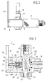
- the reference numeral 10 designates the filling station for an industrial gas such as nitrogen, helium, oxygen, and the like
- the letter B designates a cylinder to be filled with said gas delivered by the station 10 at high pressure, typically 200 bar.
- the station 10 includes a valve cock 11 which is connected by means of a pipe 12 to a filling tank, not shown; a check valve 13 is placed along the pipe 12 upstream of the valve 11 and is suitable to prevent the backflow of any residues contained in the cylinder B.
- the reference numeral 14 generally designates the filling device according to the invention, which substantially comprises a straight portion 15 of filling hose and an elbow-like body 16 for coupling said filling hose to the cylinder B.
- the hose 15 is advantageously of the flexible, high-strength, metal type provided with corrugations that accommodate an external belt C made of metal wire or the like, according to the known arrangement described in the prior Italian Utility Model application no. TO92U000044 filed on February 17, 1992.
- the elbow-like body 16 includes a first hollow shank 17 and a second hollow shank 18 which are arranged at 90 o to each other.
- One end of the hose 15 is permanently coupled to the first shank 17 by means of a threaded connector 19, and the other end of said hose is also permanently coupled to the valve cock 11 by means of a respective connector 20.
- the second shank 18 has a threaded ring connector 21 which is actuated manually to couple the body 16 to the cylinder B.
- the first shank 17 for coupling the hose 15 to the body 16 is rotatably mounted in said body with the interposition of sealing rings 22 of the O-ring type.
- the shank 17 is provided with an abutment shoulder 170 and with a threaded end 171 that receives a retaining nut 23.
- An axial hole 172 is formed in the shank 17 and is connected, by means of radial openings 173, to an annular chamber 24 which is in turn connected to the axial hole 180 of the second shank 18 for coupling to the cylinder B.
- a manually-operated valve 26 is also connected to the annular chamber of the body 16 and is meant to vent the filling hose 15 after the cylinder B has been filled, in order to facilitate the subsequent separation of the manual ring connector 21 of said cylinder.
- the valve 26 comprises a valve body 27 which slidingly contains a shutter 28 provided with a head 28a which is advantageously shaped like a truncated cone and is pushed by a spring 29 and by the pressure of the gas so that it hermetically engages by contact a corresponding frustum-shaped valve seat provided in a preferably nonmetallic bottom 30 of the valve body 27.
- the shutter 28 is elongated by means of a pin 31 which has a prism-like, typically triangular, cross-section and is slideable in a guiding and retention hole 32 of the body 16, in which it forms axial passages 33 for venting the gas from the annular chamber 24.
- the pin 31 protrudes from the body 16 enough to be engaged by a control lever 34 which is pivoted to the body 16 at the pivoting point 35 and is suitable, when rotated in the direction of the arrow F in contrast with the action of its own contrast spring 36, to move said pin axially and consequently open the shutter 28.
Landscapes
- Engineering & Computer Science (AREA)
- General Engineering & Computer Science (AREA)
- Mechanical Engineering (AREA)
- Filling Or Discharging Of Gas Storage Vessels (AREA)
Applications Claiming Priority (2)
| Application Number | Priority Date | Filing Date | Title |
|---|---|---|---|
| ITTO930266 IT231536Y1 (it) | 1993-12-14 | 1993-12-14 | Dispositivo di caricamento di bombole con gas tecnici ad alta pressione con valvola di scarico rapido. |
| ITTO930266 | 1993-12-14 |
Publications (1)
| Publication Number | Publication Date |
|---|---|
| EP0658719A1 true EP0658719A1 (en) | 1995-06-21 |
Family
ID=11411410
Family Applications (1)
| Application Number | Title | Priority Date | Filing Date |
|---|---|---|---|
| EP94119599A Withdrawn EP0658719A1 (en) | 1993-12-14 | 1994-12-12 | Device with quick venting valve for filling cylinders with industrial gases at high pressure |
Country Status (2)
| Country | Link |
|---|---|
| EP (1) | EP0658719A1 (it) |
| IT (1) | IT231536Y1 (it) |
Cited By (2)
| Publication number | Priority date | Publication date | Assignee | Title |
|---|---|---|---|---|
| DE10146457B4 (de) * | 2001-09-20 | 2006-11-30 | Messer Cutting & Welding Gmbh | Gasflaschen-Einheit |
| EP2821687A1 (en) * | 2013-07-04 | 2015-01-07 | Air Liquide Deutschland GmbH | Device and method for filling gases into high-pressure gas cylinders having different filling terminals |
Citations (4)
| Publication number | Priority date | Publication date | Assignee | Title |
|---|---|---|---|---|
| GB760640A (en) * | 1954-06-25 | 1956-11-07 | Plessey Co Ltd | Improvements in or relating to flexible hose or pipes |
| JPS5737197A (en) * | 1980-08-18 | 1982-03-01 | Nippon Sanso Kk | Gas filler |
| EP0400897A1 (en) * | 1989-06-02 | 1990-12-05 | Ronald Glossop | High pressure gas charging apparatus |
| DE9001650U1 (de) * | 1990-02-13 | 1991-06-06 | Robert von Keitz KG, 6250 Limburg | Ventil für die Entnahme von fließfähigen Proben aus Rohrleitungen oder Behältern |
-
1993
- 1993-12-14 IT ITTO930266 patent/IT231536Y1/it active IP Right Grant
-
1994
- 1994-12-12 EP EP94119599A patent/EP0658719A1/en not_active Withdrawn
Patent Citations (4)
| Publication number | Priority date | Publication date | Assignee | Title |
|---|---|---|---|---|
| GB760640A (en) * | 1954-06-25 | 1956-11-07 | Plessey Co Ltd | Improvements in or relating to flexible hose or pipes |
| JPS5737197A (en) * | 1980-08-18 | 1982-03-01 | Nippon Sanso Kk | Gas filler |
| EP0400897A1 (en) * | 1989-06-02 | 1990-12-05 | Ronald Glossop | High pressure gas charging apparatus |
| DE9001650U1 (de) * | 1990-02-13 | 1991-06-06 | Robert von Keitz KG, 6250 Limburg | Ventil für die Entnahme von fließfähigen Proben aus Rohrleitungen oder Behältern |
Non-Patent Citations (1)
| Title |
|---|
| PATENT ABSTRACTS OF JAPAN vol. 6, no. 105 (M - 136)<983> 15 June 1982 (1982-06-15) * |
Cited By (2)
| Publication number | Priority date | Publication date | Assignee | Title |
|---|---|---|---|---|
| DE10146457B4 (de) * | 2001-09-20 | 2006-11-30 | Messer Cutting & Welding Gmbh | Gasflaschen-Einheit |
| EP2821687A1 (en) * | 2013-07-04 | 2015-01-07 | Air Liquide Deutschland GmbH | Device and method for filling gases into high-pressure gas cylinders having different filling terminals |
Also Published As
| Publication number | Publication date |
|---|---|
| ITTO930266U1 (it) | 1995-06-14 |
| ITTO930266V0 (it) | 1993-12-14 |
| IT231536Y1 (it) | 1999-08-03 |
Similar Documents
| Publication | Publication Date | Title |
|---|---|---|
| US5095947A (en) | Pressure-sealed plug coupling | |
| US1946138A (en) | Pneumatic stopper for gas-mains | |
| US6640827B1 (en) | Hot tapping tool | |
| JPS6326470A (ja) | ガスタンクのための弁 | |
| US3760632A (en) | Pressure testing machines for tubes | |
| AU551786B2 (en) | Test head | |
| US6390158B2 (en) | Post valve yoke | |
| US4802504A (en) | Tap with flow limiter for gas bottles | |
| US4096372A (en) | Purge unit | |
| US5106061A (en) | Compact lance | |
| US4497332A (en) | Apparatus for servicing gas lines | |
| US5131636A (en) | Lance holder for a compact lance | |
| JPS6267391A (ja) | 管壁のポートを密封するための真空密封方法及び装置 | |
| US5996654A (en) | Quick-connect filling device for transferring fluids to a valve | |
| EP0651187A1 (en) | Sealing device for tubes and/or circular tanks | |
| EP1363052B1 (en) | Fast-flow discharge valve for a high-pressure inert gas fire extinguisher system | |
| EP0398849A2 (en) | A rapid-coupling valve for transferring and bottling compressed gases for technical uses | |
| EP3655683A1 (en) | Safety valve | |
| US3771762A (en) | Safely disconnectable flow limiter valves for a high pressure fluid line | |
| US3136344A (en) | Coupling device | |
| US3261382A (en) | Tank filling valve | |
| US3774480A (en) | Apparatus for rotating valves on gas cylinders | |
| US5791364A (en) | Attachment for stopper for plastic gas pipelines | |
| US4662654A (en) | Automated cylinder connector | |
| US6863087B1 (en) | Filling connection for a gas bottle valve |
Legal Events
| Date | Code | Title | Description |
|---|---|---|---|
| PUAI | Public reference made under article 153(3) epc to a published international application that has entered the european phase |
Free format text: ORIGINAL CODE: 0009012 |
|
| AK | Designated contracting states |
Kind code of ref document: A1 Designated state(s): DE ES FR GB |
|
| 17P | Request for examination filed |
Effective date: 19951129 |
|
| 17Q | First examination report despatched |
Effective date: 19970122 |
|
| STAA | Information on the status of an ep patent application or granted ep patent |
Free format text: STATUS: THE APPLICATION HAS BEEN WITHDRAWN |
|
| 18W | Application withdrawn |
Withdrawal date: 19970613 |