EP0658721A1 - Dispositif d'éclairage - Google Patents
Dispositif d'éclairage Download PDFInfo
- Publication number
- EP0658721A1 EP0658721A1 EP94119788A EP94119788A EP0658721A1 EP 0658721 A1 EP0658721 A1 EP 0658721A1 EP 94119788 A EP94119788 A EP 94119788A EP 94119788 A EP94119788 A EP 94119788A EP 0658721 A1 EP0658721 A1 EP 0658721A1
- Authority
- EP
- European Patent Office
- Prior art keywords
- lighting device
- light
- light source
- reflection surface
- reflector
- Prior art date
- Legal status (The legal status is an assumption and is not a legal conclusion. Google has not performed a legal analysis and makes no representation as to the accuracy of the status listed.)
- Granted
Links
- 238000003908 quality control method Methods 0.000 claims description 6
- 230000000007 visual effect Effects 0.000 claims description 4
- 238000005286 illumination Methods 0.000 claims 1
- 238000009434 installation Methods 0.000 description 6
- 238000004519 manufacturing process Methods 0.000 description 6
- 230000003278 mimic effect Effects 0.000 description 3
- 238000012544 monitoring process Methods 0.000 description 3
- 230000008921 facial expression Effects 0.000 description 2
- 238000000034 method Methods 0.000 description 2
- 230000005855 radiation Effects 0.000 description 2
- 230000002411 adverse Effects 0.000 description 1
- 238000009776 industrial production Methods 0.000 description 1
- 239000000203 mixture Substances 0.000 description 1
- 230000010287 polarization Effects 0.000 description 1
Images



Classifications
-
- F—MECHANICAL ENGINEERING; LIGHTING; HEATING; WEAPONS; BLASTING
- F21—LIGHTING
- F21V—FUNCTIONAL FEATURES OR DETAILS OF LIGHTING DEVICES OR SYSTEMS THEREOF; STRUCTURAL COMBINATIONS OF LIGHTING DEVICES WITH OTHER ARTICLES, NOT OTHERWISE PROVIDED FOR
- F21V7/00—Reflectors for light sources
- F21V7/10—Construction
- F21V7/16—Construction with provision for adjusting the curvature
-
- F—MECHANICAL ENGINEERING; LIGHTING; HEATING; WEAPONS; BLASTING
- F21—LIGHTING
- F21V—FUNCTIONAL FEATURES OR DETAILS OF LIGHTING DEVICES OR SYSTEMS THEREOF; STRUCTURAL COMBINATIONS OF LIGHTING DEVICES WITH OTHER ARTICLES, NOT OTHERWISE PROVIDED FOR
- F21V14/00—Controlling the distribution of the light emitted by adjustment of elements
- F21V14/04—Controlling the distribution of the light emitted by adjustment of elements by movement of reflectors
-
- F—MECHANICAL ENGINEERING; LIGHTING; HEATING; WEAPONS; BLASTING
- F21—LIGHTING
- F21V—FUNCTIONAL FEATURES OR DETAILS OF LIGHTING DEVICES OR SYSTEMS THEREOF; STRUCTURAL COMBINATIONS OF LIGHTING DEVICES WITH OTHER ARTICLES, NOT OTHERWISE PROVIDED FOR
- F21V7/00—Reflectors for light sources
- F21V7/0008—Reflectors for light sources providing for indirect lighting
-
- F—MECHANICAL ENGINEERING; LIGHTING; HEATING; WEAPONS; BLASTING
- F21—LIGHTING
- F21V—FUNCTIONAL FEATURES OR DETAILS OF LIGHTING DEVICES OR SYSTEMS THEREOF; STRUCTURAL COMBINATIONS OF LIGHTING DEVICES WITH OTHER ARTICLES, NOT OTHERWISE PROVIDED FOR
- F21V7/00—Reflectors for light sources
- F21V7/10—Construction
- F21V7/18—Construction with provision for folding or collapsing
-
- G—PHYSICS
- G01—MEASURING; TESTING
- G01N—INVESTIGATING OR ANALYSING MATERIALS BY DETERMINING THEIR CHEMICAL OR PHYSICAL PROPERTIES
- G01N21/00—Investigating or analysing materials by the use of optical means, i.e. using sub-millimetre waves, infrared, visible or ultraviolet light
- G01N21/84—Systems specially adapted for particular applications
- G01N21/88—Investigating the presence of flaws or contamination
- G01N21/8806—Specially adapted optical and illumination features
-
- F—MECHANICAL ENGINEERING; LIGHTING; HEATING; WEAPONS; BLASTING
- F21—LIGHTING
- F21V—FUNCTIONAL FEATURES OR DETAILS OF LIGHTING DEVICES OR SYSTEMS THEREOF; STRUCTURAL COMBINATIONS OF LIGHTING DEVICES WITH OTHER ARTICLES, NOT OTHERWISE PROVIDED FOR
- F21V11/00—Screens not covered by groups F21V1/00, F21V3/00, F21V7/00 or F21V9/00
- F21V11/16—Screens not covered by groups F21V1/00, F21V3/00, F21V7/00 or F21V9/00 using sheets without apertures, e.g. fixed
- F21V11/18—Screens not covered by groups F21V1/00, F21V3/00, F21V7/00 or F21V9/00 using sheets without apertures, e.g. fixed movable, e.g. flaps, slides
Definitions
- the invention relates to a lighting device, in particular for use in quality control processes, with at least one light source, at least one deflection reflector and at least one reflection surface.
- the light source, the deflecting reflectors and the reflecting surface must be optimally aligned with one another and the deflecting reflectors and in particular the reflecting surface must be set exactly.
- Such installations are very complex and are arranged in the area of the production lines as a fixed installation.
- a disadvantage of this known device is that the installation of the components must be planned with great care. Already Small errors in the pre-installation of the holding devices, for example, can lead to unusable lighting conditions. Due to the fixed installation, the known lighting device is very complex and costly, both with regard to the parts used and with regard to the assembly. Finally, the previously known lighting device is susceptible to failure, since in particular the light source and the associated deflecting reflectors are arranged in the production or work area and can easily be adjusted accidentally. Because of the distance between the lighting device and the light sail, the lighting conditions can be adversely affected. However, since it is important for the desired visual quality controls that the beam path of the light is precisely defined, that is, the light mixture, parallelism and the like are clearly defined, such disturbances can affect the entire production.
- the object of the invention is to improve a lighting device of the generic type in such a way that it can be manufactured and / or installed with little economic outlay, can be easily set up, is variable with regard to the place of use and is generally not susceptible to faults.
- the generic lighting device is improved in that the at least one light source, the at least one deflection reflector and at least one reflection surface are connected to one another to form an assembly.
- the lighting device according to the invention makes it possible for the light source, the deflection reflector and the reflection surface to be aligned with one another in a basic setting, in order then to be arranged as a uniform assembly relative to the area to be monitored. This considerably simplifies the installation of the lighting device and thus makes the use of such devices more economical. Furthermore, all components of the device can be arranged in an area that is not susceptible to faults relative to the area to be monitored.
- the light source is advantageously a luminaire with a housing with a substantially rectangular front.
- the deflection reflector is on the light source housing arranged in the area of the front surface.
- the deflection reflector can then have the shape desired for the intended use, so that the desired lighting can be achieved.
- the reflection surface is arranged within the deflection reflector, the entire lighting device has a one-piece character, the luminaire housing being enlarged by the deflection reflector and the required reflection surfaces being arranged in the deflection reflector.
- the light source can expediently be provided with at least one filter which is arranged in the beam path. The quality, the radiation area and possibly also the polarization of the light can be specified by the corresponding filters.
- the reflector surface is advantageously a light sail, which advantageously consists of individual reflector lamellae. In this way, the entire light sail can advantageously be adjustable, or, additionally or alternatively, individual reflector slats can also be adjusted.
- an adjustable cover flap is arranged in the deflection reflector opposite the light sail. This allows the radiation path of the light to be limited and adjusted.
- the unit light source, deflecting reflector and reflecting surface are arranged on a supporting frame.
- a supporting structure can be provided with fastening devices in order to ensure simple fastening in the surveillance area.
- the switch cabinet required for the lighting operation is arranged on the support frame, in which a dimmer device is advantageously accommodated.
- the number of light sources, the deflecting reflectors and the reflecting surfaces depend on the desired range of applications. Due to the integrated design, the lighting device according to the invention can be used with a few Components can be manufactured and set up inexpensively. In addition, the use of the device is highly variable and only slightly susceptible to faults.
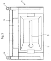
- the lighting device 1 comprises a lamp 2, a deflection reflector 3 and a reflection surface 4.
- the deflection reflector 3 is attached to the connection area 5 on the lamp 2.
- the reflection surface 4 is in turn attached to the deflection reflector 3 and adjustable via an adjustment mimic 6.
- the reflection surface 4 consists of individual reflection slats 7, which in turn are adjustable relative to one another.
- a dimming flap 8 is arranged on the deflection reflector, which can be rotatably supported on one side via an adjustment mimic 9 relative to the beam path.
- the assembly consisting of lamp 2, deflecting reflector 3, reflecting surface 4 and anti-glare flap 8 is arranged on a supporting frame 10. It is a lightweight support frame to which the assembly is attached using retaining straps. Eyebolts 11 for fastening the lighting device 1 in the monitoring area are arranged on the support frame 10.
- An attachment profile 12 is attached to the support frame 10, to which the control cabinet 13 is fastened with an operating panel 14. The overall unit thus created is regarding of the place of use highly variable and economical to manufacture and set up with regard to the individual elements.
- the external dimensions of such a device are, for example, 1.4 meters x 0.7 meters x 0.5 meters.
- the device can, for example, be suspended from a ceiling by means of chains, for which purpose quick connection elements such as snap hooks or the like can be used.
- Simple control elements for example plastic balls, which are easy to operate from the outside, are arranged on the adjustment mimic, as can be seen in FIG.
- a lamp 15 is inserted into the lamp 2, which can be, for example, a 250 to 400 watt lamp.
- the lighting area can be optimally adjusted with the lighting device 1 according to the invention.
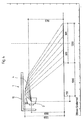
- the reflection surface 4 is set in its position on the lamp such that an approximately 1.2 meter long illuminated monitoring area is formed after about one meter from the beam exit from the lamp housing. By lowering the reflection surface, this monitoring area can be moved to a different distance from the lighting device according to FIG.
- the dimensions given in FIGS. 4 and 5 are chosen only as examples to explain the exemplary embodiment.
Landscapes
- Engineering & Computer Science (AREA)
- General Engineering & Computer Science (AREA)
- Physics & Mathematics (AREA)
- Health & Medical Sciences (AREA)
- Life Sciences & Earth Sciences (AREA)
- Chemical & Material Sciences (AREA)
- Analytical Chemistry (AREA)
- Biochemistry (AREA)
- General Health & Medical Sciences (AREA)
- General Physics & Mathematics (AREA)
- Immunology (AREA)
- Pathology (AREA)
- Non-Portable Lighting Devices Or Systems Thereof (AREA)
- Securing Globes, Refractors, Reflectors Or The Like (AREA)
- Vehicle Body Suspensions (AREA)
- Polarising Elements (AREA)
- Seal Device For Vehicle (AREA)
Applications Claiming Priority (2)
| Application Number | Priority Date | Filing Date | Title |
|---|---|---|---|
| DE9319537U DE9319537U1 (de) | 1993-12-18 | 1993-12-18 | Beleuchtungsvorrichtung |
| DE9319537U | 1993-12-18 |
Publications (2)
| Publication Number | Publication Date |
|---|---|
| EP0658721A1 true EP0658721A1 (fr) | 1995-06-21 |
| EP0658721B1 EP0658721B1 (fr) | 1997-09-24 |
Family
ID=6902236
Family Applications (1)
| Application Number | Title | Priority Date | Filing Date |
|---|---|---|---|
| EP94119788A Expired - Lifetime EP0658721B1 (fr) | 1993-12-18 | 1994-12-15 | Dispositif d'éclairage |
Country Status (2)
| Country | Link |
|---|---|
| EP (1) | EP0658721B1 (fr) |
| DE (2) | DE9319537U1 (fr) |
Cited By (5)
| Publication number | Priority date | Publication date | Assignee | Title |
|---|---|---|---|---|
| WO1997037329A1 (fr) * | 1996-04-02 | 1997-10-09 | Koenig & Bauer-Albert Ag | Procede et dispositif pour evaluer la qualite d'un materiau traite |
| EP0947827A1 (fr) * | 1998-04-03 | 1999-10-06 | VH Lichttechnische Spezialgeräte GmbH | Dispositif pour l'inspection visuelle de surfaces de corps situées dans des plans différents |
| EP0900976A3 (fr) * | 1997-09-02 | 2000-05-17 | L D Industries Ltd | Zone d' inspection et luminaire pour cette zone |
| EP1103756A3 (fr) * | 1999-11-26 | 2004-02-18 | Spectral Gesellschaft für Lichttechnik mit beschränkter Haftung | Luminaire |
| CN112666177A (zh) * | 2019-10-15 | 2021-04-16 | 全耐塑料欧洲公司 | 用于评估涂层质量的装置和方法 |
Families Citing this family (4)
| Publication number | Priority date | Publication date | Assignee | Title |
|---|---|---|---|---|
| DE10103781A1 (de) * | 2001-01-29 | 2002-08-22 | Zimmermann Gmbh Co Kg Rudolf | Einrichtung zur Beleuchtung von Rettungswegen |
| DE20307076U1 (de) | 2003-05-06 | 2003-08-28 | VH Lichttechnische Spezialgeräte GmbH, 53604 Bad Honnef | Beleuchtungsvorrichtung |
| DE102010047539B4 (de) | 2009-10-07 | 2016-07-28 | Wenker Gmbh & Co. Kg | Inspektionstunnel |
| WO2025181594A1 (fr) * | 2024-02-28 | 2025-09-04 | Imax Corporation | Protection pour fenêtre gauche de cabine de projection dans un théâtre |
Citations (10)
| Publication number | Priority date | Publication date | Assignee | Title |
|---|---|---|---|---|
| US1782629A (en) * | 1929-01-29 | 1930-11-25 | Floyd N Pape | Shield for motor-vehicle headlights |
| AT202652B (de) * | 1957-02-18 | 1959-03-25 | Licentia Gmbh | Breitstrahlende Leuchte |
| US3686495A (en) * | 1969-04-24 | 1972-08-22 | Crouse Hinds Co | Tensioner reflector sheet with press forms |
| DE2523643A1 (de) * | 1975-05-28 | 1976-12-02 | Schurig Hans Joachim | Reflektor |
| US4007365A (en) * | 1974-04-10 | 1977-02-08 | Siemens Aktiengesellschaft | Lighting fixture with tiltable reflector elements |
| GB1482743A (en) * | 1974-09-18 | 1977-08-10 | Wallace Knight Ltd | Lamp housing |
| GB2113864A (en) * | 1982-01-26 | 1983-08-10 | Slidex Corp | Desktop film viewer |
| AT379006B (de) * | 1981-01-09 | 1985-11-11 | Austria Email Eht Ag | Breitstrahlende leuchte mit einer im wesentlichen stabfoermigen lampe |
| US4872098A (en) * | 1989-03-20 | 1989-10-03 | Lpi Limited Partnership | Variable beam floodlight |
| FR2653530A1 (fr) * | 1989-10-19 | 1991-04-26 | Emc2 | Dispositif d'eclairage electrique direct ou indirect, notamment lampe murale ou lampadaire. |
Family Cites Families (10)
| Publication number | Priority date | Publication date | Assignee | Title |
|---|---|---|---|---|
| DE2533873C3 (de) * | 1975-07-29 | 1979-01-25 | Erwin Sick Gmbh Optik-Elektronik, 7808 Waldkirch | Vorrichtung zum Erkennen von Flaschenfarben |
| IT1106658B (it) * | 1978-05-24 | 1985-11-18 | Eurodent Di Conti Giacomo E C | Lampada a flusso luminoso regolabile |
| DE7931248U1 (de) * | 1979-11-06 | 1980-01-31 | Ernst Rademacher Gmbh, 4005 Meerbusch | Gehaeuse fuer eine leuchte |
| DE8316218U1 (de) * | 1983-06-03 | 1984-08-09 | Licentia Patent-Verwaltungs-Gmbh, 6000 Frankfurt | Innenraumleuchte fuer eine hochdrucklampe |
| DE8528706U1 (de) * | 1985-10-09 | 1986-11-06 | Licentia Patent-Verwaltungs-Gmbh, 6000 Frankfurt | Langgestreckte Leuchte |
| GB2187902A (en) * | 1986-03-13 | 1987-09-16 | Lutron Electronics Co | Lighting control system |
| DE8715104U1 (de) * | 1987-11-13 | 1988-04-14 | S.L.E. GmbH, 7850 Lörrach | Beleuchtungsvorrichtung |
| DE3822303A1 (de) * | 1987-12-10 | 1989-06-22 | Birkle Gebhard | Vorrichtung zum optischen abtasten der oberflaeche eines objektes, dessen oberflaeche licht zu reflektieren oder streuen imstande ist und verfahren hierzu |
| DE69311583T2 (de) * | 1992-03-16 | 1998-01-08 | Philips Electronics Nv | Leuchte |
| DE9204375U1 (de) * | 1992-03-31 | 1992-06-04 | Spectral Gesellschaft Fuer Lichttechnik Mbh, 7800 Freiburg | Leuchte |
-
1993
- 1993-12-18 DE DE9319537U patent/DE9319537U1/de not_active Expired - Lifetime
-
1994
- 1994-12-15 EP EP94119788A patent/EP0658721B1/fr not_active Expired - Lifetime
- 1994-12-15 DE DE59404160T patent/DE59404160D1/de not_active Expired - Fee Related
Patent Citations (10)
| Publication number | Priority date | Publication date | Assignee | Title |
|---|---|---|---|---|
| US1782629A (en) * | 1929-01-29 | 1930-11-25 | Floyd N Pape | Shield for motor-vehicle headlights |
| AT202652B (de) * | 1957-02-18 | 1959-03-25 | Licentia Gmbh | Breitstrahlende Leuchte |
| US3686495A (en) * | 1969-04-24 | 1972-08-22 | Crouse Hinds Co | Tensioner reflector sheet with press forms |
| US4007365A (en) * | 1974-04-10 | 1977-02-08 | Siemens Aktiengesellschaft | Lighting fixture with tiltable reflector elements |
| GB1482743A (en) * | 1974-09-18 | 1977-08-10 | Wallace Knight Ltd | Lamp housing |
| DE2523643A1 (de) * | 1975-05-28 | 1976-12-02 | Schurig Hans Joachim | Reflektor |
| AT379006B (de) * | 1981-01-09 | 1985-11-11 | Austria Email Eht Ag | Breitstrahlende leuchte mit einer im wesentlichen stabfoermigen lampe |
| GB2113864A (en) * | 1982-01-26 | 1983-08-10 | Slidex Corp | Desktop film viewer |
| US4872098A (en) * | 1989-03-20 | 1989-10-03 | Lpi Limited Partnership | Variable beam floodlight |
| FR2653530A1 (fr) * | 1989-10-19 | 1991-04-26 | Emc2 | Dispositif d'eclairage electrique direct ou indirect, notamment lampe murale ou lampadaire. |
Cited By (7)
| Publication number | Priority date | Publication date | Assignee | Title |
|---|---|---|---|---|
| WO1997037329A1 (fr) * | 1996-04-02 | 1997-10-09 | Koenig & Bauer-Albert Ag | Procede et dispositif pour evaluer la qualite d'un materiau traite |
| US6111261A (en) * | 1996-04-02 | 2000-08-29 | Koenig & Bauer Aktiengesellschaft | Process and device for assessing the quality of processed material |
| EP0900976A3 (fr) * | 1997-09-02 | 2000-05-17 | L D Industries Ltd | Zone d' inspection et luminaire pour cette zone |
| EP0947827A1 (fr) * | 1998-04-03 | 1999-10-06 | VH Lichttechnische Spezialgeräte GmbH | Dispositif pour l'inspection visuelle de surfaces de corps situées dans des plans différents |
| EP1103756A3 (fr) * | 1999-11-26 | 2004-02-18 | Spectral Gesellschaft für Lichttechnik mit beschränkter Haftung | Luminaire |
| CN112666177A (zh) * | 2019-10-15 | 2021-04-16 | 全耐塑料欧洲公司 | 用于评估涂层质量的装置和方法 |
| EP3809119A1 (fr) * | 2019-10-15 | 2021-04-21 | Compagnie Plastic Omnium SE | Dispositif et procédé pour l'évaluation de la qualité d'un revêtement |
Also Published As
| Publication number | Publication date |
|---|---|
| EP0658721B1 (fr) | 1997-09-24 |
| DE59404160D1 (de) | 1997-10-30 |
| DE9319537U1 (de) | 1994-09-22 |
Similar Documents
| Publication | Publication Date | Title |
|---|---|---|
| EP1649212B1 (fr) | Dispositif d'eclairage de locaux | |
| DE69207633T2 (de) | Leuchtanzeigevorrichtung | |
| EP0898686B2 (fr) | Systeme d'eclairage muni d'un corps de base servant de support pour au moins une lampe | |
| EP1255950A1 (fr) | Appareil d'eclairage | |
| DE102009011794B4 (de) | Beleuchtungsanordnung mit Tragprofil | |
| EP0658721B1 (fr) | Dispositif d'éclairage | |
| EP0819232B1 (fr) | Adaptateur pour reflecteurs miniatures a faisceau libre | |
| DE3316000A1 (de) | Leuchte fuer eine langgestreckte lichtquelle | |
| DE29501661U1 (de) | Leuchte mit mindestens einem Leuchtmittel | |
| EP0952390A2 (fr) | Chemin lumineux | |
| CH712778A2 (de) | Anordnung zur Lichtabgabe. | |
| DE3836611A1 (de) | Decken-einbauleuchte fuer eine paneeldecke | |
| DE102023121516A1 (de) | Beleuchtungsvorrichtung | |
| EP0008004A1 (fr) | Appareil d'éclairage à réflecteur amovible | |
| DE19721340A1 (de) | Leuchte | |
| EP3832194B1 (fr) | Système optique permettant d'influencer l'émission lumineuse d'une source lumineuse allongée | |
| EP0833101B1 (fr) | Ensemble réflecteur | |
| DE8711032U1 (de) | Einbauleuchte für Kompakt-Leuchtstoffröhren | |
| EP3276251A1 (fr) | Éclairage ayant une forme extérieure modifiable | |
| EP1205744B1 (fr) | Appareil pour l'inspection des matériaux avec lumière réflechie approprié pour des caméras | |
| EP2924349A1 (fr) | Éclairage entièrement plat | |
| EP1258675B1 (fr) | Dispositif d'éclairage avec cône lumineux réglable | |
| DE3715559A1 (de) | Fluessigkristallanzeige | |
| DE3239783A1 (de) | Beleuchtungseinrichtung | |
| DE202007013177U1 (de) | Leuchte |
Legal Events
| Date | Code | Title | Description |
|---|---|---|---|
| PUAI | Public reference made under article 153(3) epc to a published international application that has entered the european phase |
Free format text: ORIGINAL CODE: 0009012 |
|
| AK | Designated contracting states |
Kind code of ref document: A1 Designated state(s): BE DE FR GB |
|
| 17P | Request for examination filed |
Effective date: 19950913 |
|
| 17Q | First examination report despatched |
Effective date: 19960712 |
|
| GRAG | Despatch of communication of intention to grant |
Free format text: ORIGINAL CODE: EPIDOS AGRA |
|
| GRAH | Despatch of communication of intention to grant a patent |
Free format text: ORIGINAL CODE: EPIDOS IGRA |
|
| GRAH | Despatch of communication of intention to grant a patent |
Free format text: ORIGINAL CODE: EPIDOS IGRA |
|
| GRAA | (expected) grant |
Free format text: ORIGINAL CODE: 0009210 |
|
| AK | Designated contracting states |
Kind code of ref document: B1 Designated state(s): BE DE FR GB |
|
| REF | Corresponds to: |
Ref document number: 59404160 Country of ref document: DE Date of ref document: 19971030 |
|
| GBT | Gb: translation of ep patent filed (gb section 77(6)(a)/1977) |
Effective date: 19971113 |
|
| ET | Fr: translation filed | ||
| PLBE | No opposition filed within time limit |
Free format text: ORIGINAL CODE: 0009261 |
|
| STAA | Information on the status of an ep patent application or granted ep patent |
Free format text: STATUS: NO OPPOSITION FILED WITHIN TIME LIMIT |
|
| 26N | No opposition filed | ||
| REG | Reference to a national code |
Ref country code: GB Ref legal event code: IF02 |
|
| PGFP | Annual fee paid to national office [announced via postgrant information from national office to epo] |
Ref country code: FR Payment date: 20051219 Year of fee payment: 12 |
|
| PGFP | Annual fee paid to national office [announced via postgrant information from national office to epo] |
Ref country code: GB Payment date: 20051222 Year of fee payment: 12 |
|
| PGFP | Annual fee paid to national office [announced via postgrant information from national office to epo] |
Ref country code: BE Payment date: 20060116 Year of fee payment: 12 |
|
| PGFP | Annual fee paid to national office [announced via postgrant information from national office to epo] |
Ref country code: DE Payment date: 20061214 Year of fee payment: 13 |
|
| PG25 | Lapsed in a contracting state [announced via postgrant information from national office to epo] |
Ref country code: BE Free format text: LAPSE BECAUSE OF NON-PAYMENT OF DUE FEES Effective date: 20061231 |
|
| GBPC | Gb: european patent ceased through non-payment of renewal fee |
Effective date: 20061215 |
|
| REG | Reference to a national code |
Ref country code: FR Ref legal event code: ST Effective date: 20070831 |
|
| PG25 | Lapsed in a contracting state [announced via postgrant information from national office to epo] |
Ref country code: GB Free format text: LAPSE BECAUSE OF NON-PAYMENT OF DUE FEES Effective date: 20061215 |
|
| BERE | Be: lapsed |
Owner name: *VH LICHTTECHNISCHE SPEZIALGERATE G.M.B.H. Effective date: 20061231 |
|
| PG25 | Lapsed in a contracting state [announced via postgrant information from national office to epo] |
Ref country code: FR Free format text: LAPSE BECAUSE OF NON-PAYMENT OF DUE FEES Effective date: 20070102 |
|
| PG25 | Lapsed in a contracting state [announced via postgrant information from national office to epo] |
Ref country code: DE Free format text: LAPSE BECAUSE OF NON-PAYMENT OF DUE FEES Effective date: 20080701 |