EP0658755B1 - Procédé pour évaluer les signaux de sortie de deux capteurs de pression, dispositif avec deux capteurs et tête de mesure de pression - Google Patents
Procédé pour évaluer les signaux de sortie de deux capteurs de pression, dispositif avec deux capteurs et tête de mesure de pression Download PDFInfo
- Publication number
- EP0658755B1 EP0658755B1 EP94118628A EP94118628A EP0658755B1 EP 0658755 B1 EP0658755 B1 EP 0658755B1 EP 94118628 A EP94118628 A EP 94118628A EP 94118628 A EP94118628 A EP 94118628A EP 0658755 B1 EP0658755 B1 EP 0658755B1
- Authority
- EP
- European Patent Office
- Prior art keywords
- sensor
- output signal
- pressure
- weighting
- sensors
- Prior art date
- Legal status (The legal status is an assumption and is not a legal conclusion. Google has not performed a legal analysis and makes no representation as to the accuracy of the status listed.)
- Expired - Lifetime
Links
- 238000000034 method Methods 0.000 title claims description 26
- 238000005259 measurement Methods 0.000 claims description 24
- 238000009530 blood pressure measurement Methods 0.000 claims description 14
- 238000011156 evaluation Methods 0.000 claims description 11
- 238000012545 processing Methods 0.000 claims description 6
- 230000001419 dependent effect Effects 0.000 claims description 4
- 239000012528 membrane Substances 0.000 claims description 4
- 238000013213 extrapolation Methods 0.000 claims 1
- 239000007789 gas Substances 0.000 description 10
- 238000010438 heat treatment Methods 0.000 description 8
- 239000000243 solution Substances 0.000 description 6
- 230000007704 transition Effects 0.000 description 6
- 239000010453 quartz Substances 0.000 description 5
- VYPSYNLAJGMNEJ-UHFFFAOYSA-N silicon dioxide Inorganic materials O=[Si]=O VYPSYNLAJGMNEJ-UHFFFAOYSA-N 0.000 description 5
- 230000001276 controlling effect Effects 0.000 description 4
- 230000000694 effects Effects 0.000 description 3
- 239000000654 additive Substances 0.000 description 2
- 230000000996 additive effect Effects 0.000 description 2
- 230000015572 biosynthetic process Effects 0.000 description 2
- 235000008733 Citrus aurantifolia Nutrition 0.000 description 1
- 240000006909 Tilia x europaea Species 0.000 description 1
- 235000011941 Tilia x europaea Nutrition 0.000 description 1
- 230000006978 adaptation Effects 0.000 description 1
- 230000032683 aging Effects 0.000 description 1
- 238000013459 approach Methods 0.000 description 1
- 230000000295 complement effect Effects 0.000 description 1
- 230000007423 decrease Effects 0.000 description 1
- 238000013461 design Methods 0.000 description 1
- 238000011161 development Methods 0.000 description 1
- 230000018109 developmental process Effects 0.000 description 1
- 238000010586 diagram Methods 0.000 description 1
- 238000009434 installation Methods 0.000 description 1
- 239000004571 lime Substances 0.000 description 1
- 230000001105 regulatory effect Effects 0.000 description 1
- 239000004065 semiconductor Substances 0.000 description 1
- 230000035945 sensitivity Effects 0.000 description 1
- 229910000859 α-Fe Inorganic materials 0.000 description 1
Images




Classifications
-
- G—PHYSICS
- G01—MEASURING; TESTING
- G01L—MEASURING FORCE, STRESS, TORQUE, WORK, MECHANICAL POWER, MECHANICAL EFFICIENCY, OR FLUID PRESSURE
- G01L21/00—Vacuum gauges
- G01L21/30—Vacuum gauges by making use of ionisation effects
- G01L21/34—Vacuum gauges by making use of ionisation effects using electric discharge tubes with cold cathodes
-
- G—PHYSICS
- G01—MEASURING; TESTING
- G01L—MEASURING FORCE, STRESS, TORQUE, WORK, MECHANICAL POWER, MECHANICAL EFFICIENCY, OR FLUID PRESSURE
- G01L21/00—Vacuum gauges
- G01L21/10—Vacuum gauges by measuring variations in the heat conductivity of the medium, the pressure of which is to be measured
- G01L21/12—Vacuum gauges by measuring variations in the heat conductivity of the medium, the pressure of which is to be measured measuring changes in electric resistance of measuring members, e.g. of filaments; Vacuum gauges of the Pirani type
Definitions
- the present invention relates to a method for evaluation the output signals of two pressure sensors according to the generic term of claim 1 and a pressure measuring arrangement according to the preamble of claim 6 and a pressure measuring head according to the preamble of claim 14.
- the present invention is based on the above the technique known from EP-A-0 347 144.
- a quartz oscillator is exposed to the vacuum and similar a Pirani sensor that conducts heat from a heating coil the environment due to the heating effect on the quartz oscillator detected.
- the heating current of the filament is regulated so that with varying pressure the resonance frequency of the Quartz oscillator remains constant.
- the heating coil is fed as a control actuator electrical heating energy measured.
- As a second sensor output signal becomes the resonance voltage of the quartz oscillator measured.
- the object of the present invention is a method to create the type mentioned, in which, depending on known pressure range to be covered Pressure measuring sensors combined with their specific measuring ranges can be made without the area transition, i.e. in the Intermediate range, measurement signal jumps or hysteresis effects arise.
- a particularly preferred sensor combination is that a Pirani sensor and a cold cathode ionization sensor.
- the preferred one mentioned combination compared to the use of Pirani sensors with hot cathode ionization sensors the essential Advantage on that the cold cathode ionization sensor has much less heat development than a hot cathode ionization sensor. Thermal interference from one sensor on the other and there are disruptions from exhaust gases greatly reduced. This allows the combination to be built a Pirani sensor and a cold cathode ionization sensor design much denser than the structural union a Pirani sensor and a hot cathode ionization sensor.
- the weighted signal overlay like mentioned, by analog technology or, as yet to be explained is, by pulse width modulation or possibly also through arithmetic processing of digitized sensor output signals take place, according to the wording of claim 4.
- the multiplicative weighting corresponding to the second, in Claim 1 specified variant, which also in the invention preferred sensor combination Pirani sensor / cold cathode ionization sensor is preferably used made according to the wording of claim 5.
- the weighting function becomes optimal kind by combining the Pirani output signal and of a feedback signal controlled, the latter mentioned Signal derived from the weighted combined output signal is.
- a pressure measuring sensor according to the invention is a solution the above mentioned task after the characteristic part of Claim 6 from, preferred embodiments according to the claims 7 to 13.
- a pressure measuring head according to the invention according to the wording of Claim 14 is constructed with a pressure measuring arrangement according to one of claims 6 to 13 and has, according to The wording of claim 15, the preferred combination mentioned above a Pirani sensor and a cold cathode ionization sensor on which, together with a measurement circuit for this, are structurally united on the head.
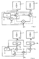
- sensors 1 and 3 of the type "p" and "k".
- the sensors 1 and 3 emit output signals p p and p k as a function of the same physical quantity p to be detected.
- Sensor 1 emits a representative measurement signal in an upper range of values of the physical quantity p, sensor 3 in the lower range of values of the physical quantity p.
- the output signals of sensors 1 and 3 are on the one hand fed to a weighting function unit 5, on the other hand a measurement value determination unit 7, the latter an output signal A as a representative of the physical quantity p Emits signal.
- An intermediate range ⁇ P is defined within which the transition from sensor 1 to sensor 2 with respect to representative measurement.
- the weighting functional unit is 5 also the output signal A of the measured value determination unit 7 fed, and it is on it, as a function of the sensor output signals as well as the output signal of the measurement value determination unit, the weighting function f is formed.
- the measured value determination unit 7 becomes the output signal A as a function the sensor output signals and the weighting function f educated.
- f is the weighting function and runs in the intermediate range ⁇ P between the values 0 and 1, for example such that, according to (1) and Fig. 1, the weighting function assumes the value 0 on the left edge of ⁇ P and the value 1 on the right.
- the measurement value determination unit is also shown in broken lines here 7 entered.
- pressure sensors used are not additive Error, i.e. Zero error, priority, but multiplicative Effects, i.e. Curve slope error.
- the present invention primarily based pressure measurement problem selected the second type of weighting, namely the multiplicative Combination of the pressure sensor output signals according to FIGS. 3 and (2).
- the output signal of the Pirani sensor 1 is therefore conducted via a logarithmization unit 9 p
- the output signal of the cold cathode ionization sensor 3, p k is conducted via a logarithmization unit 9 k .
- Both units 9 are based, for example, on the principle of utilizing the base emitter / collector current dependency mentioned.
- the signals U p and U k are weighted accordingly with the weighting functions f from the output of the weighting function unit 5, or 1-f, and at the summation unit 13 to form the expression (4), for example in Art analog programming, summed.
- the upper measuring range limit of the cold cathode ionization sensor 3 is to be set at 10 -2 mbar, the lower measuring range limit of the Pirani sensor at 10 -4 mbar.
- the Pirani sensor at 10 -4 mbar.
- a and b denote freely selectable constants.
- This weighting function should meet the conditions in (5a) and (5b) are sufficient and in the intermediate area monotonously and continuously with the Pressure increase.
- the pulse width t or more generally the duty cycle is controlled with the output signal of the Pirani sensor or with U p (3).
- FIG. 7 shows a circuit configuration according to principle (e) which is preferred today.
- the output signal p p of the Pirani Pirani measuring bridge circuit 21 with Pirani sensor 1 is logarithmized at a logarithmic circuit 22, which gives U p .
- the adjustment of U p for p ⁇ ⁇ takes place on an adjustable current source 24 and the adjustment for p ⁇ 0 on a potentiometer circuit 25.
- the high-voltage power supply 27 of the cold cathode ionization measuring arrangement 28 with the cold cathode ionization sensor 3 is put into operation from pressure values below it.
- the output signal I k is logarithmized at a "logarithmic circuit" 29.
- the output signal U k and the output signal U p of the "logarithmic circuit" 22 are fed to the weighting and measurement value determination circuit 5, 7, which operates according to the principle explained with reference to FIG. 6, but in which, according to (f), the output signal U A controls the duty cycle t / T together with U p .
- the sensors with their measuring circuits, generate measuring characteristic-specific output characteristics V p , I k . How these characteristic curves are converted into logarithmically dependent signals U p , I k is explicitly described in CH-A-684 805 for the Pirani principle.
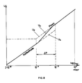
- FIG. 8 shows the measurement characteristic curve U A realized with the arrangement according to FIG. 7, dashed lines the sizes U p and U k , assuming that the curves for U p and U k differ, for example, because of the type of gas which differs from the calibration gas.
- a combination measuring head according to the invention shown schematically simplified, designed as a flange connection for a vacuum chamber.
- the measuring chamber 33 as a plasma space of the cold cathode ionization sensor arrangement 3 pressurized.
- the anode pin with measuring current connection and high voltage connection 35 and 37 the cathode wall.
- the necessary axial magnetic field by means of ferrite magnetic rings 38 generated.
- position symbol 39 denotes one on the anode pin 34 attached arrangement, which thanks to sharp edged Structure that promotes the ignition of the discharge.
- a Pirani measuring arrangement 43 with a heating coil 45 is provided.
- the high voltage supply 27 (Fig. 7) for the cold cathode ionization sensor 3 is built on a printed circuit board 47, the measuring circuit corresponding to 21, 22, 29 of FIG. 7 a further printed circuit board 49 and the weighting and output signal determination unit on a third plate 51.
- the proposed weighting technique to solve the posed The task can also be used for combining insert more than two sensors to unambiguously the area Measure to increase even further.
Landscapes
- Physics & Mathematics (AREA)
- General Physics & Mathematics (AREA)
- Measuring Fluid Pressure (AREA)
- Indication And Recording Devices For Special Purposes And Tariff Metering Devices (AREA)
Claims (18)
- Procédé pour évaluer les signaux de sortie de deux capteurs de pression (1, 3) parmi lesquels un premier capteur de pression est conçu pour une plage de pression supérieure et le second pour une plage de pression inférieure et les deux plages de pression se couvrent dans une plage intermédiaire mais présentent dans celle-ci, pour des pressions égales, des valeurs différentes sur les courbes caractéristiques de signaux de sortie, caractérisé en ce que:a) en présence de courbes caractéristiques de signaux de sortie décalées principalement parallèlement, dans la plage intermédiaire, on génère un signal de sortie commun A ayant la formepp désigne le signal de sortie du premier capteur (1),pk le signal de sortie du second capteur (3) etf une fonction de pondération qui varie de façon constante et monotone avec la pression p,b) en présence de courbes d'extrapolation présentant essentiellement des pentes différentes, on génère un signal de sortie A ayant la forme
- Procédé selon la revendication 1, caractérisé en ce que le premier capteur (1) est un capteur de Pirani et le second un capteur à ionisation à cathode froide (3), et la fonction de pondération (f) est définie par un signal dépendant du signal de sortie du premier capteur (1) ou par une combinaison de ce signal avec un signal dépendant du signal de sortie commun A.
- Procédé selon la revendication 2, caractérisé en ce que la fonction de pondération f est définie selon
- λ =
- e/kT,
- e =
- charge élémentaire,
- k =
- constante de Boltzmann,
- T =
- température absolue,
- U =
- c + d log pp.
- Procédé selon l'une des revendications 1 à 3, caractérisé en ce que la pondération est formée grâce au traitement des signaux (pp, pk, A) suivant la technique analogique ou grâce à l'élimination par modulation de largeur d'impulsions de signaux dépendants des signaux de sortie de capteurs, pour une sortie commune, ou grâce à un traitement numérique des signaux.
- Procédé selon l'une des revendication 1, 2 ou 4, caractérisé en ce que la fonction de pondération f est formée selon
- Manomètre comportant deux capteurs de pression (1, 3), le premier conçu pour une plage de pression supérieure et le second pour une plage de pression inférieure, les plages de pression se couvrant dans une plage intermédiaire mais présentant dans celle-ci, pour des pressions égales, des valeurs différentes sur les courbes caractéristiques de signaux de sortie, caractérisé en ce que les sorties des capteurs (1, 3) sont transmises à une unité de pondération et d'évaluation (5, 7) dont le signal de sortie A suit au moins approximativement
- A
- désigne le signal de sortie de l'unité de pondération et d'évaluation,
- pp
- le signal de sortie du premier capteur (1),
- pk
- le signal de sortie du second capteur (3) et
- f
- la fonction de pondération qui a une courbe constante et monotone dans la plage intermédiaire entre 0 et 1.
- Dispositif selon la revendication 6, caractérisé en ce qu'au niveau de l'unité de pondération et d'évaluation (5, 7), la fonction de pondération (f) est commandée par la sortie de l'un des capteurs ou par la sortie de l'un des capteurs et la sortie de l'unité de pondération et d'évaluation (5, 7).
- Dispositif selon la revendication 7, caractérisé en ce qu'un capteur est un capteur de Pirani (1), et l'autre un capteur à ionisation à cathode froide (3).
- Dispositif selon l'une des revendications 6 à 8, caractérisé en ce que le premier capteur est un capteur de Pirani (1) et le second un capteur à ionisation à cathode froide (3), et l'unité de pondération et d'évaluation (5, 7) génère le signal de sortie selon
- Dispositif selon l'une des revendications 6 à 9, caractérisé en ce que l'unité de pondération et d'évaluation (5, 7) comprend des unités logarithmiques (9) respectives pour les signaux de sortie des deux capteurs (1, 3).
- Dispositif selon la revendication 9 ou 10, caractérisé en ce que l'unité de pondération et d'évaluation (5, 7) comprend un circuit à transistors bipolaires, commandé par le signal de sortie du capteur de Pirani (1), au niveau duquel la dépendance logarithmique entre la tension d'émetteur de base, côté entrée, et le courant collecteur, côté sortie, est exploitée pour la pondération.
- Dispositif selon l'une des revendications 9 à 11, caractérisé en ce que l'unité de pondération et d'évaluation (5, 7) comporte un circuit de modulation de largeur d'impulsions avec lequel les signaux de sortie des deux capteurs (1, 3) sont superposés au niveau d'une unité de superposition, en étant commandés par la largeur d'impulsions, le taux d'impulsions de la modulation de largeur d'impulsions étant commandé par le signal de sortie du capteur de Pirani (1) ou par le signal de sortie du capteur de Pirani et le signal de sortie de l'unité de superposition.
- Dispositif selon l'une des revendications 6 à 12, caractérisé en ce qu'un circuit à transistors ou une unité de modulation de largeur d'impulsions est prévu pour la pondération, ou une unité numérique de traitement de signaux.
- Tête manométrique comportant une ouverture de réception pour un agent de pression, et une ligne électrique de sortie, caractérisée en ce qu'elle comprend un manomètre selon l'une des revendications 6 à 13.
- Tête manométrique selon la revendication 14, caractérisée en ce qu'elle réunit dans sa construction, comme capteurs de pression (1, 3), un capteur de Pirani, un capteur à ionisation à cathode froide et un circuit de mesure pour ceux-ci.
- Tête manométrique selon la revendication 14 ou 15, caractérisée en ce que l'un des capteurs (3) est un capteur à ionisation à cathode froide avec une électrode d'amorçage à arêtes vives.
- Procédé selon l'une des revendications 1 à 5 ou dispositif ou tête manométrique selon l'une des revendications 6 à 14 et 16, caractérisé en ce qu'on utilise, au lieu de la combinaison capteur de Pirani/capteur à ionisation à cathode froide, la combinaison suivante :manomètre à friction gazeuse/capteur à ionisation à cathode froide et/oucapteur de Pirani/capteur à ionisation à cathode chaude et/oudeux manomètres à membrane avec des plages de mesure différentes.
- Procédé ou dispositif ou tête manométrique selon l'une des revendications 1 à 17, caractérisé en ce qu'on utilise plus de deux capteurs de pression.
Applications Claiming Priority (2)
| Application Number | Priority Date | Filing Date | Title |
|---|---|---|---|
| CH3757/93 | 1993-12-15 | ||
| CH03757/93A CH688210A5 (de) | 1993-12-15 | 1993-12-15 | Druckmessverfahren und Druckmessanordnung zu dessen Ausfuehrung |
Publications (2)
| Publication Number | Publication Date |
|---|---|
| EP0658755A1 EP0658755A1 (fr) | 1995-06-21 |
| EP0658755B1 true EP0658755B1 (fr) | 1999-01-20 |
Family
ID=4262844
Family Applications (1)
| Application Number | Title | Priority Date | Filing Date |
|---|---|---|---|
| EP94118628A Expired - Lifetime EP0658755B1 (fr) | 1993-12-15 | 1994-11-26 | Procédé pour évaluer les signaux de sortie de deux capteurs de pression, dispositif avec deux capteurs et tête de mesure de pression |
Country Status (5)
| Country | Link |
|---|---|
| US (1) | US5583297A (fr) |
| EP (1) | EP0658755B1 (fr) |
| JP (1) | JP3585969B2 (fr) |
| CH (1) | CH688210A5 (fr) |
| DE (1) | DE59407693D1 (fr) |
Cited By (2)
| Publication number | Priority date | Publication date | Assignee | Title |
|---|---|---|---|---|
| DE102008013455A1 (de) * | 2008-03-10 | 2009-09-17 | Pfeiffer Vacuum Gmbh | Verfahren zum Betrieb eines Totaldrucktransmitters |
| WO2012129711A1 (fr) | 2011-03-30 | 2012-10-04 | Inficon Gmbh | Agencement de cellule de mesure manométrique |
Families Citing this family (34)
| Publication number | Priority date | Publication date | Assignee | Title |
|---|---|---|---|---|
| DE19648048C2 (de) * | 1995-11-21 | 2001-11-29 | Fuji Electric Co Ltd | Detektorvorrichtung zur Druckmessung basierend auf gemessenen Kapazitätswerten |
| US5962791A (en) * | 1998-07-16 | 1999-10-05 | Balzers Aktiengellschaft | Pirani+capacitive sensor |
| DE19860500B4 (de) * | 1998-12-28 | 2005-12-15 | Plöchinger, Heinz, Dipl.-Ing. | Vorrichtung und Verfahren zur Druckmessung |
| GB9906788D0 (en) * | 1999-03-24 | 1999-05-19 | Boc Group Plc | Vacuum gauge |
| JP4695238B2 (ja) * | 1999-12-14 | 2011-06-08 | 東京エレクトロン株式会社 | 圧力制御方法 |
| JP4493139B2 (ja) * | 2000-02-02 | 2010-06-30 | キヤノンアネルバ株式会社 | 電離真空計 |
| US20110301569A1 (en) | 2001-01-20 | 2011-12-08 | Gordon Wayne Dyer | Methods and apparatus for the CVCS |
| DE10238961A1 (de) * | 2002-08-24 | 2004-03-04 | Pfeiffer Vacuum Gmbh | Verfahren zum Betrieb eines Totaldrucktransmitters |
| US6955073B2 (en) * | 2002-10-16 | 2005-10-18 | Alcon, Inc. | Pressure sensing in surgical console |
| US6868720B2 (en) * | 2002-10-16 | 2005-03-22 | Alcon, Inc. | Testing of pressure sensor in surgical cassette |
| US6941813B2 (en) * | 2003-06-30 | 2005-09-13 | Alcon, Inc. | Noninvasive pressure sensing assembly |
| NL1026538C2 (nl) * | 2004-07-01 | 2006-01-03 | Roentgen Tech Dienst Bv | Een werkwijze en samenstel voor het detecteren van een scheur in een pijpleiding vanaf een binnenzijde van de pijpleiding. |
| US7313966B2 (en) * | 2004-12-14 | 2008-01-01 | Brooks Automation, Inc. | Method and apparatus for storing vacuum gauge calibration parameters and measurement data on a vacuum gauge structure |
| JP2006266738A (ja) * | 2005-03-22 | 2006-10-05 | Denso Corp | 感度切換型センサ回路及び感度切換型センサ回路を用いる電子回路装置 |
| US7418869B2 (en) * | 2005-06-10 | 2008-09-02 | Brooks Automation, Inc. | Wide-range combination vacuum gauge |
| US7207224B2 (en) * | 2005-06-10 | 2007-04-24 | Brooks Automation, Inc. | Wide-range combination vacuum gauge |
| DE102005029114B4 (de) * | 2005-06-23 | 2007-12-06 | Plöchinger, Heinz, Dipl.-Ing. | Verfahren zur Druckmessung für Kombinations-Druck-Sensoren im Vakuum-Bereich mit mindestens zwei Sensoren und Verfahren zur automatischen Findung eines Justierwertes für die "Offset-Justierung" bei Kombinations-Druck-Sensoren |
| JP2007278725A (ja) * | 2006-04-03 | 2007-10-25 | Denso Corp | 物理量センサ |
| DE102007001444B3 (de) * | 2007-01-03 | 2008-04-30 | Otto-Von-Guericke-Universität Magdeburg | Vakuummessgerät |
| US8195418B2 (en) * | 2007-04-25 | 2012-06-05 | Brooks Automation, Inc. | Pressure measurement instrument and method |
| JP4990039B2 (ja) * | 2007-06-18 | 2012-08-01 | 大亜真空株式会社 | 圧力センサの出力補正方法及び圧力センサの出力補正装置 |
| WO2009029236A1 (fr) * | 2007-08-24 | 2009-03-05 | Siargo, Inc. | Configuration et procédés de fabrication de capteur de débit massique à système micro-électromécanique à temps de vol |
| JP2009053164A (ja) * | 2007-08-29 | 2009-03-12 | Denso Corp | 物理量センサ |
| JP2011191284A (ja) * | 2010-03-12 | 2011-09-29 | Toyo Denshi Kenkyusho:Kk | 冷陰極形電離真空計付き熱陰極形電離真空計 |
| JP5556363B2 (ja) * | 2010-05-20 | 2014-07-23 | 富士電機株式会社 | 真空計 |
| WO2012030595A2 (fr) | 2010-08-30 | 2012-03-08 | Alcon Research, Ltd. | Système de détection optique doté d'un agrandissement optique à commutation électronique |
| US9588134B2 (en) * | 2012-05-10 | 2017-03-07 | Infineon Technologies Ag | Increased dynamic range sensor |
| JP5984743B2 (ja) * | 2013-05-30 | 2016-09-06 | 三菱電機株式会社 | 車両用状態検出装置 |
| EP3028022B1 (fr) * | 2013-07-29 | 2019-10-23 | Rüeger S.A. | Thermomètre à gaz à volume constant à précision étendue |
| US10298271B2 (en) | 2015-02-03 | 2019-05-21 | Infineon Technologies Ag | Method and apparatus for providing a joint error correction code for a combined data frame comprising first data of a first data channel and second data of a second data channel and sensor system |
| US10289508B2 (en) * | 2015-02-03 | 2019-05-14 | Infineon Technologies Ag | Sensor system and method for identifying faults related to a substrate |
| JP2017022933A (ja) * | 2015-07-14 | 2017-01-26 | 株式会社ミツトヨ | フィードバック制御装置 |
| CN110319971B (zh) * | 2019-08-02 | 2024-04-23 | 上海振太仪表有限公司 | 一种用于测量双极电容式真空计内压力的测量电路 |
| US20250146895A1 (en) * | 2023-11-03 | 2025-05-08 | Illinois Tool Works Inc. | Pressure transducers having improved operating pressure ranges |
Citations (1)
| Publication number | Priority date | Publication date | Assignee | Title |
|---|---|---|---|---|
| EP0233784A2 (fr) * | 1986-02-18 | 1987-08-26 | FISONS plc | Appareil de contrôle du vide |
Family Cites Families (7)
| Publication number | Priority date | Publication date | Assignee | Title |
|---|---|---|---|---|
| US3064478A (en) * | 1959-08-26 | 1962-11-20 | United Aircraft Corp | Servo altimeter system |
| US4679172A (en) * | 1985-05-28 | 1987-07-07 | American Telephone And Telegraph Company, At&T Bell Laboratories | Dynamic memory with increased data retention time |
| JPS62218834A (ja) * | 1986-03-20 | 1987-09-26 | Seiko Instr & Electronics Ltd | 気体圧力計 |
| JPH01313728A (ja) * | 1988-06-13 | 1989-12-19 | Seiko Electronic Components Ltd | 水晶式真空計 |
| EP0379841B2 (fr) * | 1989-01-23 | 1998-11-04 | Balzers Aktiengesellschaft | Appareil de mesure de pression d'un gaz |
| US5024100A (en) * | 1990-06-04 | 1991-06-18 | Dynamic Engineering, Inc. | Automatic transducer selection system for pressure measurement |
| NL9002279A (nl) * | 1990-10-19 | 1992-05-18 | Philips Nv | Meetinrichting met normeringscircuit. |
-
1993
- 1993-12-15 CH CH03757/93A patent/CH688210A5/de not_active IP Right Cessation
-
1994
- 1994-11-26 DE DE59407693T patent/DE59407693D1/de not_active Expired - Lifetime
- 1994-11-26 EP EP94118628A patent/EP0658755B1/fr not_active Expired - Lifetime
- 1994-12-15 JP JP31183794A patent/JP3585969B2/ja not_active Expired - Fee Related
- 1994-12-15 US US08/361,303 patent/US5583297A/en not_active Expired - Lifetime
Patent Citations (1)
| Publication number | Priority date | Publication date | Assignee | Title |
|---|---|---|---|---|
| EP0233784A2 (fr) * | 1986-02-18 | 1987-08-26 | FISONS plc | Appareil de contrôle du vide |
Cited By (2)
| Publication number | Priority date | Publication date | Assignee | Title |
|---|---|---|---|---|
| DE102008013455A1 (de) * | 2008-03-10 | 2009-09-17 | Pfeiffer Vacuum Gmbh | Verfahren zum Betrieb eines Totaldrucktransmitters |
| WO2012129711A1 (fr) | 2011-03-30 | 2012-10-04 | Inficon Gmbh | Agencement de cellule de mesure manométrique |
Also Published As
| Publication number | Publication date |
|---|---|
| EP0658755A1 (fr) | 1995-06-21 |
| JPH07209122A (ja) | 1995-08-11 |
| DE59407693D1 (de) | 1999-03-04 |
| CH688210A5 (de) | 1997-06-13 |
| US5583297A (en) | 1996-12-10 |
| JP3585969B2 (ja) | 2004-11-10 |
Similar Documents
| Publication | Publication Date | Title |
|---|---|---|
| EP0658755A1 (fr) | Procédé pour évaluer les signaux de sortie de deux capteurs de pression, dispositif avec deux capteurs et tête de mesure de pression | |
| DE69804298T2 (de) | Signalformgeber für drehmomentsensor | |
| EP1427996B1 (fr) | Circuit pour mesurer des distances parcourues | |
| DE69425160T2 (de) | Vorrichtung zur messung von materialeigenschaft | |
| EP0503272B1 (fr) | Agencement de circuits pour mesurer le quotient de capacitances de deux condensateurs | |
| EP1616174A1 (fr) | Dispositif permettant de faire fonctionner un detecteur de gaz | |
| EP0809793B1 (fr) | Transducteur de pression, en particulier pour la detection d'une collision laterale dans un vehicule automobile | |
| EP0360348B1 (fr) | Procédé et dispositif de mesure de petits signaux électriques | |
| DE19844663C2 (de) | Schaltungsanordnung und Verfahren zum Einstellen von Schaltpunkten eines Entscheiders | |
| DE102013213508A1 (de) | Verfahren und Vorrichtung zur Strommessung an einem Umrichter | |
| CH684805A5 (de) | Verfahren zur Wandlung eines gemessenen Signals, Wandler zu dessen Ausführung sowie Messanordnung. | |
| EP0551538B1 (fr) | Amplificateur de charge | |
| DE19860500B4 (de) | Vorrichtung und Verfahren zur Druckmessung | |
| DE3642771A1 (de) | Verfahren und vorrichtung zur messung der messgroesse eines messobjekts | |
| DE69403373T2 (de) | Kraftmessinstrument | |
| DE10018650C2 (de) | Auswerteschaltung für einen Sensor | |
| DE4315336A1 (de) | Verfahren und Einrichtung zur Messung und Korrektur von Prozeßvariablen | |
| DE2951627A1 (de) | Korrekturschaltung fuer elektrizitaets-und waermemengenzaehler mit elektronischem messwerk | |
| DE10102791A1 (de) | Elektrischer Messumformer | |
| EP1034412A1 (fr) | Mesure de distance capacitive a l'aide d'une electrode de mesure non ideale | |
| EP1971819B1 (fr) | Dispositif de mesure d'écart | |
| DE102005029114B4 (de) | Verfahren zur Druckmessung für Kombinations-Druck-Sensoren im Vakuum-Bereich mit mindestens zwei Sensoren und Verfahren zur automatischen Findung eines Justierwertes für die "Offset-Justierung" bei Kombinations-Druck-Sensoren | |
| DE102024104827B3 (de) | Verfahren zum Betreiben eines induktiven Näherungssensors sowie Vorrichtung zum Betreiben eines solchen Verfahrens und Luftfahrzeug mit einer solchen Vorrichtung | |
| DE4408421A1 (de) | Verfahren und Vorrichtung zur Differenzdruckmessung mit periodischem Nullabgleich | |
| DE3023304A1 (de) | Elektronischer temperaturregler fuer kuehl- oder gefriergeraete mit einem kompressor |
Legal Events
| Date | Code | Title | Description |
|---|---|---|---|
| PUAI | Public reference made under article 153(3) epc to a published international application that has entered the european phase |
Free format text: ORIGINAL CODE: 0009012 |
|
| AK | Designated contracting states |
Kind code of ref document: A1 Designated state(s): DE FR GB IT NL |
|
| 17P | Request for examination filed |
Effective date: 19950705 |
|
| 17Q | First examination report despatched |
Effective date: 19961204 |
|
| GRAG | Despatch of communication of intention to grant |
Free format text: ORIGINAL CODE: EPIDOS AGRA |
|
| GRAG | Despatch of communication of intention to grant |
Free format text: ORIGINAL CODE: EPIDOS AGRA |
|
| GRAH | Despatch of communication of intention to grant a patent |
Free format text: ORIGINAL CODE: EPIDOS IGRA |
|
| GRAH | Despatch of communication of intention to grant a patent |
Free format text: ORIGINAL CODE: EPIDOS IGRA |
|
| GRAA | (expected) grant |
Free format text: ORIGINAL CODE: 0009210 |
|
| AK | Designated contracting states |
Kind code of ref document: B1 Designated state(s): DE FR GB IT NL |
|
| GBT | Gb: translation of ep patent filed (gb section 77(6)(a)/1977) |
Effective date: 19990120 |
|
| REF | Corresponds to: |
Ref document number: 59407693 Country of ref document: DE Date of ref document: 19990304 |
|
| ET | Fr: translation filed | ||
| ITF | It: translation for a ep patent filed | ||
| PLBE | No opposition filed within time limit |
Free format text: ORIGINAL CODE: 0009261 |
|
| STAA | Information on the status of an ep patent application or granted ep patent |
Free format text: STATUS: NO OPPOSITION FILED WITHIN TIME LIMIT |
|
| 26N | No opposition filed | ||
| REG | Reference to a national code |
Ref country code: GB Ref legal event code: IF02 |
|
| PGFP | Annual fee paid to national office [announced via postgrant information from national office to epo] |
Ref country code: NL Payment date: 20051106 Year of fee payment: 12 |
|
| PG25 | Lapsed in a contracting state [announced via postgrant information from national office to epo] |
Ref country code: NL Free format text: LAPSE BECAUSE OF NON-PAYMENT OF DUE FEES Effective date: 20070601 |
|
| NLV4 | Nl: lapsed or anulled due to non-payment of the annual fee |
Effective date: 20070601 |
|
| PGFP | Annual fee paid to national office [announced via postgrant information from national office to epo] |
Ref country code: IT Payment date: 20091119 Year of fee payment: 16 Ref country code: GB Payment date: 20091125 Year of fee payment: 16 Ref country code: FR Payment date: 20091123 Year of fee payment: 16 |
|
| GBPC | Gb: european patent ceased through non-payment of renewal fee |
Effective date: 20101126 |
|
| REG | Reference to a national code |
Ref country code: FR Ref legal event code: ST Effective date: 20110801 |
|
| PG25 | Lapsed in a contracting state [announced via postgrant information from national office to epo] |
Ref country code: FR Free format text: LAPSE BECAUSE OF NON-PAYMENT OF DUE FEES Effective date: 20101130 |
|
| PG25 | Lapsed in a contracting state [announced via postgrant information from national office to epo] |
Ref country code: GB Free format text: LAPSE BECAUSE OF NON-PAYMENT OF DUE FEES Effective date: 20101126 |
|
| PG25 | Lapsed in a contracting state [announced via postgrant information from national office to epo] |
Ref country code: IT Free format text: LAPSE BECAUSE OF NON-PAYMENT OF DUE FEES Effective date: 20101126 |
|
| PGFP | Annual fee paid to national office [announced via postgrant information from national office to epo] |
Ref country code: DE Payment date: 20131120 Year of fee payment: 20 |
|
| REG | Reference to a national code |
Ref country code: DE Ref legal event code: R071 Ref document number: 59407693 Country of ref document: DE |