EP0658760A1 - Dispositif et méthode pour générer un signal optique par application de potentiels électriques aux échantillons liquides - Google Patents
Dispositif et méthode pour générer un signal optique par application de potentiels électriques aux échantillons liquides Download PDFInfo
- Publication number
- EP0658760A1 EP0658760A1 EP94119574A EP94119574A EP0658760A1 EP 0658760 A1 EP0658760 A1 EP 0658760A1 EP 94119574 A EP94119574 A EP 94119574A EP 94119574 A EP94119574 A EP 94119574A EP 0658760 A1 EP0658760 A1 EP 0658760A1
- Authority
- EP
- European Patent Office
- Prior art keywords
- measuring cell
- working electrode
- cell
- electrode
- optical window
- Prior art date
- Legal status (The legal status is an assumption and is not a legal conclusion. Google has not performed a legal analysis and makes no representation as to the accuracy of the status listed.)
- Granted
Links
Images



Classifications
-
- G—PHYSICS
- G01—MEASURING; TESTING
- G01N—INVESTIGATING OR ANALYSING MATERIALS BY DETERMINING THEIR CHEMICAL OR PHYSICAL PROPERTIES
- G01N21/00—Investigating or analysing materials by the use of optical means, i.e. using sub-millimetre waves, infrared, visible or ultraviolet light
- G01N21/62—Systems in which the material investigated is excited whereby it emits light or causes a change in wavelength of the incident light
- G01N21/66—Systems in which the material investigated is excited whereby it emits light or causes a change in wavelength of the incident light electrically excited, e.g. electroluminescence
- G01N21/69—Systems in which the material investigated is excited whereby it emits light or causes a change in wavelength of the incident light electrically excited, e.g. electroluminescence specially adapted for fluids, e.g. molten metal
-
- G—PHYSICS
- G01—MEASURING; TESTING
- G01N—INVESTIGATING OR ANALYSING MATERIALS BY DETERMINING THEIR CHEMICAL OR PHYSICAL PROPERTIES
- G01N21/00—Investigating or analysing materials by the use of optical means, i.e. using sub-millimetre waves, infrared, visible or ultraviolet light
- G01N21/75—Systems in which material is subjected to a chemical reaction, the progress or the result of the reaction being investigated
- G01N21/76—Chemiluminescence; Bioluminescence
-
- G—PHYSICS
- G01—MEASURING; TESTING
- G01N—INVESTIGATING OR ANALYSING MATERIALS BY DETERMINING THEIR CHEMICAL OR PHYSICAL PROPERTIES
- G01N27/00—Investigating or analysing materials by the use of electric, electrochemical, or magnetic means
- G01N27/26—Investigating or analysing materials by the use of electric, electrochemical, or magnetic means by investigating electrochemical variables; by using electrolysis or electrophoresis
- G01N27/28—Electrolytic cell components
- G01N27/30—Electrodes, e.g. test electrodes; Half-cells
- G01N27/305—Electrodes, e.g. test electrodes; Half-cells optically transparent or photoresponsive electrodes
-
- G—PHYSICS
- G01—MEASURING; TESTING
- G01N—INVESTIGATING OR ANALYSING MATERIALS BY DETERMINING THEIR CHEMICAL OR PHYSICAL PROPERTIES
- G01N33/00—Investigating or analysing materials by specific methods not covered by groups G01N1/00 - G01N31/00
- G01N33/48—Biological material, e.g. blood, urine; Haemocytometers
- G01N33/50—Chemical analysis of biological material, e.g. blood, urine; Testing involving biospecific ligand binding methods; Immunological testing
- G01N33/53—Immunoassay; Biospecific binding assay; Materials therefor
- G01N33/543—Immunoassay; Biospecific binding assay; Materials therefor with an insoluble carrier for immobilising immunochemicals
- G01N33/54366—Apparatus specially adapted for solid-phase testing
- G01N33/54373—Apparatus specially adapted for solid-phase testing involving physiochemical end-point determination, e.g. wave-guides, FETS, gratings
- G01N33/5438—Electrodes
Definitions
- the present invention is in the field of electrochemiluminescence (ECL) and relates more particularly to an apparatus and method for performing electrochemiluminescence measurements.
- ECL electrochemiluminescence
- the apparatus comprises a measuring cell which has an inflow and outflow and in the interior of which several electrodes are arranged.
- the two electrodes of different polarity required for ECL measurements are located next to each other on one level. Opposite this level there is an optical window inside the measuring cell through which optical radiation can be detected.
- the cited patent application deals primarily with the electrochemical preparation of the electrodes before a measurement in order to create identical starting conditions for successive measurements. Reference is hereby made in full to the patent application WO 89/10551.
- the object of the invention was to improve existing measuring cells for electrochemiluminescence measurements with regard to sensitivity, reproducibility and long-term stability.
- the invention relates to a device for generating optically detectable signals by applying electrical potentials to sample liquids, including a measuring cell for receiving sample liquids, which has at least two openings for the supply and discharge of liquids, a voltage source whose voltage can be regulated, at least one working electrode which is located within the measuring cell and is connected to a first pole of the voltage source, at least a counter electrode, which is located within the measuring cell and is connected to a second pole of the voltage source, an optical window, which is located in a wall of the measuring cell, the device being characterized in that the at least one counter electrode is located inside the cell between optical Window and the at least one working electrode is located.
- a device according to the invention for generating optically detectable signals has a measuring chamber with preferably two openings for the inflow and outflow of liquids.
- the measuring cell can be made from a single piece or different parts connected to one another. Materials known from the prior art, such as plastics, glass and metals, are suitable as materials for the measuring cell. If a cell composed of several parts is used, these can e.g. B. glued, screwed, riveted or welded.
- the interior of the measuring cell is preferably shaped so that it is flushed as completely as possible when liquid is passed through the openings. Preferred embodiments of interiors accordingly have no niches or the like.
- the interiors preferably have an elongated shape which is flattened in a direction perpendicular to the direction of flow.
- At least one working and counter electrode are located in the interior of the measuring cell.
- the electrodes are preferably on the inner walls of the measuring cell attached. For example, they can be glued, melted or pressed on.
- the at least one working electrode has a flat shape and an electrical connection to a controllable voltage source.
- Suitable materials for the working electrode are noble metals such as gold, silver, platinum, palladium, ruthenium, osmium, tungsten or mixtures of these metals. Gold and platinum are particularly preferred electrode materials.
- the at least one counter electrode can consist of a single piece or a plurality of sections which are connected to one another in an electrically conductive manner.
- the counter electrode preferably consists of two or more strips which are arranged opposite the working electrode. Suitable materials for the counter electrode correspond to those of the working electrode.
- working and counter electrodes are not arranged within one plane, but opposite one another, so that part of the cell interior is located between them.
- the at least one working electrode and the at least one counter electrode are preferably located in mutually parallel planes, between which part of the cell interior is located.
- the areas of the electrodes are in the range of mm2 to cm2.
- the working electrode is usually square or rectangular with edge lengths, the ratio of which is 1 to about 3.
- Counter electrodes generally have a smaller area and preferably have an elongated shape with edge lengths whose ratio is 3 to about 30.
- Both the working and counter electrodes are preferably thin platelets with thicknesses from a few tenths of a millimeter to a few millimeters.
- the working electrode is connected to the first pole of a controllable voltage source and the counter electrode to a second pole of the same voltage source.
- the voltage source can be designed so that the voltage supplied by it is set manually. However, control of the voltage source by a microprocessor or another control device is preferred.
- the voltage source should be able to supply voltages of a few volts. Both the level and the time profile of the voltage can be regulated according to the invention. In many process cycles, the working electrode is the anode and the counter electrode is the cathode, but it is also possible to change the polarity of the electrodes.
- the voltage to be supplied by the voltage source depends mainly, if not exclusively, on the redox systems used, especially on the oxidation potential of the ECL label. It has been shown that with the electrode arrangement according to the invention, lower voltages are required to produce electrochemiluminescence than is the case with previously known measuring cells with the same sample liquids and redox systems. This lower working voltage compared to the prior art results in some of the advantages mentioned at the outset. It has been found that with a measuring cell according to the invention the luminescence signal occurs more quickly after application of the working voltage than is the case with previously known measuring cells. The measuring signal of a measuring cell according to the invention can also be evaluated more precisely, since it has a maximum that is more sharply defined in time.
- the entire cell is preferably made of a material that is transparent to at least one of the radiations mentioned.
- Polymethyl methacrylate has proven to be a particularly suitable material for the optical window or the entire cell.
- the at least one counter electrode is located on the inside of the optical window.
- the optical window is arranged in such a way that radiation which arises on the working electrode can at least partially exit the measuring cell through the window. Radiation emerging from the optical window can be detected by a detector. Suitable detectors are, for example, photomultipliers or semiconductor detectors.
- a detector is, for example, photomultipliers or semiconductor detectors.
- a magnet can be applied from outside the measuring cell to the wall on which the working electrode is located inside the measuring cell. Both electrical and permanent magnets can be used as magnets. Permanent magnets are preferred because they do not generate heat during operation. In an automated apparatus, the magnet can be moved towards or away from the working electrode by a spindle drive or a lever arm.
- the interior of the measuring cell is electrochemically connected to a reference cell.
- the electrochemical coupling can take place, for example, via a capillary gap filled with liquid or a frit. It is essential for an electrochemical coupling that an exchange of charged particles can take place between the cell interior and the reference electrode, but this exchange is kept so small in quantity that contamination of the liquid in the cell interior is largely avoided.
- electrodes known in the prior art such as an Ag / AgCl electrode or a calomel electrode, are suitable as the reference electrode.
- a device was designed to measure electrochemiluminescence phenomena.
- ECL electrochemiluminescence phenomena
- chemical species are generated on the surface of an electrode, which emit electromagnetic radiation in the range of IR, visible light or UV radiation.
- FIG. 1 shows possible electrode reactions using an example.
- Tripropylamine (TPA) is oxidized at the electrode and then cleaves off a proton.
- Ru (bpy) 32+ is oxidized to Ru (bpy) 33+.
- the TPA radical and the oxidized ruthenium complex react to an excited ruthenium complex, which emits radiation of 620 nm in Ru (bpy) 32+.
- This like other electrochemiluminescence systems known in the art, can be used to carry out chemical or immunological analyzes.
- FIG. 2 shows schematically three different analysis methods that can be carried out with the ECL technology.
- the format of Figure 2A is based on the fact that the ECL signals of ECL labels bound to an antibody are different from those which are free in solution.
- FIG. 2B shows a format in which a microparticle provided with an antigen competes with the analyte for an antibody provided with an ECL label. If no separation takes place, the ECL measurement is based in turn on the fact that the ECL label, depending on whether it is bound to a microparticle or to an analyte molecule, has different signal intensities. The reason for this behavior has not been elucidated in every detail, but the different diffusion properties of this species certainly play a role in the electrode reaction. If the format shown in FIG. 2B is carried out with a separation step, the species bound to the microparticle can, for example, be separated using magnetic forces if the microparticle has ferromagnetic properties.
- FIG. 2C shows a third variant, in which the signal yield is directly proportional to the concentration of analyte.
- a measuring cell is first filled with sample liquid. This can be done with a device according to the invention, in which sample liquid is pumped into an opening of the measuring cell.
- Sample liquid is to be understood here as a mixture of liquids which contains analyte solution, reagent solution and, if necessary, auxiliary solutions.
- Analyte solution, reagent solution and optionally auxiliary solutions can be introduced into the measuring cell together or in succession.
- An analyte solution is a solution, suspension or emulsion of analyte in a solvent, such as water, acetonitrile, dimethyl sulfoxide, dimethylformamide, N-methylpyrolidine, tert-butyl alcohol or mixtures of these solvents.
- a solvent such as water, acetonitrile, dimethyl sulfoxide, dimethylformamide, N-methylpyrolidine, tert-butyl alcohol or mixtures of these solvents.
- Analytes to be detected in these analyte liquids can be, for example: cells, subcellular particles, viruses, nucleic acids, proteins, peptides, hormones, pharmaceuticals, organic molecules, etc.
- a reagent solution contains an ECL label, i.e. H. a generally organometallic compound that emits electromagnetic radiation due to chemical and electrochemical reactions.
- the metal of the organometallic compound is preferably selected from the following group: ruthenium, osmium, rhenium, iridium, rhodium, platinum, palladium, molybdenum and tungsten.
- the ECL label can be applied to an entire cell, subcellular particles, viruses, fats, fatty acids, nucleic acids, polysaccharides, proteins, lipoproteins, lipopolysaccharides, glycoproteins, peptides, cellular metabolites, hormones, pharmaceuticals and their degradation products, alkaloids, steroids, vitamins, amino acids , Sugar, organic molecules, organometallic molecules, inorganic molecules, biotin, avidin or streptavidin.
- rinse solutions can include, for example, rinsing solutions which are suitable for cleaning the interior of the measuring cell.
- rinse solutions can contain, for example, detergents, substances that lower the surface tension, solvents for organic material and the like.
- a cleaning solution or preparation solution before it is actually filled with sample liquid.
- a cleaning solution in turn is to be understood to mean those liquids which remove dirt and residues from the cell, such as, for example, detergent solutions, solvents and the like.
- Preparation solutions are primarily used to put the electrodes in a defined oxidation and surface state. Preparation solutions can accordingly contain oxidizing agents, reducing agents or also surface-active substances.
- a voltage profile is applied to at least one working electrode and at least one counter electrode.
- a voltage profile is to be understood as a chronological sequence of tensions of different levels.
- a constant, low voltage is applied to the electrodes and this is suddenly increased in order to initiate the electrode reactions necessary for the ECL reactions.
- Favorable voltage profiles are described, for example, in patent application WO 90/11511.
- the measuring cell or the electrodes are cleaned and prepared before the measuring step.
- the effect of the cleaning or preparation solutions in these steps is supported by the application of suitable voltage profiles to the electrodes.
- the procedure described so far is suitable for a homogeneous assay, ie an analysis in which the complexes formed from the analyte and ECL label are not separated.
- the complexes formed from the ECL label and analyte are separated off before the activation of the electrochemical luminescence. This is preferably done by either binding the ECL label directly to a ferromagnetic particle, or by forming a sandwich complex with the analyte and an antigen, which in turn is bound to a ferromagnetic microparticle.
- the complex containing the ferromagnetic microparticle can be deposited on the working electrode by a magnet, while excess ECL label is washed away.
- electrochemiluminescent radiation is emitted.
- the emitted radiation can be detected by a detector and the analyte concentration can be inferred on the basis of the radiation intensity.
- a device according to the invention and a method according to the invention have the advantage over the prior art that the generation of a given electrochemiluminescence reaction can take place with a lower voltage than is the case with previous devices.
- the redox potential for the redox system shown in FIG. 1 is approximately 1.1 V. Reliable measurements with the IGEN measuring cell could be carried out at 2.2 V. With a measuring cell according to the invention, it was possible to lower the measuring voltage to 1.4 V.
- Another advantage of measuring cells according to the invention is their higher dynamics, on the basis of which more sensitive and reliable measurements can be carried out.
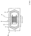
- FIG 3 shows a device according to the invention in side view.
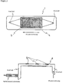
- Figure 4 shows the same device in supervision.
- the body of the measuring cell (1) consists of several polymethyl methacrylate individual parts.
- the cell interior (7) has an elongated, flat shape.
- the inlet and outlet openings (2, 3) are arranged at an obtuse angle of a triangle. With this arrangement it is achieved that no areas arise when liquid flows through the cell, in which liquid residues remain which do not participate in the volume flow.
- the cell shown has two counter electrodes (5) which have a flat, rod-like shape and are pressed into the upper part of the measuring cell.
- the counter electrodes (5) are connected to a voltage source via a common feed line (11). Both the working electrode and the counter electrodes are made of platinum in the example shown.
- An optical window (6) is located on the side of the measuring cell (1) opposite the working electrode.
- the cover (9) of the measuring cell consists of polymethyl methacrylate and is therefore transparent to visible radiation.
- FIG. 5 shows a further embodiment of a measuring cell (1) according to the invention.
- the structure of this measuring cell corresponds essentially to the measuring cell shown in FIG. 3 and FIG. A difference lies in the design of the counter electrode (5).
- this is arranged opposite the working electrode (4), however, has the shape of a rectangle with two rectangular recesses.
- the counter electrode (5) accordingly has segments which are both parallel and perpendicular to the direction of flow in the measuring cell.
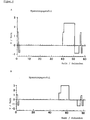
- Figure 6A shows a voltage profile which is suitable for carrying out an ECL reaction with the species tripropylamine and Ru (bpy) 32+ in a measuring cell according to the invention. While the measuring cell is filled with a buffer solution, a voltage of + 1.4 volts is applied for one second and a voltage of - 0.8 volts for another second. This preparation phase is used to create a defined surface condition of the working electrode. During the following 39 seconds, the measuring cell is filled with a mixture of analyte, reagent and buffer solution. There is a potential at the electrodes (e.g. 0 mV) at which no ECL reaction takes place, but which keeps the electrode in a reproducible state.
- a potential at the electrodes e.g. 0 mV
- a potential of + 1.4 volts is applied for one second to generate the ECL signal.
- the measuring cell is subsequently cleaned by applying a voltage of + 2.4 volts over 9.5 seconds and - 0.8 volts over 4 seconds. The cleaning process ends the measuring cycle.
- the voltage profile described can be used repeatedly in succession for subsequent measurements.
- FIG. 6B shows a voltage profile for operating a measuring cell according to the invention using a lower measuring voltage.
- the following table provides more precise information about the voltage curve over time and the liquids introduced into the measuring cell during the individual phases:
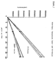
- FIGS. 7 and 8 show a comparison of the measuring cell according to the invention shown in FIGS. 3 and 4 (designated concept 3) with the measuring cell by Igen described in patent application WO 89/10551 for two different concentration ranges of analyte.
- the light signal shown on the ordinate in arbitrary units was obtained with a photomultiplier of the measuring device Origen 1.0 from IGEN.
- the abscissa of the figures indicates the concentration of TSH (thyroid stimulating hormone) contained in the sample.
- the measurements were carried out using 250 ⁇ l of the following mixture 50 ⁇ l buffer solution IP 50 ⁇ l bead suspension 50 ⁇ l biotinylated antibody (R1) 50 ⁇ l ruthenylated antibody (R2) 50 ⁇ l analyte were incubated for 16 minutes at room temperature and then 150 ul of the incubation batch were pumped into the measuring cell, where the beads were captured and washed with the aid of a magnet on the working electrode.
- composition of the solutions used is as follows:
Landscapes
- Health & Medical Sciences (AREA)
- Life Sciences & Earth Sciences (AREA)
- Chemical & Material Sciences (AREA)
- Immunology (AREA)
- Physics & Mathematics (AREA)
- Engineering & Computer Science (AREA)
- Analytical Chemistry (AREA)
- Biochemistry (AREA)
- General Health & Medical Sciences (AREA)
- General Physics & Mathematics (AREA)
- Pathology (AREA)
- Molecular Biology (AREA)
- Biomedical Technology (AREA)
- Urology & Nephrology (AREA)
- Chemical Kinetics & Catalysis (AREA)
- Hematology (AREA)
- Microbiology (AREA)
- Biotechnology (AREA)
- Cell Biology (AREA)
- Electrochemistry (AREA)
- Nuclear Medicine, Radiotherapy & Molecular Imaging (AREA)
- Plasma & Fusion (AREA)
- Food Science & Technology (AREA)
- Medicinal Chemistry (AREA)
- Investigating Or Analysing Materials By The Use Of Chemical Reactions (AREA)
- Investigating, Analyzing Materials By Fluorescence Or Luminescence (AREA)
- Spectrometry And Color Measurement (AREA)
- Optical Measuring Cells (AREA)
Applications Claiming Priority (2)
| Application Number | Priority Date | Filing Date | Title |
|---|---|---|---|
| DE4342942 | 1993-12-16 | ||
| DE4342942A DE4342942A1 (de) | 1993-12-16 | 1993-12-16 | Vorrichtung und Verfahren zur Erzeugung optisch detektierbarer Signale durch Anlegen elektrischer Potentiale an Probeflüssigkeiten |
Publications (2)
| Publication Number | Publication Date |
|---|---|
| EP0658760A1 true EP0658760A1 (fr) | 1995-06-21 |
| EP0658760B1 EP0658760B1 (fr) | 2002-07-24 |
Family
ID=6505191
Family Applications (1)
| Application Number | Title | Priority Date | Filing Date |
|---|---|---|---|
| EP94119574A Expired - Lifetime EP0658760B1 (fr) | 1993-12-16 | 1994-12-10 | Dispositif et méthode pour générer un signal optique par application de potentiels électriques aux échantillons liquides |
Country Status (7)
| Country | Link |
|---|---|
| EP (1) | EP0658760B1 (fr) |
| JP (1) | JP2975541B2 (fr) |
| AT (1) | ATE221195T1 (fr) |
| DE (2) | DE4342942A1 (fr) |
| DK (1) | DK0658760T3 (fr) |
| ES (1) | ES2181700T3 (fr) |
| PT (1) | PT658760E (fr) |
Cited By (6)
| Publication number | Priority date | Publication date | Assignee | Title |
|---|---|---|---|---|
| US6136268A (en) * | 1999-08-17 | 2000-10-24 | Orion Diagnostica | Method for luminescence measurements |
| EP1012590A4 (fr) * | 1997-03-25 | 2002-01-16 | Usf Filtration & Separations | Cellule electrochimique perfectionnee |
| CN102933967A (zh) * | 2010-06-09 | 2013-02-13 | 株式会社日立高新技术 | 试样分析装置和试样分析方法 |
| CN107290412A (zh) * | 2017-06-05 | 2017-10-24 | 南京理工大学 | 一种基于ZnTCPP@MOF的电化学免疫检测微囊藻毒素的方法 |
| CN109374535A (zh) * | 2018-10-10 | 2019-02-22 | 金华职业技术学院 | 一种用于光谱测量的电化学实验装置 |
| US20200150046A1 (en) * | 2017-08-01 | 2020-05-14 | Roche Diagnostics Operations, Inc. | Method of monitoring an operation of detection of an analyte in a liquid sample |
Families Citing this family (7)
| Publication number | Priority date | Publication date | Assignee | Title |
|---|---|---|---|---|
| US7300631B2 (en) * | 2005-05-02 | 2007-11-27 | Bioscale, Inc. | Method and apparatus for detection of analyte using a flexural plate wave device and magnetic particles |
| JP4587903B2 (ja) * | 2005-07-29 | 2010-11-24 | シチズンホールディングス株式会社 | 測定器具及びこれを用いた測定用キット、測定方法並びに測定装置 |
| US20090170210A1 (en) | 2005-10-28 | 2009-07-02 | Atsushi Fukunaga | Measuring device, measuring apparatus and method of measuring |
| ATE530895T1 (de) * | 2006-08-25 | 2011-11-15 | Hoffmann La Roche | Zelle zur durchführung elektrochemilumineszenter messungen |
| EP2816345A1 (fr) | 2013-06-19 | 2014-12-24 | Roche Diagniostics GmbH | Procédé d'électrochimioluminescence pour la détection d'un analyte dans un échantillon liquide et système d'analyse |
| JP6255216B2 (ja) * | 2013-11-05 | 2017-12-27 | 株式会社日立ハイテクノロジーズ | 電気化学測定装置 |
| CN105806828B (zh) * | 2015-10-29 | 2019-05-14 | 北京联众泰克科技有限公司 | 一种电化学发光免疫分析系统及其流通池组件 |
Citations (2)
| Publication number | Priority date | Publication date | Assignee | Title |
|---|---|---|---|---|
| WO1989010551A1 (fr) * | 1988-04-29 | 1989-11-02 | Igen, Inc. | Procede et appareil pour proceder a des mesures d'electrochimioluminescence |
| EP0525212A1 (fr) * | 1991-02-19 | 1993-02-03 | TDK Corporation | Methode d'analyse d'une substance electrochimioluminescente et appareil a cet effet |
Family Cites Families (3)
| Publication number | Priority date | Publication date | Assignee | Title |
|---|---|---|---|---|
| ZA893143B (en) * | 1988-04-28 | 1990-01-31 | Igen Inc | Apparatus for conducting a plurality or simultaneous measurements of electrochemiluminescent phenomena |
| JPH0225137A (ja) * | 1988-07-14 | 1990-01-26 | Fujitsu Ltd | 自動周波数制御方式 |
| JP3149255B2 (ja) * | 1991-02-19 | 2001-03-26 | ティーディーケイ株式会社 | 電気化学発光物質の分析方法及びそのための装置 |
-
1993
- 1993-12-16 DE DE4342942A patent/DE4342942A1/de not_active Ceased
-
1994
- 1994-12-10 EP EP94119574A patent/EP0658760B1/fr not_active Expired - Lifetime
- 1994-12-10 DK DK94119574T patent/DK0658760T3/da active
- 1994-12-10 AT AT94119574T patent/ATE221195T1/de not_active IP Right Cessation
- 1994-12-10 PT PT94119574T patent/PT658760E/pt unknown
- 1994-12-10 DE DE59410157T patent/DE59410157D1/de not_active Expired - Fee Related
- 1994-12-10 ES ES94119574T patent/ES2181700T3/es not_active Expired - Lifetime
- 1994-12-15 JP JP6312218A patent/JP2975541B2/ja not_active Expired - Fee Related
Patent Citations (2)
| Publication number | Priority date | Publication date | Assignee | Title |
|---|---|---|---|---|
| WO1989010551A1 (fr) * | 1988-04-29 | 1989-11-02 | Igen, Inc. | Procede et appareil pour proceder a des mesures d'electrochimioluminescence |
| EP0525212A1 (fr) * | 1991-02-19 | 1993-02-03 | TDK Corporation | Methode d'analyse d'une substance electrochimioluminescente et appareil a cet effet |
Cited By (10)
| Publication number | Priority date | Publication date | Assignee | Title |
|---|---|---|---|---|
| EP1012590A4 (fr) * | 1997-03-25 | 2002-01-16 | Usf Filtration & Separations | Cellule electrochimique perfectionnee |
| EP1736764A3 (fr) * | 1997-03-25 | 2007-05-09 | Lifescan, Inc. | Cellule électrochimique perfectionné |
| US6136268A (en) * | 1999-08-17 | 2000-10-24 | Orion Diagnostica | Method for luminescence measurements |
| CN102933967A (zh) * | 2010-06-09 | 2013-02-13 | 株式会社日立高新技术 | 试样分析装置和试样分析方法 |
| CN102933967B (zh) * | 2010-06-09 | 2015-03-18 | 株式会社日立高新技术 | 试样分析装置和试样分析方法 |
| CN107290412A (zh) * | 2017-06-05 | 2017-10-24 | 南京理工大学 | 一种基于ZnTCPP@MOF的电化学免疫检测微囊藻毒素的方法 |
| CN107290412B (zh) * | 2017-06-05 | 2019-09-13 | 南京理工大学 | 一种基于ZnTCPP@MOF的电化学免疫检测微囊藻毒素的方法 |
| US20200150046A1 (en) * | 2017-08-01 | 2020-05-14 | Roche Diagnostics Operations, Inc. | Method of monitoring an operation of detection of an analyte in a liquid sample |
| US11726044B2 (en) * | 2017-08-01 | 2023-08-15 | Roche Diagnostics Operations, Inc. | Method of monitoring an operation of detection of an analyte in a liquid sample |
| CN109374535A (zh) * | 2018-10-10 | 2019-02-22 | 金华职业技术学院 | 一种用于光谱测量的电化学实验装置 |
Also Published As
| Publication number | Publication date |
|---|---|
| DE4342942A1 (de) | 1995-06-22 |
| EP0658760B1 (fr) | 2002-07-24 |
| DK0658760T3 (da) | 2002-10-14 |
| JP2975541B2 (ja) | 1999-11-10 |
| PT658760E (pt) | 2002-12-31 |
| JPH07209189A (ja) | 1995-08-11 |
| DE59410157D1 (de) | 2002-08-29 |
| ES2181700T3 (es) | 2003-03-01 |
| ATE221195T1 (de) | 2002-08-15 |
Similar Documents
| Publication | Publication Date | Title |
|---|---|---|
| DE68928835T2 (de) | Verfahren zur Durchführung von Elektrochemilumineszenz-Messungen | |
| DE69722800T2 (de) | Probenanalyseverfahren mittels bestimmung einer funktion der spezifischen helligkeit | |
| DE69535223T2 (de) | Verfahren und Vorrichtung zu Elektrochemilumineszenz-Detektion magnetischer Partikel | |
| DE69233675T2 (de) | Verfahren und Vorrichtung zur Lumineszenzbestimmungen | |
| EP0658760B1 (fr) | Dispositif et méthode pour générer un signal optique par application de potentiels électriques aux échantillons liquides | |
| DE60029528T2 (de) | Trennungsverfahren von Substanzen durch Dielektrophoresis | |
| DE69312628T2 (de) | Verfahren zum Fördern von Flüssigkeiten | |
| EP1051621B1 (fr) | Procede d'analyse d'un echantillon selon un essai de reaction de liaison faisant appel a l'electrochimioluminescence | |
| DE69328231T2 (de) | Verfahren und Vorrichtung zur Ortung und zum Zählen von Fluoreszenz-Molekülen | |
| DE69518321T2 (de) | Verfahren und vorrichtung zum mischen von flüssigkeiten | |
| DE69232592T2 (de) | Automatisches kapillarelektroforesegerät | |
| DE2804657A1 (de) | Verfahren und vorrichtung zur durchfuehrung von immuntests | |
| CH713287B1 (de) | Elektrochemolumineszenz-Immunoassay-System und Durchflusszellen-Einheit davon. | |
| DE4216696C2 (de) | Verfahren und Vorrichtung zur Empfindlichkeits- und Selektivitätssteigerung bei Immuno-Assays, Molekül-Rezeptor-, DNA-komplementär-DNA- und Gast-Wirtsmolekül-Wechselwirkungs-Assays | |
| US5538687A (en) | Apparatus for generating optically detectable signals by applying electrical potentials to sample liquids | |
| DE69912403T2 (de) | Vorrichtung zur probenanalyse auf einem schwebenden tröpfchen | |
| DE3908918C2 (de) | Verfahren zur Bestimmung von Terbium oder Europium enthaltenden chemischen Komponenten | |
| EP0697106B1 (fr) | Procede electrochimiluminescent | |
| DE19903576A1 (de) | Quantitative Bestimmung von Analyten in einem heterogenen System | |
| DE69311613T2 (de) | Verfahren und Vorrichtung zur Reaktion von Partikeln | |
| JPH11352064A (ja) | 電気化学発光分析装置 | |
| DE102009015114B4 (de) | Vorrichtung nach Art einer elektrochemischen Kamera sowie Verfahren zur Herstellung und Verwendung der Vorrichtung | |
| DE19811582A1 (de) | Stabilisierung und Verstärkung von Elektrochemilumineszenz-Signalen | |
| US20060246603A1 (en) | Generation of chemiluminescence by hydrogen | |
| DE10202713A1 (de) | Biomolekularer Erkennungstest |
Legal Events
| Date | Code | Title | Description |
|---|---|---|---|
| PUAI | Public reference made under article 153(3) epc to a published international application that has entered the european phase |
Free format text: ORIGINAL CODE: 0009012 |
|
| AK | Designated contracting states |
Kind code of ref document: A1 Designated state(s): AT BE CH DE DK ES FR GB GR IE IT LI LU NL PT SE |
|
| 17P | Request for examination filed |
Effective date: 19951221 |
|
| RAP3 | Party data changed (applicant data changed or rights of an application transferred) |
Owner name: ROCHE DIAGNOSTICS GMBH |
|
| 17Q | First examination report despatched |
Effective date: 20000627 |
|
| GRAG | Despatch of communication of intention to grant |
Free format text: ORIGINAL CODE: EPIDOS AGRA |
|
| GRAG | Despatch of communication of intention to grant |
Free format text: ORIGINAL CODE: EPIDOS AGRA |
|
| GRAH | Despatch of communication of intention to grant a patent |
Free format text: ORIGINAL CODE: EPIDOS IGRA |
|
| GRAH | Despatch of communication of intention to grant a patent |
Free format text: ORIGINAL CODE: EPIDOS IGRA |
|
| GRAA | (expected) grant |
Free format text: ORIGINAL CODE: 0009210 |
|
| AK | Designated contracting states |
Kind code of ref document: B1 Designated state(s): AT BE CH DE DK ES FR GB GR IE IT LI LU NL PT SE |
|
| REF | Corresponds to: |
Ref document number: 221195 Country of ref document: AT Date of ref document: 20020815 Kind code of ref document: T |
|
| REG | Reference to a national code |
Ref country code: GB Ref legal event code: FG4D Free format text: NOT ENGLISH |
|
| REG | Reference to a national code |
Ref country code: CH Ref legal event code: EP |
|
| REG | Reference to a national code |
Ref country code: IE Ref legal event code: FG4D Free format text: GERMAN |
|
| REF | Corresponds to: |
Ref document number: 59410157 Country of ref document: DE Date of ref document: 20020829 |
|
| REG | Reference to a national code |
Ref country code: CH Ref legal event code: NV Representative=s name: F. HOFFMANN-LA ROCHE AG |
|
| REG | Reference to a national code |
Ref country code: DK Ref legal event code: T3 |
|
| GBT | Gb: translation of ep patent filed (gb section 77(6)(a)/1977) |
Effective date: 20021024 |
|
| REG | Reference to a national code |
Ref country code: GR Ref legal event code: EP Ref document number: 20020403516 Country of ref document: GR |
|
| REG | Reference to a national code |
Ref country code: PT Ref legal event code: SC4A Free format text: AVAILABILITY OF NATIONAL TRANSLATION Effective date: 20021023 |
|
| ET | Fr: translation filed | ||
| REG | Reference to a national code |
Ref country code: ES Ref legal event code: FG2A Ref document number: 2181700 Country of ref document: ES Kind code of ref document: T3 |
|
| PLBE | No opposition filed within time limit |
Free format text: ORIGINAL CODE: 0009261 |
|
| STAA | Information on the status of an ep patent application or granted ep patent |
Free format text: STATUS: NO OPPOSITION FILED WITHIN TIME LIMIT |
|
| 26N | No opposition filed |
Effective date: 20030425 |
|
| PGFP | Annual fee paid to national office [announced via postgrant information from national office to epo] |
Ref country code: PT Payment date: 20040929 Year of fee payment: 11 |
|
| PGFP | Annual fee paid to national office [announced via postgrant information from national office to epo] |
Ref country code: LU Payment date: 20041001 Year of fee payment: 11 |
|
| PGFP | Annual fee paid to national office [announced via postgrant information from national office to epo] |
Ref country code: IE Payment date: 20041022 Year of fee payment: 11 |
|
| PGFP | Annual fee paid to national office [announced via postgrant information from national office to epo] |
Ref country code: GR Payment date: 20041027 Year of fee payment: 11 |
|
| PGFP | Annual fee paid to national office [announced via postgrant information from national office to epo] |
Ref country code: DK Payment date: 20041109 Year of fee payment: 11 |
|
| PGFP | Annual fee paid to national office [announced via postgrant information from national office to epo] |
Ref country code: NL Payment date: 20041111 Year of fee payment: 11 |
|
| PGFP | Annual fee paid to national office [announced via postgrant information from national office to epo] |
Ref country code: SE Payment date: 20041202 Year of fee payment: 11 |
|
| PGFP | Annual fee paid to national office [announced via postgrant information from national office to epo] |
Ref country code: BE Payment date: 20050113 Year of fee payment: 11 |
|
| PG25 | Lapsed in a contracting state [announced via postgrant information from national office to epo] |
Ref country code: SE Free format text: LAPSE BECAUSE OF NON-PAYMENT OF DUE FEES Effective date: 20051211 |
|
| PG25 | Lapsed in a contracting state [announced via postgrant information from national office to epo] |
Ref country code: IE Free format text: LAPSE BECAUSE OF NON-PAYMENT OF DUE FEES Effective date: 20051212 |
|
| PG25 | Lapsed in a contracting state [announced via postgrant information from national office to epo] |
Ref country code: LU Free format text: LAPSE BECAUSE OF NON-PAYMENT OF DUE FEES Effective date: 20051231 Ref country code: BE Free format text: LAPSE BECAUSE OF NON-PAYMENT OF DUE FEES Effective date: 20051231 |
|
| PG25 | Lapsed in a contracting state [announced via postgrant information from national office to epo] |
Ref country code: DK Free format text: LAPSE BECAUSE OF NON-PAYMENT OF DUE FEES Effective date: 20060102 |
|
| PG25 | Lapsed in a contracting state [announced via postgrant information from national office to epo] |
Ref country code: PT Free format text: LAPSE BECAUSE OF NON-PAYMENT OF DUE FEES Effective date: 20060612 |
|
| PG25 | Lapsed in a contracting state [announced via postgrant information from national office to epo] |
Ref country code: NL Free format text: LAPSE BECAUSE OF NON-PAYMENT OF DUE FEES Effective date: 20060701 |
|
| REG | Reference to a national code |
Ref country code: DK Ref legal event code: EBP |
|
| EUG | Se: european patent has lapsed | ||
| REG | Reference to a national code |
Ref country code: PT Ref legal event code: MM4A Effective date: 20060612 |
|
| NLV4 | Nl: lapsed or anulled due to non-payment of the annual fee |
Effective date: 20060701 |
|
| REG | Reference to a national code |
Ref country code: IE Ref legal event code: MM4A |
|
| BERE | Be: lapsed |
Owner name: *ROCHE DIAGNOSTICS G.M.B.H. Effective date: 20051231 |
|
| PGFP | Annual fee paid to national office [announced via postgrant information from national office to epo] |
Ref country code: ES Payment date: 20071211 Year of fee payment: 14 |
|
| PGFP | Annual fee paid to national office [announced via postgrant information from national office to epo] |
Ref country code: AT Payment date: 20071107 Year of fee payment: 14 Ref country code: CH Payment date: 20071009 Year of fee payment: 14 Ref country code: IT Payment date: 20071215 Year of fee payment: 14 |
|
| PG25 | Lapsed in a contracting state [announced via postgrant information from national office to epo] |
Ref country code: GR Free format text: LAPSE BECAUSE OF NON-PAYMENT OF DUE FEES Effective date: 20020724 |
|
| PGFP | Annual fee paid to national office [announced via postgrant information from national office to epo] |
Ref country code: GB Payment date: 20071106 Year of fee payment: 14 |
|
| PGFP | Annual fee paid to national office [announced via postgrant information from national office to epo] |
Ref country code: DE Payment date: 20071228 Year of fee payment: 14 |
|
| PGFP | Annual fee paid to national office [announced via postgrant information from national office to epo] |
Ref country code: FR Payment date: 20071204 Year of fee payment: 14 |
|
| REG | Reference to a national code |
Ref country code: CH Ref legal event code: PL |
|
| GBPC | Gb: european patent ceased through non-payment of renewal fee |
Effective date: 20081210 |
|
| PG25 | Lapsed in a contracting state [announced via postgrant information from national office to epo] |
Ref country code: AT Free format text: LAPSE BECAUSE OF NON-PAYMENT OF DUE FEES Effective date: 20081210 |
|
| REG | Reference to a national code |
Ref country code: FR Ref legal event code: ST Effective date: 20090831 |
|
| PG25 | Lapsed in a contracting state [announced via postgrant information from national office to epo] |
Ref country code: LI Free format text: LAPSE BECAUSE OF NON-PAYMENT OF DUE FEES Effective date: 20081231 Ref country code: DE Free format text: LAPSE BECAUSE OF NON-PAYMENT OF DUE FEES Effective date: 20090701 Ref country code: CH Free format text: LAPSE BECAUSE OF NON-PAYMENT OF DUE FEES Effective date: 20081231 |
|
| PG25 | Lapsed in a contracting state [announced via postgrant information from national office to epo] |
Ref country code: GB Free format text: LAPSE BECAUSE OF NON-PAYMENT OF DUE FEES Effective date: 20081210 |
|
| REG | Reference to a national code |
Ref country code: ES Ref legal event code: FD2A Effective date: 20081211 |
|
| PG25 | Lapsed in a contracting state [announced via postgrant information from national office to epo] |
Ref country code: FR Free format text: LAPSE BECAUSE OF NON-PAYMENT OF DUE FEES Effective date: 20081231 Ref country code: ES Free format text: LAPSE BECAUSE OF NON-PAYMENT OF DUE FEES Effective date: 20081211 |
|
| PG25 | Lapsed in a contracting state [announced via postgrant information from national office to epo] |
Ref country code: IT Free format text: LAPSE BECAUSE OF NON-PAYMENT OF DUE FEES Effective date: 20081210 |