EP0659010B1 - Elektronisches Gerät mit Anzeigevorrichtung - Google Patents
Elektronisches Gerät mit Anzeigevorrichtung Download PDFInfo
- Publication number
- EP0659010B1 EP0659010B1 EP94119879A EP94119879A EP0659010B1 EP 0659010 B1 EP0659010 B1 EP 0659010B1 EP 94119879 A EP94119879 A EP 94119879A EP 94119879 A EP94119879 A EP 94119879A EP 0659010 B1 EP0659010 B1 EP 0659010B1
- Authority
- EP
- European Patent Office
- Prior art keywords
- display device
- hinge portions
- portions
- hinge
- apparatus body
- Prior art date
- Legal status (The legal status is an assumption and is not a legal conclusion. Google has not performed a legal analysis and makes no representation as to the accuracy of the status listed.)
- Expired - Lifetime
Links
Images




Classifications
-
- H—ELECTRICITY
- H04—ELECTRIC COMMUNICATION TECHNIQUE
- H04N—PICTORIAL COMMUNICATION, e.g. TELEVISION
- H04N1/00—Scanning, transmission or reproduction of documents or the like, e.g. facsimile transmission; Details thereof
- H04N1/21—Intermediate information storage
- H04N1/2166—Intermediate information storage for mass storage, e.g. in document filing systems
- H04N1/217—Interfaces allowing access to a single user
- H04N1/2175—Interfaces allowing access to a single user with local image input
-
- G—PHYSICS
- G06—COMPUTING OR CALCULATING; COUNTING
- G06F—ELECTRIC DIGITAL DATA PROCESSING
- G06F1/00—Details not covered by groups G06F3/00 - G06F13/00 and G06F21/00
- G06F1/16—Constructional details or arrangements
-
- G—PHYSICS
- G06—COMPUTING OR CALCULATING; COUNTING
- G06F—ELECTRIC DIGITAL DATA PROCESSING
- G06F3/00—Input arrangements for transferring data to be processed into a form capable of being handled by the computer; Output arrangements for transferring data from processing unit to output unit, e.g. interface arrangements
- G06F3/002—Specific input/output arrangements not covered by G06F3/01 - G06F3/16
-
- H—ELECTRICITY
- H04—ELECTRIC COMMUNICATION TECHNIQUE
- H04N—PICTORIAL COMMUNICATION, e.g. TELEVISION
- H04N1/00—Scanning, transmission or reproduction of documents or the like, e.g. facsimile transmission; Details thereof
- H04N1/00127—Connection or combination of a still picture apparatus with another apparatus, e.g. for storage, processing or transmission of still picture signals or of information associated with a still picture
-
- H—ELECTRICITY
- H04—ELECTRIC COMMUNICATION TECHNIQUE
- H04N—PICTORIAL COMMUNICATION, e.g. TELEVISION
- H04N1/00—Scanning, transmission or reproduction of documents or the like, e.g. facsimile transmission; Details thereof
- H04N1/00127—Connection or combination of a still picture apparatus with another apparatus, e.g. for storage, processing or transmission of still picture signals or of information associated with a still picture
- H04N1/00129—Connection or combination of a still picture apparatus with another apparatus, e.g. for storage, processing or transmission of still picture signals or of information associated with a still picture with a display device, e.g. CRT or LCD monitor
-
- H—ELECTRICITY
- H04—ELECTRIC COMMUNICATION TECHNIQUE
- H04N—PICTORIAL COMMUNICATION, e.g. TELEVISION
- H04N1/00—Scanning, transmission or reproduction of documents or the like, e.g. facsimile transmission; Details thereof
- H04N1/0035—User-machine interface; Control console
- H04N1/00352—Input means
- H04N1/00384—Key input means, e.g. buttons or keypads
-
- H—ELECTRICITY
- H04—ELECTRIC COMMUNICATION TECHNIQUE
- H04N—PICTORIAL COMMUNICATION, e.g. TELEVISION
- H04N1/00—Scanning, transmission or reproduction of documents or the like, e.g. facsimile transmission; Details thereof
- H04N1/0035—User-machine interface; Control console
- H04N1/00496—Constructional details of the interface or console not otherwise provided for, e.g. rotating or tilting means
-
- H—ELECTRICITY
- H04—ELECTRIC COMMUNICATION TECHNIQUE
- H04N—PICTORIAL COMMUNICATION, e.g. TELEVISION
- H04N1/00—Scanning, transmission or reproduction of documents or the like, e.g. facsimile transmission; Details thereof
- H04N1/04—Scanning arrangements, i.e. arrangements for the displacement of active reading or reproducing elements relative to the original or reproducing medium, or vice versa
- H04N1/203—Simultaneous scanning of two or more separate pictures, e.g. two sides of the same sheet
-
- H—ELECTRICITY
- H04—ELECTRIC COMMUNICATION TECHNIQUE
- H04N—PICTORIAL COMMUNICATION, e.g. TELEVISION
- H04N1/00—Scanning, transmission or reproduction of documents or the like, e.g. facsimile transmission; Details thereof
- H04N1/04—Scanning arrangements, i.e. arrangements for the displacement of active reading or reproducing elements relative to the original or reproducing medium, or vice versa
- H04N1/203—Simultaneous scanning of two or more separate pictures, e.g. two sides of the same sheet
- H04N1/2032—Simultaneous scanning of two or more separate pictures, e.g. two sides of the same sheet of two pictures corresponding to two sides of a single medium
- H04N1/2034—Simultaneous scanning of two or more separate pictures, e.g. two sides of the same sheet of two pictures corresponding to two sides of a single medium at identical corresponding positions, i.e. without time delay between the two image signals
-
- E—FIXED CONSTRUCTIONS
- E05—LOCKS; KEYS; WINDOW OR DOOR FITTINGS; SAFES
- E05D—HINGES OR SUSPENSION DEVICES FOR DOORS, WINDOWS OR WINGS
- E05D15/00—Suspension arrangements for wings
- E05D15/48—Suspension arrangements for wings allowing alternative movements
- E05D15/50—Suspension arrangements for wings allowing alternative movements for opening at either of two opposite edges
- E05D15/505—Suspension arrangements for wings allowing alternative movements for opening at either of two opposite edges by radial separation of the hinge parts at the hinge axis
-
- E—FIXED CONSTRUCTIONS
- E05—LOCKS; KEYS; WINDOW OR DOOR FITTINGS; SAFES
- E05D—HINGES OR SUSPENSION DEVICES FOR DOORS, WINDOWS OR WINGS
- E05D15/00—Suspension arrangements for wings
- E05D15/48—Suspension arrangements for wings allowing alternative movements
- E05D15/50—Suspension arrangements for wings allowing alternative movements for opening at either of two opposite edges
- E05D15/507—Suspension arrangements for wings allowing alternative movements for opening at either of two opposite edges by detachment of the hinge from the wing or the frame
-
- E—FIXED CONSTRUCTIONS
- E05—LOCKS; KEYS; WINDOW OR DOOR FITTINGS; SAFES
- E05Y—INDEXING SCHEME ASSOCIATED WITH SUBCLASSES E05D AND E05F, RELATING TO CONSTRUCTION ELEMENTS, ELECTRIC CONTROL, POWER SUPPLY, POWER SIGNAL OR TRANSMISSION, USER INTERFACES, MOUNTING OR COUPLING, DETAILS, ACCESSORIES, AUXILIARY OPERATIONS NOT OTHERWISE PROVIDED FOR, APPLICATION THEREOF
- E05Y2999/00—Subject-matter not otherwise provided for in this subclass
-
- G—PHYSICS
- G06—COMPUTING OR CALCULATING; COUNTING
- G06F—ELECTRIC DIGITAL DATA PROCESSING
- G06F2200/00—Indexing scheme relating to G06F1/04 - G06F1/32
- G06F2200/16—Indexing scheme relating to G06F1/16 - G06F1/18
- G06F2200/163—Indexing scheme relating to constructional details of the computer
- G06F2200/1631—Panel PC, e.g. single housing hosting PC and display panel
-
- H—ELECTRICITY
- H04—ELECTRIC COMMUNICATION TECHNIQUE
- H04N—PICTORIAL COMMUNICATION, e.g. TELEVISION
- H04N1/00—Scanning, transmission or reproduction of documents or the like, e.g. facsimile transmission; Details thereof
- H04N1/04—Scanning arrangements, i.e. arrangements for the displacement of active reading or reproducing elements relative to the original or reproducing medium, or vice versa
- H04N1/12—Scanning arrangements, i.e. arrangements for the displacement of active reading or reproducing elements relative to the original or reproducing medium, or vice versa using the sheet-feed movement or the medium-advance or the drum-rotation movement as the slow scanning component, e.g. arrangements for the main-scanning
-
- H—ELECTRICITY
- H04—ELECTRIC COMMUNICATION TECHNIQUE
- H04N—PICTORIAL COMMUNICATION, e.g. TELEVISION
- H04N1/00—Scanning, transmission or reproduction of documents or the like, e.g. facsimile transmission; Details thereof
- H04N1/04—Scanning arrangements, i.e. arrangements for the displacement of active reading or reproducing elements relative to the original or reproducing medium, or vice versa
- H04N1/19—Scanning arrangements, i.e. arrangements for the displacement of active reading or reproducing elements relative to the original or reproducing medium, or vice versa using multi-element arrays
- H04N1/191—Scanning arrangements, i.e. arrangements for the displacement of active reading or reproducing elements relative to the original or reproducing medium, or vice versa using multi-element arrays the array comprising a one-dimensional [1D] array
- H04N1/192—Simultaneously or substantially simultaneously scanning picture elements on one main scanning line
- H04N1/193—Simultaneously or substantially simultaneously scanning picture elements on one main scanning line using electrically scanned linear arrays, e.g. linear CCD arrays
-
- H—ELECTRICITY
- H04—ELECTRIC COMMUNICATION TECHNIQUE
- H04N—PICTORIAL COMMUNICATION, e.g. TELEVISION
- H04N2201/00—Indexing scheme relating to scanning, transmission or reproduction of documents or the like, and to details thereof
- H04N2201/0008—Connection or combination of a still picture apparatus with another apparatus
- H04N2201/0063—Constructional details
Definitions
- the present invention relates to an electronic apparatus having a display device (image display apparatus) as a part of the apparatus body, for example like image recording apparatus such as electronic filing systems (magnetooptical disk systems), word processors, personal computers, microfilm readers, microfilm reader printers, etc.
- image display apparatus image display apparatus
- image recording apparatus such as electronic filing systems (magnetooptical disk systems), word processors, personal computers, microfilm readers, microfilm reader printers, etc.
- Fig. 18 shows a schematic structure of an example of the electronic apparatus including a display device as a part of the apparatus body.
- the apparatus of this example is an electronic filing system and corresponds to what is disclosed in EP-A-0 364 827.
- Reference numeral 80 designates the apparatus body and 1 a display device set on the front surface of the apparatus body.
- This example employs a thin display device such as a liquid crystal display device in order to construct the entire apparatus in a compact size.
- the display device is fixed in a fixed angular posture at a predetermined angle to the apparatus body 80.
- Numeral 2 denotes a document mount portion projecting this side from the front surface of apparatus below the display device 1.
- Sheet documents S are loaded on the document mount portion 2.
- the loaded documents S are fed one by one from the top by a sheet feed roller 3, and a document is separated by a separator composed of a reversing roller 4 and a feeding roller 5 to be drawn into the apparatus body 80.
- a document S may be supplied by hand through the document mount portion 2 into a sheet feed port 2a, so that the hand-supplied document is drawn into the apparatus body 80 by the sheet feed roller 3 and the separator 4, 5.
- the document S drawn into the apparatus body 80 is conveyed from bottom to top in the apparatus body 80 through a path of from a pair of guide plates 12, 13, via a pair of conveying rollers 6, 7 and another pair of conveying rollers 8, 9 to a pinch-and convey belt apparatus 14, 15, and then is discharged onto a discharge tray portion 16 provided this side of the upper surface of the apparatus body 80.
- first and second image reading units 10, 11 set on either side of the conveying path photoelectrically read image information on the front side and on the back side of the document at first and second reading positions A, B, respectively, between the paired conveying rollers 6, 7 and the paired conveying rollers 8, 9.
- the first and second image reading units 10, 11 each consist of a document illumination light source, mirrors for guiding image light, an imaging lens, and an image reading sensor such as CCD.
- the image information of the document photoelectrically read by the image reading units 10, 11 is recorded in a magnetooptical disk as a detachable recording medium in a magnetooptical recording apparatus 17.
- the recording medium may be one fixed in the apparatus body, such as a hard disk.
- the thus read image information is displayed on the display apparatus 1, whereby whether reading is fine or not can be checked.
- the image information recorded in the recording medium may be displayed on the display device 1 while retrieving it with necessity.
- the information may also be output as a hard copy by a printing mechanism not shown.
- Signals for retrieving information for retrieval and for operation of apparatus are supplied through a keyboard not shown and key switches 20 activated according to the contents displayed on the display device 1.
- the key switches 20 are arranged in the front portion of display device 1 near the lower edge.
- Numeral 18 is an electrical-component portion including a print-circuit board etc. for controlling the power source and the apparatus.
- the display device 1 in the apparatus of the above example is set in the fixed angular posture at the predetermined angle on the front surface of the apparatus body 80, it is convenient if the display device 1 is arranged as pivotable relative to the apparatus body 80 so as to properly adjust (or tilt) up and down (or, left and right) into an elevation posture or into a depression posture at an appropriate angle (or into a leftward posture or a rightward posture at an appropriate angle) in order to facilitate observation of the image displayed on the display device 1 in accordance with the operator's sitting height or conditions of illumination light, etc.
- Fig. 19 shows an apparatus in which the display device 1 is arranged to tilt into an elevation posture or into a depression posture at an appropriate angle as shown by a chain double-dashed line 1a or 1b about a support axis a on the upper edge side of the display device 1
- Fig. 20 shows an apparatus in which the display device 1 is arranged to tilt into an elevation posture or into a depression posture at an appropriate angle as shown by a chain double-dashed line 1a or 1b about a support axis b on the lower edge side of the display device 1.
- the lower edge of the display device 1 is fixed at the position, so that the lower edge is always an obstruction, which makes the problem pronounced.
- the operator can move the display device 1 into the depression posture 1b to bring the lower edge of the display device 1 to that side of the document mount portion 2 so as not to be an obstruction.
- the above problem can be avoided to some extent upon setting the documents onto the document mount portion 2 or upon supplying the document by hand, though the operator is required to perform a troublesome operation to tilt the display device 1 into the depression posture 1b.
- This case has another problem that the control of the key switches 20 is not easy, because the position of the key switches 20 arranged in the lower end portion of display device 1 is shifted to that side because of the tilting of the display device 1.
- a portable electronic apparatus comprising a container, wherein said container contains a movable flat type display device movable between a retracted position and a pulled out position, the display screen of said flat type display device being parallel to a front surface of said container when in said contracted position, said flat type display device being movably mounted in said container by a moving mechanism comprising a first member pivotally mounted on a frame of said container at a first pivot point, a second member pivotally mounted on said first member at a second pivot point which is spaced from said first pivot point, an supporting said flat type display device.
- the thus formed pivots are not releasable.
- US-A-5 103 376 discloses a computer comprising a keyboard portion and a display portion interconnected in a manner which provides dual positions operational.
- the interconnection mechanism comprises two hinges, wherein each hinge has two pivot points connected to the keyboard portion and the display portion, respectively. Further, each hinge is provided with a locking mechanism to maintain two modes or operating positions.
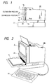
- Fig. 2 is a perspective view to show an appearance of the apparatus of the present embodiment.
- the apparatus of this example is also an electronic filing system as the above-described apparatus in Fig. 18 was.
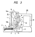
- Fig. 3 is a schematic, vertical cross-sectional side view of the apparatus.
- the same constituents and portions as those in the above-described apparatus in Fig. 18 are denoted by the same reference numerals and redundant description will be omitted.
- reference numeral 90 designates a keyboard, and signals for retrieving information for retrieval and for operation of apparatus are supplied through the keyboard 90 into the apparatus body. Also, the signals may be supplied through key switches 20 activated according to the contents displayed on the display device 1. Operations and functions for reading, recording, displaying, etc. of image information of document S are the same as those of the above-described apparatus of Fig. 18.
- the display device 1 is tilted in the manner as described with Fig. 1.
- the tilting mechanism is next described.
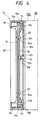
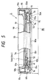
- Fig. 4 is a vertical cross-sectional view of the portion of the display device, which shows a state in which the display device 1 is held in the standard angular posture in which the display device 1 is hooked both on hinge portions 70A, 70B on the upper side and on the lower side on the front surface of the apparatus body 80.
- Fig. 5 is a plan view, partly broken, of the portion of the display device.
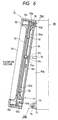
- Fig. 6 shows a state in which the display device 1 is released from the hooked state on the lower hinge portions 70B and then is rotated upward from the standard angular posture of Fig. 4 about the upper hinge portions 70A so as to be tilted in the elevation posture at a desired angle.
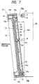
- Fig. 7 shows a state in which the display device 1 is released from the hooked state on the upper hinge portions 70A and then is rotated downward from the standard angular posture of Fig. 4 about the lower hinge portions 70B so as to be tilted in the depression posture at a desired angle.
- Fig. 8 is a front elevation of a front panel 80a of the apparatus body 80 to which the display device 1 is mounted.
- the hinge portions 70A, 70A and 70B, 70B have the same structure.
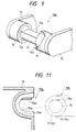
- Fig. 9 is a perspective view, partly broken, of one hinge portion.
- each hinge portion consists of a pair of left and right projecting portions (brackets) 71, 72, friction outer casings 73, 74 arranged as opposed to each other on inner surfaces of distal end portions of the pair of left and right projecting portions 71, 72, inner rings 73a, 74a internally fitting with the friction outer casings 73, 74, and a D-cut shaft (support shaft) 75 fixed between the inner rings 73a and 74a.
- Numeral 75a represents a D-cut surface of the shaft 75.
- the D-cut surfaces 75a of support shafts 75, 75 of upper hinge portions 70A, 70A face up, while the D-cut surfaces 75a of support shafts 75, 75 of lower hinge portions 70B, 70B face down.
- the inner rings 73a, 74a are rotatable with application of a certain load on the friction external casings 73, 74. Accordingly, the D-cut shaft 75 as a support shaft integral with the inner rings 73a, 74a is also rotatable with application of a certain load.
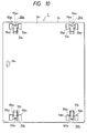
- Fig. 10 is a rear elevation of the display device 1.
- the U-shaped recess portions have the same shape.
- Fig. 11 is an enlarged, transverse, cross-sectional side view of one U-shaped recess portion.
- Correspondently put into larger-diameter recess portions 55a 1 , 55a 1 (55b 1 , 55b 1 ) on the both end sides of each U-shaped recess portion are the distal ends of the pair of left and right projecting portions 71, 72 and the friction outer casings 73, 74 of the hinge portion 70A (70B).
- the D-cut shaft 75 is put into a middle recess portion 55a 2 (55b 2 ) in correspondence therewith.
- 55a 3 (55b 3 ) is a portion correspondently associated with the D-cut surface 75a of the D-cut shaft 75.
- numeral 50 designates a thin display using a liquid crystal etc., set in a front frame of the housing cover 55, and 51 a base to which the display 50 is fixed.
- the base is supported on the housing cover 55 by fixing it on inward bosses 55c integrally provided with the housing cover 55, in an incorporated manner.
- Numeral 54 denotes a slide plate disposed between the base 51 and the back panel 55 1 of the housing cover 55.
- Fig. 12 is a rear elevation of the inside of the display device 1 to show the back side of the slide plate 54, removing the back panel 55 1 of the housing cover 55.
- This slide plate 54 is slidable in vertical directions of arrows a, b in Fig. 12 within the range of the length of elongate holes 54a, because stepped pins 52 provided at the four corners on the back surface of the base 51 are fit in the associated vertically elongate holes 54a provided at the four corners of the slide plate 54.
- a pair of claw members 57a, 57a extend upward on the both, left and right, sides in the upper edge portion of the slide plate 54, while a pair of claw members 57b, 57b extend downward in the both, left and right, edge portions on the lower edge side.
- two, first and second, control levers 62, 63 are provided on upper and lower sides on the back surface and on the left side of the base 51 in Fig. 12.
- the first control lever 62 is rotatable clockwise or counterclockwise about a pin shaft 64 planted in the base 51, and one arm 62a is fit in a vertical window 55 2 provided on the side wall of the housing cover 55 so as to be exposed as a control knob to the outside.
- Another arm 62b is a bifurcated fork, and a first pin 66 planted on the back surface of the slide plate 54 is located between upper and lower legs 62b 1 and 62b 2 of the bifurcated fork 62b.
- the first control lever 62 is always biased in the direction of counterclockwise rotation about the pin shaft 64 by a spring 59, and is kept to be stopped in contact with a stopper pin 68 in a free state. In this state, the upper surface of the lower leg 62b 2 of the bifurcated fork 62b is in contact with the lower surface of the first pin 66.
- the second control lever 63 is rotatable clockwise or counterclockwise about a pin shaft 65 planted in the base 51, and one arm 63a is fit in a vertical window 55 3 provided on the side wall of the housing cover 55 so as to be exposed as a control knob to the outside.
- Another arm 63b is a bifurcated fork, and a second pin 67 planted on the back surface of the slide plate 54 is located between upper and lower legs 63b 1 and 63b 2 of the bifurcated fork 63b.
- the second control lever 63 is always biased in the direction of clockwise rotation about the pin shaft 65 by a spring 60, and is kept to be stopped in contact with a stopper pin 69 in a free state. In this state, the lower surface of the upper leg 63b 1 of the bifurcated fork 63b is in contact with the upper surface of the second pin 67.
- Numeral 51a denotes a louvering portion provided in the base 51 at a nearly middle position between the first and second control levers 62, 63 set on the upper side and on the lower side, and 61 a lock lever rockable back and forth about a pin 51b planted in the louvering portion 51a with respect to the slide plate 54.
- the lock lever 61 is always biased in the direction of counterclockwise rotation in Fig. 5 by a biasing spring not shown.
- 54b, 54c are two, first and second, lock holes provided on the upper side and on the lower side in the slide plate 54, and a locking hook 61b at the distal end of one arm 61a of the lock lever 61 is to be engaged with or disengaged from either one of the two holes.
- the above ascending movement a of the slide plate 54 causes the second lock hole 54c on the lower side to face the locking hook 61b of the lock lever 61, so that the locking hook 61b drops into the second lock hole 54c to be engaged therewith, thus keeping the slide plate 54 locked at the up position.
- the upward claw members 57a, 57a are raised to make the upper U-shaped recess portions 55a, 55a completely closed by the claw members 57a, 57a.
- the downward claw members 57b, 57b are also raised, the opening portions of the lower U-shaped recess portions 55b, 55b are kept completely open.
- a mounting operation of the display device 1 onto the apparatus body 80 is carried out as follows. As described in above (ii), the operation of the first control lever 62 lowers (or moves in the direction of b) the slide plate 54 so as to completely open the upper U-shaped recess portions 55a, 55a of the display device 1.
- a jig such as a screwdriver is put into the hole 55 4 provided in the back panel 55 1 of the housing cover 55 of the display device 1 to push the other arm 61c of the lock lever 61.
- This locking release causes the slide plate 54 to ascend (or move in the direction of a) with counterclockwise rotation of the first lever 62 due to the spring 59 and then to return to the middle height position of Fig. 12.
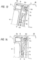
- the ascent of the slide plate 54 to the middle height position causes the upward claw members 57a, 57a of the slide plate 54 to close approximately lower half portions of the opening portions of the upper U-shaped recess portions 55a, 55a, as shown in Fig. 14, thereby stopping unhooking of the upper U-shaped recess portions 55a, 55a from the hinge portions 70A, 70A.
- the second control lever 63 is rotated to raise (or move in the direction of a) the slide plate 54, as in above (iii). This raises the downward claw members 57b, 57b so as to leave the opening portions of the lower U-shaped recess portions 55b, 55b, thereby completely opening the opening portions of the lower U-shaped recess portions 55b, 55b. Then the display device 1 is rotated to the front panel 80a of the apparatus body 80 about the upper hinge portions 70A, 70A to make hooking engagement between the lower U-shaped recess portions 55b, 55b and the lower hinge portions 70B, 70B.
- the pin 76 provided on the front panel 80a of the apparatus body 80 matches with the hole 55 4 provided on the back panel 55 1 of the housing cover 55 in the display device 1, so that the distal end of the pin 76 goes into the display device 1, whereby the distal end of the pin 76 pushes the other arm 61c of the lock lever 61.
- This locking release causes the slide plate 54 to descend (or move in the direction of b) by its own weight and then to return to the middle height position of Fig. 12.
- This descent of the slide plate 54 to the middle height position causes the downward claw members 57b, 57b of the slide plate 54 to close approximately upper halves of the opening portions of the lower U-shaped recess portions 55b, 55b, thereby stopping unhooking of the lower U-shaped recess portions 55b, 55b from the lower hinge portions 70B, 70B.
- the upper and lower claw members 57a, 57a and 57b, 57b come to stop disengagement of the upper U-shaped recess portions 55a, 55a from the upper hinge portions 70A, 70A and disengagement of the lower U-shaped recess portions 55b, 55b from the lower hinge portions 70B, 70B, whereby the display device 1 is mounted and held in the standard angular posture as shown in Fig. 4 on the front panel 80a of the apparatus body 80.
- the second control lever 63 is first rotated as in above (iii) to raise (or move in the direction of a) the slide plate 54 so as to make the opening portions of the lower U-shaped recess portions 55b, 55b completely open, whereby the disengagement stop is released between the lower U-shaped recess portions 55b, 55b and the lower hinge portions 70B, 70B, and then the display device 1 is rotated into the elevation posture at a desired angle about the upper hinge portions 70A, 70A.
- the rotation of the display device 1 into the above elevation posture causes the display device 1 to go away from the pin 76 on the apparatus body 80, so that the press on the arm 61c of lock lever 61 is released and the locking hook 61b drops into the second lock hole 54c in the slide plate 54 thus raised (or moved in the direction of a) to lock the slide plate 54 at the ascent position.
- the display device 1 Since the support shafts 75, 75 of the upper hinge portions 70A, 70A are rotatable with application of a certain load, as described previously, the display device 1 is stably held overcoming its own weight at the position of elevation posture as adjusted at a desired angle about the support shafts 75, 75.
- the display device 1 When the display device 1 is returned from the elevation posture at the desired angle to the standard angular posture of Fig. 4, the display device 1 is reversely rotated about the upper hinge portions 70A, 70A.
- the lower U-shaped recess portions 55b, 55b with the opening portions being open come to engage with the lower hinge portions 70B, 70B.
- the pin 76 pushes the lock lever 61 so as to force the locking hook 61b out of the second lock hole 54c, which releases the locking at the ascent position of the slide plate 54 to bring the slide plate 54 back to the middle height position.
- the first control lever 62 is first rotated as in above (ii) to lower (or move in the direction of b) the slide plate 54 so as to make the opening portions of the upper U-shaped recess portions 55a, 55a completely open, whereby the disengagement stop is released between the upper U-shaped recess portions 55a, 55a and the upper hinge portions 70A, 70A, and then the display device 1 is rotated into the depression posture at a desired angle about the lower hinge portions 70B, 70B.
- the rotation of the display device 1 into the above depression posture causes the display device 1 to go away from the pin 76 on the apparatus body 80, so that the press on the arm 61c of lock lever 61 is released and the locking hook 61b drops into the first lock hole 54b in the slide plate 54 thus lowered (or moved in the direction of b) to lock the slide plate 54 at the descent position.
- the display device 1 Since the support shafts 75, 75 of the lower hinge portions 70B, 70B are rotatable with application of a certain load, as described previously, the display device 1 is stably held overcoming its own weight at the position of depression posture as adjusted at a desired angle about the support shafts 75, 75.
- the display device 1 When the display device 1 is returned from the depression posture at the desired angle to the standard angular posture of Fig. 4, the display device 1 is reversely rotated about the lower hinge portions 70B, 70B.
- the upper U-shaped recess portions 55a, 55a with the opening portions being open come to engage with the upper hinge portions 70A, 70A.
- the pin 76 pushes the lock lever 61 so as to force the locking hook 61b out of the first lock hole 54b, which releases the locking at the descent position of the slide plate 54 to bring the slide plate 54 back to the middle height position.
- the present embodiment employs a ratchet mechanism in the hinge portion 70A (70B) for supporting the display device 1 on the front panel 80a of the apparatus body 80, whereby the support shaft 75 can freely rotate only in one direction.
- Fig. 15 is a broken side view of a hinge portion, and Fig. 16 a broken plan view thereof.
- the support shaft 75 of the hinge portion 70A is set between left and right projecting portions (brackets) 71, 72 so as to be rotatable about a shaft 158.
- Ratchets 156, 156 are incorporated with the support shaft 75.
- Numeral 157 designates a plate spring having a pawl 157a, the base of which is mounted on a seat 154a of the projecting portion 71, 72.
- the ratchet 156 cannot rotate counterclockwise but can rotate only clockwise. Accordingly, when the U-shaped recess portion 55a on the display device 1 is engaged with the D-cut surface 75a of the support shaft 75 in the hinge portion 70A on the apparatus body 80, i.e., when the support shaft 75 and the display device 1 are incorporated with each other, a motion is free in the direction to tilt the display device 1, but no motion is allowed in the returning direction.
- the stiffness is increased in the direction to return the display device 1, and the operability is improved, because, in pressing a key switch 20 in the display device 1, there is no movement of the display device 1 even with a too strong force applied thereon. Further, the operability to tilt the display device 1 is also excellent, because it can be lightly moved in the direction to tilt.
- the operator moves the control knob, as with the previously described apparatus of embodiment 1, to move the slide plate 54, thus the claw members 57a, further upward from the state of Fig. 15.
- This motion causes the fore end 57a of the claw member 57a to push a portion 157b of the plate spring 157 so as to disengage the pawl 157a from the ratchet 156, whereby the support shaft 75 becomes rotatable counterclockwise so as to allow the display device to be returned to the original position.
- An apparatus of the present embodiment is so arranged that a C-shaped frame 100 is provided on the front surface side of the apparatus body 80 with legs being connected at the lower ends thereof to the apparatus body 80 so as to be rotatable about lower hinge portions 70B and that the display device 1 is set in the C-shaped frame 100 with the upper side being connected to the frame 100 so as to be rotatable about an upper hinge portion 70A relative to the frame 100.
- the each lower hinge portion 70B is connected to the apparatus body 80 through a friction member so that the C-shaped frame 100 is stably held in a rotated state when it is rotated relative to the apparatus body 80.
- the upper hinge portion 70A is connected to the frame 100 through a friction member so that a rotated state of the display device 1 is stably held when the display device 1 is rotated relative to the C-shaped frame 100.
- the display device 1 is held in the standard angular posture as shown in Fig. 17A when the C-shaped frame 100 is rotated about the lower hinge portions 70B to be folded onto the front surface of the apparatus body 80 and when the display device 1 is rotated about the upper hinge portion 70A to be folded into the C-shaped frame 100.
- the display device 1 folded in the C-shaped frame 100 is rotated upward to a desired angle about the upper hinge portion 70A while keeping the C-shaped frame 100 as folded on the front surface of the apparatus body 80, as shown in Fig. 17B.
- the C-shaped frame 100 is rotated downward to a desired angle about the lower hinge portion 70B while keeping the display device 1 as folded in the C-shaped frame 100, as shown in Fig. 17C.
- the key switches 20 will never be drawn backward but come forward upon tilting, which would never degrade the operability of key switches 20.
- an amount of movement of the key switches 20 is about a half of that for example where the display device is arranged to be tilted only about the upper support shaft.
- hinge portions (70A, 70B) and the U-shaped recess portions (55a, 55b) to be engaged with each other are relative, they may be reversed from the relation in the embodiments in such a manner that the hinge portions (70A, 70B) are provided on the display device 1 while the U-shaped recess portions (55a, 55b) on the apparatus body 80.
Landscapes
- Engineering & Computer Science (AREA)
- Multimedia (AREA)
- Signal Processing (AREA)
- Theoretical Computer Science (AREA)
- Human Computer Interaction (AREA)
- Physics & Mathematics (AREA)
- General Engineering & Computer Science (AREA)
- General Physics & Mathematics (AREA)
- Devices For Indicating Variable Information By Combining Individual Elements (AREA)
Claims (12)
- Elektronisches Gerät mit einer Flachanzeigevorrichtung (1), umfassend:einen Gerätekörper (80); undScharnierteile (70A, 70B) zum schwenkbaren Koppeln der Anzeigevorrichtung (1) mit dem Gerätekörper (80);
dadurch gekennzeichnet, daß
das Gerät außerdem aufweist:erste Scharnierteile (70A) zum direkten Koppeln eines Endes der Anzeigevorrichtung (1) mit dem Gerätekörper (80), wobei die ersten Scharnierteile (70A) umstellbar sind zwischen einem Zustand, in welchem sie den Gerätekörper (80) und die Anzeigevorrichtung (1) verbinden, und einem Zustand, in welchem sie den Gerätekörper (80) nicht mit der Anzeigevorrichtung (1) verbinden;zweite Scharnierteile (70B) zum direkten schwenkbaren Koppeln des anderen Endes der Anzeigevorrichtung (1) mit dem Gerätekörper (80), wobei die zweiten Scharnierteile (70B) umstellbar sind zwischen einem Zustand, in welchem sie den Gerätekörper (80) mit der Anzeigevorrichtung (1) verbinden, und einem Zustand, in welchem sie den Gerätekörper (80) nicht mit der Anzeigevorrichtung (1) verbinden;
wobeider erste Scharnierteil (70A) die Anzeigevorrichtung (1) in einer ersten Stellung hält, wenn die Anzeigevorrichtung (1) und der Gerätekörper (80) direkt über die erste Scharniereinrichtung gekoppelt ist, hingegen über die zweiten Scharnierteile (70B) nicht gekoppelt sind, undder zweite Scharnierteil (70B) die Anzeigevorrichtung (1) in einer zweiten, von der ersten Stellung verschiedenen Stellung hält, wenn die Anzeigevorrichtung (1) und der Gerätekörper (80) über die zweiten Scharnierteile gekoppelt sind, hingegen die ersten Scharnierteile (70A) nicht gekoppelt sind undeine Einrichtung vorgesehen ist, um die Kopplungen der ersten Scharnierteile (70A) oder der zweiten Scharnierteile (70B) selektiv zu lösen. - Gerät nach Anspruch 1, bei dem
die ersten Scharnierteile (70A) und die zweiten Scharnierteile (70B) in dem oberen bzw. unteren Teil der Anzeigevorrichtung angeordnet sind, wodurch eine Anzeigefläche der Anzeigevorrichtung nach oben oder nach unten geneigt werden kann. - Gerät nach Anspruch 1, bei dem
die ersten Scharnierteile (70A) in dem linken und dem rechten Bereich der Anzeigevorrichtung vorgesehen sind, wodurch eine Anzeigefläche der Anzeigevorrichtung nach links oder nach rechts geneigt werden kann. - Gerät nach einem der vorhergehenden Ansprüche, bei dem die ersten Scharnierteile (70A) und die zweiten Scharnierteile (70B) jeweils eine einen Drehpunkt bildende Welle (75) aufweisen, ferner ein Halterungsglied (55, 55a, 55b) zum drehbaren Haltern der Welle (75) und zum Haltern der Welle (75) in einer beliebigen Drehstellung, wobei die Welle (75) mit dem Halterungsglied (55, 55a, 55b) in Eingriff bringbar oder von ihm lösbar ist.
- Gerät nach Anspruch 1, 2 oder 4, bei dem die
ersten Scharnierteile (70A) und die zweiten Scharnierteile (70B) zum Drehen der Anzeigevorrichtung (1) jeweils einem Vorsprung (71, 72) mit einer einer Lagerungswelle der Anzeigevorrichtung (1) bildenden Welle (75) aufweisen, ferner einen damit in Eingriff tretenden U-förmigen Ausnehmungsteil (55a, 55b), ein Klauenglied (57a, 57b), verschieblich ausgebildet zum Schließen eines Öffnungsbereichs des U-förmigen Ausnehmungsteils (55a, 55b), und eine Steuereinrichtung (72, 73) zum Steuern einer Bewegung des Klauenglieds (55a, 55b) in der Weise, daß in einem Zustand, in welchem die Anzeigevorrichtung (1) mit sowohl den ersten Scharnierteilen (70A) als auch den zweiten Scharnierteilen (70B) im oberen bzw. im unteren Bereich der Vorrichtung in Eingriff steht, das Klauenglied (57a, 57b) verschoben werden kann, um den Öffnungsbereich des U-förmigen Ausnehmungsteils (55a, 55b) zu öffnen, so daß die obere oder die untere Welle (75), die mit dem U-förmigen Ausnehmungsteil (55a, 55b) in Eingriff steht, gelöst werden kann, und das in einem Zustand, in welchem die Anzeigevorrichtung (1) gekippt ist, während ein Teil von dem ersten und dem zweiten Scharnierteil (70a, 70b) gelöst ist, die in den Vorsprung (71, 72) vorgesehene Welle (75) als Halterungswelle so gehalten wird, daß sie sich nicht aus dem Eingriffszustand mit dem U-förmigen Ausnehmungsteil (55a, 55b) löst. - Gerät nach einem der vorhergehenden Ansprüche, bei dem die ersten Scharnierteile (70A) und die zweiten Scharnierteile (70B) zum Kippen der Anzeigevorrichtung (1) sich zum Kippen der Anzeigevorrichtung (1) frei in einer Richtung drehen, hingegen die Anzeigevorrichtung (1) in einer Umkehrrichtung, dem Lösen durch die Löseeinrichtung fixieren.
- Gerät nach einem der vorhergehenden Ansprüche, bei dem
die Anzeigevorrichtung (1) auf ihrer Frontseite eine Tastatur (20) aufweist. - Gerät nach Anspruch 1,
umfassend:einen Dokumentenauflagetisch (2) unterhalb der Anzeigevorrichtung (1);eine Blatt-Transporteinrichtung (3-9) zum Transportieren eines auf dem Dokumentenauflagetisch (2) plazierten Dokuments (S);eine Leseeinrichtung (10, 11) zum Lesen eines auf dem so transportierten Dokument (S) befindlichen Bildes, um das Bild in ein Bildsignal umzuwandeln;eine Einrichtung zum Anzeigen des Bildes auf der Anzeigevorrichtung (1) auf der Grundlage des von der Leseeinrichtung (10, 11) kommenden Bildsignals; undeine Einrichtung (17) zum Aufzeichnen des Bildsignals auf einem Aufzeichnungsmedium. - Gerät nach Anspruch 8, bei dem
ein Schlüsselschalter (20) an der Frontseite der Anzeigevorrichtung (1) vorgesehen ist. - Gerät nach einem der vorhergehenden Ansprüche, bei dem
die Anzeigevorrichtung (1) eine Flüssigkristallanzeigevorrichtung ist. - Gerät nach einem der vorhergehenden Ansprüche, bei dem
die Anzeigevorrichtung (1) an dem Gerätekörper (80) angebracht oder von ihm gelöst werden kann. - Gerät nach einem der vorhergehenden Ansprüche mit einer Leseeinrichtung (62) zum Lösen der Scharnierverbindung der ersten Scharnierteile (70A) oder der zweiten Scharnierteile (70B), und eine zweite Löseeinrichtung (63) zum Lösen der Scharnierkopplung der anderen Scharniereinrichtung, wobei die Löseeinrichtungen (62, 63) jeweils ein von Hand bedienbares Element aufweisen.
Applications Claiming Priority (3)
| Application Number | Priority Date | Filing Date | Title |
|---|---|---|---|
| JP343145/93 | 1993-12-15 | ||
| JP34314593A JP3170986B2 (ja) | 1993-12-15 | 1993-12-15 | チルト可能なディスプレイ装置を有する機器 |
| JP34314593 | 1993-12-15 |
Publications (2)
| Publication Number | Publication Date |
|---|---|
| EP0659010A1 EP0659010A1 (de) | 1995-06-21 |
| EP0659010B1 true EP0659010B1 (de) | 2000-05-10 |
Family
ID=18359268
Family Applications (1)
| Application Number | Title | Priority Date | Filing Date |
|---|---|---|---|
| EP94119879A Expired - Lifetime EP0659010B1 (de) | 1993-12-15 | 1994-12-15 | Elektronisches Gerät mit Anzeigevorrichtung |
Country Status (4)
| Country | Link |
|---|---|
| US (1) | US5719645A (de) |
| EP (1) | EP0659010B1 (de) |
| JP (1) | JP3170986B2 (de) |
| DE (1) | DE69424384T2 (de) |
Cited By (1)
| Publication number | Priority date | Publication date | Assignee | Title |
|---|---|---|---|---|
| US11960329B2 (en) | 2019-11-17 | 2024-04-16 | Hewlett-Packard Development Company, L.P. | Computing devices with retractable hinges |
Families Citing this family (10)
| Publication number | Priority date | Publication date | Assignee | Title |
|---|---|---|---|---|
| JP2000505396A (ja) | 1996-03-02 | 2000-05-09 | フォルクスワーゲン・アクチェンゲゼルシャフト | 自動車の多機能装置 |
| US5979764A (en) * | 1996-07-22 | 1999-11-09 | Symbol Technologies, Inc. | Hand-held electronic apparatus with pivoting display |
| US6654068B1 (en) | 2000-01-04 | 2003-11-25 | International Business Machines Corporation | Brake mechanism for controlling the tilt of a computer display |
| US7387572B2 (en) * | 2003-09-11 | 2008-06-17 | Wms Gaming Inc. | Gaming machine with a trunnion mounted display |
| JP4523600B2 (ja) * | 2003-11-14 | 2010-08-11 | エルジー エレクトロニクス インコーポレイティド | 冷蔵庫 |
| JP4246712B2 (ja) * | 2005-03-30 | 2009-04-02 | 富士通テン株式会社 | 電子機器 |
| TWI302324B (en) | 2005-03-30 | 2008-10-21 | Fujitsu Ten Ltd | Tilting apparatus and electronic apparatus |
| US7495846B1 (en) * | 2006-09-12 | 2009-02-24 | Kantek, Inc. | Adjustable computer monitor optical device |
| JP4317210B2 (ja) | 2006-12-07 | 2009-08-19 | 東芝テック株式会社 | 表示装置 |
| JP6888781B2 (ja) * | 2017-04-28 | 2021-06-16 | アルパイン株式会社 | 車載用表示装置 |
Family Cites Families (12)
| Publication number | Priority date | Publication date | Assignee | Title |
|---|---|---|---|---|
| US4814759A (en) * | 1987-07-08 | 1989-03-21 | Clinicom Incorporated | Flat panel display monitor apparatus |
| JP2683061B2 (ja) * | 1988-10-07 | 1997-11-26 | キヤノン株式会社 | 画像記録装置 |
| JPH02148114A (ja) * | 1988-11-30 | 1990-06-07 | Nippon I B M Kk | パーソナル・コンピュータ |
| FR2645325B1 (fr) * | 1989-03-31 | 1991-06-21 | Telemecanique Electrique | Appareil de traitement d'information portatif a ecran orientable |
| JPH0320774A (ja) * | 1989-04-19 | 1991-01-29 | Canon Inc | 表示装置 |
| JPH03150588A (ja) * | 1989-11-08 | 1991-06-26 | Hitachi Ltd | ディスプレイチルト装置 |
| FR2667713A1 (fr) * | 1990-10-08 | 1992-04-10 | Cit Alcatel | Lecteur de carte a micro-circuit, a encombrement reduit. |
| JPH04221989A (ja) * | 1990-12-21 | 1992-08-12 | Canon Inc | 電子機器 |
| US5103376A (en) * | 1991-02-19 | 1992-04-07 | At&T Bell Laboratories | Dual position computer arrangement |
| US5179447A (en) * | 1991-04-16 | 1993-01-12 | Hughes-Avicom International, Inc. | Personal video player and monitor assembly for airline passenger seat console |
| JPH04355491A (ja) * | 1991-05-31 | 1992-12-09 | Mitsubishi Electric Corp | 液晶表示装置 |
| JPH0511707A (ja) * | 1991-07-06 | 1993-01-22 | Matsushita Electric Ind Co Ltd | 画面向き調節装置 |
-
1993
- 1993-12-15 JP JP34314593A patent/JP3170986B2/ja not_active Expired - Fee Related
-
1994
- 1994-12-15 EP EP94119879A patent/EP0659010B1/de not_active Expired - Lifetime
- 1994-12-15 DE DE69424384T patent/DE69424384T2/de not_active Expired - Fee Related
-
1997
- 1997-06-11 US US08/872,995 patent/US5719645A/en not_active Expired - Fee Related
Cited By (1)
| Publication number | Priority date | Publication date | Assignee | Title |
|---|---|---|---|---|
| US11960329B2 (en) | 2019-11-17 | 2024-04-16 | Hewlett-Packard Development Company, L.P. | Computing devices with retractable hinges |
Also Published As
| Publication number | Publication date |
|---|---|
| JP3170986B2 (ja) | 2001-05-28 |
| US5719645A (en) | 1998-02-17 |
| EP0659010A1 (de) | 1995-06-21 |
| JPH07168530A (ja) | 1995-07-04 |
| DE69424384D1 (de) | 2000-06-15 |
| DE69424384T2 (de) | 2000-10-12 |
Similar Documents
| Publication | Publication Date | Title |
|---|---|---|
| EP0659010B1 (de) | Elektronisches Gerät mit Anzeigevorrichtung | |
| EP1219451B1 (de) | Papiertransportgerät | |
| US4835619A (en) | Original reading apparatus | |
| US5742407A (en) | Arrangement for supporting a drawer in a drawer feed scanner | |
| KR0136209B1 (ko) | 팩시밀리 장치 | |
| JP2798937B2 (ja) | ファクシミリ装置 | |
| JP2001097561A (ja) | 給紙カセット | |
| US5488453A (en) | Operator control interface mounting mechanism | |
| US3743399A (en) | Microform reader cover plate opening mechanism | |
| JP4295021B2 (ja) | 画像形成装置 | |
| JPH01298338A (ja) | 作像装置 | |
| JP2689427B2 (ja) | 印字装置 | |
| US4636050A (en) | Reflection type overhead projector | |
| JP2962940B2 (ja) | 画像形成装置及び読取装置及び画像読取記録装置 | |
| JP2000209409A (ja) | 画像読み取り装置及びその制御方法 | |
| JP2005338479A (ja) | ヒンジ機構及びこれを用いた画像読取装置 | |
| JPH0990852A (ja) | 画像形成装置の外装カバー取付装置 | |
| JP3260842B2 (ja) | 電子ファイル装置 | |
| JPH0241637Y2 (de) | ||
| JP2551016Y2 (ja) | プリンタ | |
| JP3320163B2 (ja) | シート供給装置及びこれを用いた記録読取装置 | |
| JP4968199B2 (ja) | シート供給トレイ及び画像形成装置 | |
| JP2898784B2 (ja) | 給紙装置 | |
| JP3011973B2 (ja) | 携帯型情報処理装置のキーボード面の傾斜角度設定機構 | |
| JP2000138804A (ja) | 画像読取装置 |
Legal Events
| Date | Code | Title | Description |
|---|---|---|---|
| PUAI | Public reference made under article 153(3) epc to a published international application that has entered the european phase |
Free format text: ORIGINAL CODE: 0009012 |
|
| AK | Designated contracting states |
Kind code of ref document: A1 Designated state(s): DE FR GB |
|
| 17P | Request for examination filed |
Effective date: 19951214 |
|
| 17Q | First examination report despatched |
Effective date: 19980220 |
|
| GRAG | Despatch of communication of intention to grant |
Free format text: ORIGINAL CODE: EPIDOS AGRA |
|
| GRAG | Despatch of communication of intention to grant |
Free format text: ORIGINAL CODE: EPIDOS AGRA |
|
| GRAH | Despatch of communication of intention to grant a patent |
Free format text: ORIGINAL CODE: EPIDOS IGRA |
|
| GRAH | Despatch of communication of intention to grant a patent |
Free format text: ORIGINAL CODE: EPIDOS IGRA |
|
| GRAA | (expected) grant |
Free format text: ORIGINAL CODE: 0009210 |
|
| AK | Designated contracting states |
Kind code of ref document: B1 Designated state(s): DE FR GB |
|
| REF | Corresponds to: |
Ref document number: 69424384 Country of ref document: DE Date of ref document: 20000615 |
|
| ET | Fr: translation filed | ||
| PLBE | No opposition filed within time limit |
Free format text: ORIGINAL CODE: 0009261 |
|
| STAA | Information on the status of an ep patent application or granted ep patent |
Free format text: STATUS: NO OPPOSITION FILED WITHIN TIME LIMIT |
|
| 26N | No opposition filed | ||
| REG | Reference to a national code |
Ref country code: GB Ref legal event code: IF02 |
|
| PGFP | Annual fee paid to national office [announced via postgrant information from national office to epo] |
Ref country code: GB Payment date: 20071212 Year of fee payment: 14 Ref country code: FR Payment date: 20071210 Year of fee payment: 14 |
|
| PGFP | Annual fee paid to national office [announced via postgrant information from national office to epo] |
Ref country code: DE Payment date: 20071213 Year of fee payment: 14 |
|
| GBPC | Gb: european patent ceased through non-payment of renewal fee |
Effective date: 20081215 |
|
| REG | Reference to a national code |
Ref country code: FR Ref legal event code: ST Effective date: 20090831 |
|
| PG25 | Lapsed in a contracting state [announced via postgrant information from national office to epo] |
Ref country code: DE Free format text: LAPSE BECAUSE OF NON-PAYMENT OF DUE FEES Effective date: 20090701 |
|
| PG25 | Lapsed in a contracting state [announced via postgrant information from national office to epo] |
Ref country code: GB Free format text: LAPSE BECAUSE OF NON-PAYMENT OF DUE FEES Effective date: 20081215 |
|
| PG25 | Lapsed in a contracting state [announced via postgrant information from national office to epo] |
Ref country code: FR Free format text: LAPSE BECAUSE OF NON-PAYMENT OF DUE FEES Effective date: 20081231 |