EP0659131B1 - Wischarm - Google Patents
Wischarm Download PDFInfo
- Publication number
- EP0659131B1 EP0659131B1 EP93919265A EP93919265A EP0659131B1 EP 0659131 B1 EP0659131 B1 EP 0659131B1 EP 93919265 A EP93919265 A EP 93919265A EP 93919265 A EP93919265 A EP 93919265A EP 0659131 B1 EP0659131 B1 EP 0659131B1
- Authority
- EP
- European Patent Office
- Prior art keywords
- receptacle
- wiper arm
- wiper
- wiper shaft
- fastening part
- Prior art date
- Legal status (The legal status is an assumption and is not a legal conclusion. Google has not performed a legal analysis and makes no representation as to the accuracy of the status listed.)
- Expired - Lifetime
Links
Images
Classifications
-
- B—PERFORMING OPERATIONS; TRANSPORTING
- B60—VEHICLES IN GENERAL
- B60S—SERVICING, CLEANING, REPAIRING, SUPPORTING, LIFTING, OR MANOEUVRING OF VEHICLES, NOT OTHERWISE PROVIDED FOR
- B60S1/00—Cleaning of vehicles
- B60S1/02—Cleaning windscreens, windows or optical devices
- B60S1/04—Wipers or the like, e.g. scrapers
- B60S1/32—Wipers or the like, e.g. scrapers characterised by constructional features of wiper blade arms or blades
- B60S1/34—Wiper arms; Mountings therefor
- B60S1/3425—Constructional aspects of the arm
- B60S1/3445—Joints between elements
- B60S1/3459—Joints between elements the element being a mounting head and a shaft
-
- B—PERFORMING OPERATIONS; TRANSPORTING
- B60—VEHICLES IN GENERAL
- B60S—SERVICING, CLEANING, REPAIRING, SUPPORTING, LIFTING, OR MANOEUVRING OF VEHICLES, NOT OTHERWISE PROVIDED FOR
- B60S1/00—Cleaning of vehicles
- B60S1/02—Cleaning windscreens, windows or optical devices
- B60S1/04—Wipers or the like, e.g. scrapers
- B60S1/32—Wipers or the like, e.g. scrapers characterised by constructional features of wiper blade arms or blades
- B60S1/34—Wiper arms; Mountings therefor
-
- B—PERFORMING OPERATIONS; TRANSPORTING
- B60—VEHICLES IN GENERAL
- B60S—SERVICING, CLEANING, REPAIRING, SUPPORTING, LIFTING, OR MANOEUVRING OF VEHICLES, NOT OTHERWISE PROVIDED FOR
- B60S1/00—Cleaning of vehicles
- B60S1/02—Cleaning windscreens, windows or optical devices
- B60S1/04—Wipers or the like, e.g. scrapers
- B60S1/32—Wipers or the like, e.g. scrapers characterised by constructional features of wiper blade arms or blades
- B60S1/34—Wiper arms; Mountings therefor
- B60S1/3479—Means to cover the wiper parts
- B60S1/3481—Means to cover the wiper parts for mounting head
Definitions
- the invention relates to a wiper arm, in particular for cleaning a windscreen of a motor vehicle, with a fastening part which has a receptacle for a wiper shaft and the receptacle is formed on a sheet metal part forming a back part and is flanked by side cheeks connected to the back part, the receptacle on the fastening part , The back part and the side cheeks are formed in one piece and the edges of the receptacle and the side carriage of the fastening part point towards the vehicle window.
- a wiper arm is known from GB-A-2 117 630.
- DE 39 26 714 A1 discloses a wiper arm which has a fastening part which is formed by a deep-drawn sheet metal part.
- This sheet metal part is punched out of a sheet metal strip and bent into the desired shape in a deep-drawing device.
- the fastening part consists essentially of two elements, namely a receptacle for the Wiper shaft and a sheet metal jacket surrounding the receptacle.
- the receptacle and the sheet metal jacket are made from a single sheet metal strip, the receptacle is not directly connected to the back part of the sheet metal jacket lying against the receptacle, but only lies loosely against it. It has been found that greater forces and torques could be transmitted in a one-piece connection of the back part and the receptacle, so that deformations of the fastening part are not to be feared when the wiper arm is blocked.
- a wiper arm with the features of the preamble of claim 1 is known from GB 2 117 630 A.
- the receptacle for a wiper shaft is formed by a neck which is simply drawn in and tapered in the direction of the vehicle window. Because of the small wall thickness of the receptacle or the back part of the fastening part, it is difficult to ensure the strength and security against rotation of the connection between the wiper shaft and the wiper arm that is required for the permanent transmission of high torques from the wiper shaft to the wiper arm.
- the object of the invention is to improve a wiper arm of the type described in the introduction in such a way that permanently high torques can be transmitted from the wiper shaft to the wiper arm and no additional cover element is required for the fastening part.
- the neck drawn in towards the vehicle window and flared so that material is pressed to the cone tip, the sections in which the receptacle in the region of the material thickness of the back part are the conical fastening section of the Wiper shaft contacts or the fastening nut possibly presses on the back part via an interposed washer.
- This increases the strength and security against rotation of the connection between the wiper shaft and the wiper arm.
- the neck is compressed, the material is also hardened by the cold deformation, which also has an advantageous effect on the transmission of high torques from the wiper shaft to the wiper arm.
- the edges of the deep-drawn fastening part or the edges of the receptacle and the side cheeks point towards the vehicle window.
- This configuration of the fastening part creates an essentially U-shaped shape which is open in the direction of the vehicle window. This has the advantage that all edges of the fastening part point towards the vehicle and the risk of injury is reduced to a minimum.
- a cover cap which must fasten the fastening part to the outside after being placed on the wiper shaft, in order to avoid the risk of injury at the edges.
- the fastening part encompassing the wiper shaft is held by a nut which lies on the back part of the fastening part. This nut can be covered, for example, by a plastic stopper that is placed on the nut.
- the nut is designed as a cap nut, so that a plastic part covering the nut is no longer required.
- the fastening part can be designed in such a way that the fastening part extends directly to the body surface.
- the configuration according to the invention allows the fastening part has an extremely flat design, which allows further design options and optimal aerodynamic properties to be achieved.
- the back part merges from the side cheeks into the receptacle.
- This has the advantage that the nut which fixes the fastening part at the end of the wiper shaft can rest over the entire surface of the back part, thereby ensuring a secure hold and preventing unintentional, untimely loosening.
- Sealing washers and / or spring washers can also be used between the fastening nut and the back part. Self-locking nuts are preferred.
- a recommended development of the invention according to which the cone angle of the receptacle is slightly smaller than that of the associated conical section of the wiper shaft, increases the strength and security against rotation of the connection between the wiper shaft and the wiper arm.
- the wall thickness of the receptacle decreases towards the edge.
- the fastening part can be adapted to specific shapes of shaft ends according to the customer's wishes and in particular certain strength requirements can be taken into account.
- the receptacle can be cylindrical or the receptacle can have a frustoconical shape.
- the receptacle is provided with a corresponding shape so that it can be positively connected to the wiper shaft end.
- An optimal adaptation of the receptacle to the end of the wiper shaft is achieved in that the wall of the receptacles is elastically deformable.
- the fastener By tightening the nut on the end of the wiper shaft, the fastener becomes For example, pressed onto the knurling of the truncated cone of the wiper shaft, so that a non-positive and positive connection is made between the fastening part and the wiper shaft.
- the side cheeks protrude the receptacle in the direction of the vehicle window or in the direction of the wiper shaft.
- the side panels allow the fastening part to be almost flush with the body surface, so that there is only a small gap between the body surface and the lower edge of the fastening part.
- wiper arms arranged under the hood an extremely flat design can be achieved in this way, so that the gap between the end of the hood facing the windshield and the windshield through which the wiper arm is guided to the outside can be kept relatively narrow.
- the outward-facing surface of the back part is advantageously designed as a contact surface for the fastening means which fix the fastening part to the wiper shaft, for example for a fastening nut.
- the contact surface can be smooth or corrugated in the manner of a spring washer. In this way, an inhibiting effect against automatic loosening of the fastening nut is achieved. In this case, no further components are required to secure the fastening nut, so that the design can be kept even flatter.
- a particularly level support also ensures without additional elements a tight seal of the upper end of the intake against the ingress of moisture and dirt.
- a non-positive connection between the fastening part and the wiper shaft can be achieved in a simple manner in that the surface of the receptacle facing the wiper shaft has a surface structure. If a fastening part with a receptacle designed in this way is placed on a knurled end of a wiper shaft and fastened by means of a nut, the knurling can dig into the surface structure of the inner surface of the receptacle. In this way a positive connection is achieved.
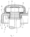
- the end of a fastening part 3 facing a wiper shaft 2 is designated by 1.
- This end 1 is placed on a knurled cone 4 of the wiper shaft 2 and with a Nut 5 secured against unintentional and untimely loosening.
- the end 1 has a back part 6, side cheeks 7 and 8 and a receptacle 9.
- the back part 6, the side cheeks 7 and 8 and the receptacle 9 are formed by deep drawing from a sheet metal part.
- the sheet metal part is first pre-drilled with a hole punch with a small diameter and then the receptacle 9 is drawn downwards.
- the receptacle 9 is then widened to a cone with a cone angle of 15 ° to 20 °, in particular of 18 ° 55 ', and the neck 10 thus formed is compressed, the material being pressed towards the cone tip. This results in a particularly stable bond between the back part 6 and the receptacle 9.
- the outer surface 11 of the receptacle 9 can be made cylindrical. In the drawing, this manufacturing process is shown with a dashed line.
- the first step, the drawing in of the cylindrical neck 10 is shown with long dashed lines, and the neck 10 ′ expanded into a cone is shown with short dashed lines.
- the drawing also clearly shows that the edges 12 and 13 of the side walls 7 and 8 and the receptacle 9 point in the direction of the wiper shaft 2 or in the direction of a windshield or body surface of a motor vehicle, not shown.
- the upper end of the wiper shaft 2 can be covered with the side cheeks 7 and 8, so that the fastening part 3 immediately ends above the body surface.
- This configuration of the fastening part 3 has the advantage that it can be made extremely flat.
- the flat design of the back part 6 has the advantage that the nut 5 can rest on the flat outer surface, for example for a spring ring 14 or a sealing ring, and the fastening part 3 is pressed onto the knurled cone of the wiper shaft 2 without the aid of further components.
- An optimal non-positive and positive connection can be made in that the cone angle of the receptacle 9 is slightly smaller than the knurled cone 4 of the wiper shaft 2, so that the receptacle 9 is slightly expanded when the nut 5 is tightened.
- the inner surface of the receptacle 9, which rests on the cone 4 can be structured so that the knurling digs into the structuring of the receptacle 9.
- the nut 5 can, as shown in the drawing, be designed as a simple nut, but a cap nut can also be used.
- an end cap 15 can be snapped on after tightening, which can be firmly anchored via locking lugs 16 which engage under the nut 5.
Landscapes
- Engineering & Computer Science (AREA)
- Mechanical Engineering (AREA)
- Connection Of Plates (AREA)
- Body Structure For Vehicles (AREA)
- Clamps And Clips (AREA)
- Vehicle Body Suspensions (AREA)
Applications Claiming Priority (3)
| Application Number | Priority Date | Filing Date | Title |
|---|---|---|---|
| DE4230961 | 1992-09-16 | ||
| DE4230961A DE4230961C1 (de) | 1992-09-16 | 1992-09-16 | Wischarm |
| PCT/EP1993/002392 WO1994006654A1 (de) | 1992-09-16 | 1993-09-04 | Wischarm |
Publications (2)
| Publication Number | Publication Date |
|---|---|
| EP0659131A1 EP0659131A1 (de) | 1995-06-28 |
| EP0659131B1 true EP0659131B1 (de) | 1997-01-29 |
Family
ID=6468083
Family Applications (1)
| Application Number | Title | Priority Date | Filing Date |
|---|---|---|---|
| EP93919265A Expired - Lifetime EP0659131B1 (de) | 1992-09-16 | 1993-09-04 | Wischarm |
Country Status (9)
| Country | Link |
|---|---|
| EP (1) | EP0659131B1 (cs) |
| JP (1) | JPH08501511A (cs) |
| BR (1) | BR9307042A (cs) |
| CZ (1) | CZ286504B6 (cs) |
| DE (2) | DE4230961C1 (cs) |
| ES (1) | ES2099469T3 (cs) |
| HU (1) | HU217857B (cs) |
| SK (1) | SK283062B6 (cs) |
| WO (1) | WO1994006654A1 (cs) |
Families Citing this family (3)
| Publication number | Priority date | Publication date | Assignee | Title |
|---|---|---|---|---|
| US5647680A (en) * | 1992-09-16 | 1997-07-15 | Itt Automotive Europe Gmbh | Wiper arm |
| AU2006318319B2 (en) | 2005-11-18 | 2013-01-17 | Glaxo Group Limited | Machine and method for pharmaceutical and pharmaceutical-like product assembly |
| DE102017111591A1 (de) | 2017-05-29 | 2018-11-29 | Valeo Systèmes d'Essuyage | Wischarmkopf für eine Scheibenwischanlage eines Kraftfahrzeugs und Befestigungseinrichtung für einen Wischarmkopf |
Family Cites Families (7)
| Publication number | Priority date | Publication date | Assignee | Title |
|---|---|---|---|---|
| DE2222614A1 (de) * | 1972-05-09 | 1973-11-22 | Bosch Gmbh Robert | Scheibenwischanlage, insbesondere fuer kraftfahrzeuge |
| FR2563482A2 (fr) * | 1982-04-02 | 1985-10-31 | Marchal Equip Auto | Tete d'assemblage matricee d'un element d'essuie-glace, son procede de fabrication et element d'essuie-glace la comportant |
| FR2524407A1 (fr) * | 1982-04-02 | 1983-10-07 | Marchal Equip Auto | Tete d'assemblage matricee d'un element d'essuie-glace, son procede de fabrication et element d'essuie-glace la comportant |
| FR2550110B1 (fr) * | 1983-08-04 | 1985-11-15 | Marchal Equip Auto | Procede de realisation d'un collet double embouti et piece a collet double ainsi obtenue |
| JPS60104438A (ja) * | 1983-08-04 | 1985-06-08 | エキプマン、オ−トモビル、マルシヤル | ワイパ部片の組立てヘツド |
| DE3624270A1 (de) * | 1986-07-18 | 1988-03-10 | Swf Auto Electric Gmbh | Scheibenwischeranlage, insbesondere zur reinigung der windschutzscheibe eines kraftfahrzeuges |
| DE3926714A1 (de) * | 1989-08-12 | 1991-02-14 | Swf Auto Electric Gmbh | Verfahren zur herstellung von insbesondere lackierten metallteilen fuer scheibenwischer und wischarm mit einem insbesondere nach einem solchen verfahren hergestellten metallteil |
-
1992
- 1992-09-16 DE DE4230961A patent/DE4230961C1/de not_active Expired - Fee Related
-
1993
- 1993-09-04 ES ES93919265T patent/ES2099469T3/es not_active Expired - Lifetime
- 1993-09-04 HU HU9500798A patent/HU217857B/hu not_active IP Right Cessation
- 1993-09-04 EP EP93919265A patent/EP0659131B1/de not_active Expired - Lifetime
- 1993-09-04 CZ CZ1995680A patent/CZ286504B6/cs not_active IP Right Cessation
- 1993-09-04 WO PCT/EP1993/002392 patent/WO1994006654A1/de not_active Ceased
- 1993-09-04 BR BR9307042A patent/BR9307042A/pt not_active IP Right Cessation
- 1993-09-04 SK SK348-95A patent/SK283062B6/sk unknown
- 1993-09-04 DE DE59305355T patent/DE59305355D1/de not_active Expired - Lifetime
- 1993-09-04 JP JP6507750A patent/JPH08501511A/ja active Pending
Also Published As
| Publication number | Publication date |
|---|---|
| HU9500798D0 (en) | 1995-05-29 |
| SK34895A3 (en) | 1996-08-07 |
| DE59305355D1 (de) | 1997-03-13 |
| CZ286504B6 (en) | 2000-04-12 |
| WO1994006654A1 (de) | 1994-03-31 |
| EP0659131A1 (de) | 1995-06-28 |
| ES2099469T3 (es) | 1997-05-16 |
| JPH08501511A (ja) | 1996-02-20 |
| SK283062B6 (sk) | 2003-02-04 |
| BR9307042A (pt) | 1999-06-29 |
| DE4230961C1 (de) | 1993-12-02 |
| HU217857B (hu) | 2000-04-28 |
| HUT72195A (en) | 1996-03-28 |
| CZ68095A3 (en) | 1996-01-17 |
Similar Documents
| Publication | Publication Date | Title |
|---|---|---|
| DE10039053A1 (de) | Befestigungsteil für einen Scheibenwischer | |
| EP3889448B1 (de) | Befestigungselement | |
| DE102005044618A1 (de) | Befestigung einer Dachantenne eines Fahrzeuges mit einem Klemmteil | |
| EP0562084B1 (de) | Wischvorrichtung für scheiben von kraftfahrzeugen | |
| EP0659131B1 (de) | Wischarm | |
| EP1137558B1 (de) | Vorrichtung zum befestigen eines wischarms auf einer antriebswelle | |
| DE69314728T2 (de) | Scheibenwischer mit verbessertem Befestigungsteil | |
| DE10210628C1 (de) | Vorrichtung zur spielfreien Ein-Mann Montage eines Anbauteils, oder einer Kfz-Dachantenne | |
| DE19639075B4 (de) | Befestigungseinrichtung für einen Sensor | |
| EP1076621B1 (de) | Vorrichtung zum befestigen eines bauteils auf einer antriebswelle einer wischeranlage | |
| EP0939710A1 (de) | Wischeranlage | |
| DE10122458A1 (de) | Wischerarm, insbesondere für ein Kraftfahrzeug und Verfahren zur Herstellung eines solchen | |
| EP0795443B1 (de) | Einrichtung zur Befestigung | |
| DE10060781A1 (de) | Vorrichtung zum Befestigen von zwei Bauteilen | |
| EP0835792B1 (de) | Wischarm einer Wischvorrichtung für eine Scheibe eines Fahrzeuges | |
| DE3428796A1 (de) | Vorrichtung zur verbindung einer achse und eines werkstuecks, insbesondere eines durch tiefziehen hergestelten werkstuecks, mit hilfe eines spannrings | |
| DE19718749B4 (de) | Umlenkbeschlag für Sicherheitsgurte | |
| DE102004006340A1 (de) | Scheibenwischvorrichtung | |
| DE19939746C2 (de) | Befestigungseinrichtung zur Befestigung von Ultraschallwandlern an Fahrzeugen | |
| EP1323601B1 (de) | Wischarm | |
| DE3029212A1 (de) | Wischvorrichtung fuer scheiben von kraftfahrzeugen | |
| EP0738636A1 (de) | Waschdüse für eine Scheibenwaschanlage eines Fahrzeuges | |
| DE3714701C2 (cs) | ||
| EP3524749B1 (de) | Verbindung von entwässerungskomponenten und rohrstutzen mit einer klemmfeder | |
| DE68903744T2 (de) | Bremsvorrichtung fuer kraftfahrzeug. |
Legal Events
| Date | Code | Title | Description |
|---|---|---|---|
| PUAI | Public reference made under article 153(3) epc to a published international application that has entered the european phase |
Free format text: ORIGINAL CODE: 0009012 |
|
| 17P | Request for examination filed |
Effective date: 19950112 |
|
| AK | Designated contracting states |
Kind code of ref document: A1 Designated state(s): DE ES FR GB IT SE |
|
| 17Q | First examination report despatched |
Effective date: 19951120 |
|
| GRAG | Despatch of communication of intention to grant |
Free format text: ORIGINAL CODE: EPIDOS AGRA |
|
| ITF | It: translation for a ep patent filed | ||
| GRAH | Despatch of communication of intention to grant a patent |
Free format text: ORIGINAL CODE: EPIDOS IGRA |
|
| GRAH | Despatch of communication of intention to grant a patent |
Free format text: ORIGINAL CODE: EPIDOS IGRA |
|
| GRAA | (expected) grant |
Free format text: ORIGINAL CODE: 0009210 |
|
| AK | Designated contracting states |
Kind code of ref document: B1 Designated state(s): DE ES FR GB IT SE |
|
| GBT | Gb: translation of ep patent filed (gb section 77(6)(a)/1977) |
Effective date: 19970210 |
|
| ET | Fr: translation filed | ||
| REF | Corresponds to: |
Ref document number: 59305355 Country of ref document: DE Date of ref document: 19970313 |
|
| REG | Reference to a national code |
Ref country code: ES Ref legal event code: FG2A Ref document number: 2099469 Country of ref document: ES Kind code of ref document: T3 |
|
| PLBE | No opposition filed within time limit |
Free format text: ORIGINAL CODE: 0009261 |
|
| STAA | Information on the status of an ep patent application or granted ep patent |
Free format text: STATUS: NO OPPOSITION FILED WITHIN TIME LIMIT |
|
| 26N | No opposition filed | ||
| REG | Reference to a national code |
Ref country code: GB Ref legal event code: IF02 |
|
| PGFP | Annual fee paid to national office [announced via postgrant information from national office to epo] |
Ref country code: SE Payment date: 20050816 Year of fee payment: 13 |
|
| PG25 | Lapsed in a contracting state [announced via postgrant information from national office to epo] |
Ref country code: SE Free format text: LAPSE BECAUSE OF NON-PAYMENT OF DUE FEES Effective date: 20060905 |
|
| EUG | Se: european patent has lapsed | ||
| PGFP | Annual fee paid to national office [announced via postgrant information from national office to epo] |
Ref country code: ES Payment date: 20070920 Year of fee payment: 15 |
|
| PGFP | Annual fee paid to national office [announced via postgrant information from national office to epo] |
Ref country code: GB Payment date: 20070914 Year of fee payment: 15 |
|
| PGFP | Annual fee paid to national office [announced via postgrant information from national office to epo] |
Ref country code: IT Payment date: 20080918 Year of fee payment: 16 |
|
| GBPC | Gb: european patent ceased through non-payment of renewal fee |
Effective date: 20080904 |
|
| REG | Reference to a national code |
Ref country code: ES Ref legal event code: FD2A Effective date: 20080905 |
|
| PG25 | Lapsed in a contracting state [announced via postgrant information from national office to epo] |
Ref country code: GB Free format text: LAPSE BECAUSE OF NON-PAYMENT OF DUE FEES Effective date: 20080904 |
|
| PG25 | Lapsed in a contracting state [announced via postgrant information from national office to epo] |
Ref country code: ES Free format text: LAPSE BECAUSE OF NON-PAYMENT OF DUE FEES Effective date: 20080905 |
|
| PG25 | Lapsed in a contracting state [announced via postgrant information from national office to epo] |
Ref country code: IT Free format text: LAPSE BECAUSE OF NON-PAYMENT OF DUE FEES Effective date: 20090904 |
|
| PGFP | Annual fee paid to national office [announced via postgrant information from national office to epo] |
Ref country code: DE Payment date: 20120913 Year of fee payment: 20 |
|
| PGFP | Annual fee paid to national office [announced via postgrant information from national office to epo] |
Ref country code: FR Payment date: 20121012 Year of fee payment: 20 |
|
| REG | Reference to a national code |
Ref country code: DE Ref legal event code: R071 Ref document number: 59305355 Country of ref document: DE |
|
| PG25 | Lapsed in a contracting state [announced via postgrant information from national office to epo] |
Ref country code: DE Free format text: LAPSE BECAUSE OF EXPIRATION OF PROTECTION Effective date: 20130905 |