EP3524749B1 - Verbindung von entwässerungskomponenten und rohrstutzen mit einer klemmfeder - Google Patents
Verbindung von entwässerungskomponenten und rohrstutzen mit einer klemmfeder Download PDFInfo
- Publication number
- EP3524749B1 EP3524749B1 EP19152430.5A EP19152430A EP3524749B1 EP 3524749 B1 EP3524749 B1 EP 3524749B1 EP 19152430 A EP19152430 A EP 19152430A EP 3524749 B1 EP3524749 B1 EP 3524749B1
- Authority
- EP
- European Patent Office
- Prior art keywords
- spring
- foot part
- pipe socket
- clamping
- free end
- Prior art date
- Legal status (The legal status is an assumption and is not a legal conclusion. Google has not performed a legal analysis and makes no representation as to the accuracy of the status listed.)
- Active
Links
Images

Classifications
-
- E—FIXED CONSTRUCTIONS
- E04—BUILDING
- E04D—ROOF COVERINGS; SKY-LIGHTS; GUTTERS; ROOF-WORKING TOOLS
- E04D13/00—Special arrangements or devices in connection with roof coverings; Protection against birds; Roof drainage ; Sky-lights
- E04D13/04—Roof drainage; Drainage fittings in flat roofs, balconies or the like
- E04D13/064—Gutters
- E04D13/0645—Connections between gutter and down pipe
-
- F—MECHANICAL ENGINEERING; LIGHTING; HEATING; WEAPONS; BLASTING
- F16—ENGINEERING ELEMENTS AND UNITS; GENERAL MEASURES FOR PRODUCING AND MAINTAINING EFFECTIVE FUNCTIONING OF MACHINES OR INSTALLATIONS; THERMAL INSULATION IN GENERAL
- F16B—DEVICES FOR FASTENING OR SECURING CONSTRUCTIONAL ELEMENTS OR MACHINE PARTS TOGETHER, e.g. NAILS, BOLTS, CIRCLIPS, CLAMPS, CLIPS OR WEDGES; JOINTS OR JOINTING
- F16B2/00—Friction-grip releasable fastenings
- F16B2/20—Clips, i.e. with gripping action effected solely by the inherent resistance to deformation of the material of the fastening
- F16B2/22—Clips, i.e. with gripping action effected solely by the inherent resistance to deformation of the material of the fastening of resilient material, e.g. rubbery material
- F16B2/24—Clips, i.e. with gripping action effected solely by the inherent resistance to deformation of the material of the fastening of resilient material, e.g. rubbery material of metal
- F16B2/241—Clips, i.e. with gripping action effected solely by the inherent resistance to deformation of the material of the fastening of resilient material, e.g. rubbery material of metal of sheet metal
- F16B2/245—Clips, i.e. with gripping action effected solely by the inherent resistance to deformation of the material of the fastening of resilient material, e.g. rubbery material of metal of sheet metal external, i.e. with contracting action
-
- E—FIXED CONSTRUCTIONS
- E04—BUILDING
- E04D—ROOF COVERINGS; SKY-LIGHTS; GUTTERS; ROOF-WORKING TOOLS
- E04D13/00—Special arrangements or devices in connection with roof coverings; Protection against birds; Roof drainage ; Sky-lights
- E04D13/04—Roof drainage; Drainage fittings in flat roofs, balconies or the like
- E04D13/08—Down pipes; Special clamping means therefor
- E04D2013/0846—Interconnecting down pipe parts
Definitions
- the present invention relates to a connection of drainage components, in particular for connecting roof drainage components, for example for connecting a pipe bend or a downpipe to an inlet funnel or water collection box of a roof drainage system. It also relates to a pipe socket with a clamping spring.
- Inlet funnels are usually connected to gutters, which collect rainwater from building roofs and which are attached with gutter brackets along the lower edge of roofs, which collect the water from the gutter and transfer it via at least one intermediate pipe bend or directly to a connected downpipe.
- a water collection box is usually provided, which transfers the water absorbed by the flat roof to a pipe bend or directly to a downpipe.
- Corresponding inlet funnels and water collecting boxes are usually positioned at a great height away from the ground and are difficult to reach. If, for example, the pipe bend or the downpipe detaches from the inlet funnel or water collector due to the force of weight or tension, the effort required to reattach it is sometimes considerable.
- the pipe bends or the downpipes are usually attached separately to the inlet funnels or water collecting tanks in order to avoid unintentional loosening.
- a separate attachment is also possible between pipe bends or a pipe bend and the downpipe or at other positions in the roof drainage system.
- the separate fastening can take place, for example, by screwing, in that the components to be fastened to one another are pushed onto one another and a self-tapping screw is then screwed in from the outside.
- This has the disadvantage that the self-tapping screw damages the usually galvanized drainage component, which can lead to corrosion and undesirable leaks, and the insertion of the screw means additional effort during assembly.
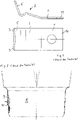
- a spring clamp for connecting a pipe bend or a downpipe with an inlet funnel, as in the figure 1 is shown.
- Such a clamping spring 10 has a foot part 1 which is flat and with which the clamping spring 10 is riveted from the outside onto the pipe socket of the inlet funnel.
- the foot part 1 is followed by a spring part 2, which has the same width as the foot part 1 and which is angled at an obtuse angle relative to the foot part 1, with an end section 5, which carries two claws 3, is angled somewhat more so that the claws 3 claw firmly into the material of the piece of pipe pushed over the pipe socket.
- the inlet funnel In order to be able to slide the piece of pipe over the pipe socket with the spring element riveted on, the inlet funnel has an impression into which the spring element is inserted and which has a contour corresponding to the contour of the spring element, so that the spring element is largely pressed into the impression when the piece of pipe is pushed on can be.
- FIG 2 a cross section through an inlet funnel with a pipe socket 8 is shown, which has an indentation 9 into which a spring element 10 according to the prior art is inserted.
- the present invention is based on the object of specifying a connection of drainage components, in particular roof drainage components, which provides better holding power and does not increase the manufacturing costs of the components or the assembly effort.
- connection with the features of claim 1 and by a pipe socket with the features of claim 9.
- Advantageous and particularly expedient configurations of a connection according to the invention or of a pipe socket according to the invention are specified in the dependent claims.
- connection of drainage components according to the invention in particular roof drainage components, has a clamping spring with a plate-shaped foot part and a spring part adjoining this, the spring part at its end Foot facing away from the free end is provided with at least one claw.
- the clamping spring can claw into a drainage component pushed over it, with the spring force of the clamping spring pressing the claw into the material of the drainage component pushed over.
- the spring part is folded over or bent over at an angle of more than 90° relative to the foot part.
- the clamping spring it can first be produced from a flat sheet metal part, in particular spring steel, for example by stamping, and then a first part is folded over or bent by more than 90° relative to a second part in order to separate the spring part and the train foot part.
- the spring part is also formed by at least two spring tongues arranged next to one another, extending from the base part and being springable independently of one another, each having at least one claw on their free end facing away from the base part.
- the clamping spring offers two independently acting spring tongues which, viewed in the direction from the foot part to the spring part in a width direction that runs perpendicular to the axial direction or direction of the longitudinal axis of the clamping spring from the foot part to the spring part, are positioned next to each other and in particular at a distance from one another.
- connection according to the invention with a clamping spring can be made of a thinner material, for example sheet metal, in particular spring steel, than the previous clamping spring and still has the surprisingly large clamping force.
- the clamping spring can have a thickness of less than 0.5 mm, in particular 0.4 mm or less, at least in the area of the spring part or in the spring part and foot part.
- the edging or bending of the spring part relative to the foot part can preferably take place in the cold state of the clamping spring or of a blank from which the clamping spring is produced.
- the design of the clamping spring allows it to be used in a planar indentation in a pipe socket or even on a surface of a pipe socket without an indentation being necessary at this point.
- the two spring tongues that spring in independently of one another adapt individually to the surface section of the drainage component pushed over them that is opposite them. Due to their comparatively small width, they also better grip curved surface sections.
- the spring part is preferably folded over or bent over by more than 120° or more than 135° in relation to the foot part.
- Each spring tongue is preferably angled, with a web adjoining the foot part and with an end section adjoining the web at the end facing away from the foot part, the end section carrying the at least one claw at its free end and in a direction away from the web from the foot part, is therefore bent outwards in a direction seen from the foot part.
- This fold can also have a radius.
- the web can, for example, be at least essentially parallel to the foot part extend and the end portion may extend at an acute angle to the foot portion.
- the transition from the foot part to the spring part preferably has a radius, so that a bend is preferably provided instead of a "sharp" edge.
- the radius is in particular 1 mm or less.
- the axial ends of the spring tongues facing the foot part coincide with the edge or the beginning of the bend, viewed from the foot part, so that the foot part does not have a slot corresponding to the distance between the spring tongues on its axial end facing the spring part.
- An alternative embodiment provides that the foot part already has a slot at its axial end facing the two spring tongues, i.e. the spring part facing the spring part, corresponding to the slot or the distance between the two spring tongues, according to which the spring tongues extend, so to speak, into the foot part beyond the bend or edging extend into it.
- Each spring tongue preferably has at least two claws at its free end.
- a curved contour, preferably a concave contour, of the free end can be provided between the claws.
- a distance between the spring tongues is preferably 1/4 or 1/3 of the width of each spring tongue.
- the spring tongues have, in particular, identical widths and can otherwise be designed identically to one another.
- the foot part has at least one bore for a rivet or a screw.
- the length of the clamping spring before folding or bending is 25 to 40 mm, preferably between 30 and 35 mm.
- the clamping spring can have a length of less than 25 mm when viewed from above.
- the spring tongues can have a length of 10 to 20 mm, for example 14 to 17 mm, in particular 15 mm, in particular before being folded over or bent over. If the bending or edging is carried out exclusively in the area of the spring tongues, these can accordingly have a comparatively shorter axial length after being bent or edged, with which they are positioned above the foot part.
- each spring tongue preferably has a length which is a multiple of the length of the angled end section, for example three times, four times or more.
- a pipe socket according to the invention has a clamping spring of the type shown, the clamping spring being fastened to an outer or inner surface of the pipe socket, preferably to an outer surface of the pipe socket, and the folded edge or bend between the foot part and the spring part facing a free end of the pipe socket is.
- the pipe socket preferably has an indentation into which the foot part of the clamping spring is inserted, the indentation being flat.
- Such a pipe socket can, for example, be part of an inlet funnel or water collection box, to which a pipe bend or downpipe is connected by means of the pipe socket.
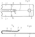
- FIG 3 an example of a stamped sheet metal part for the production of a clamping spring according to the invention is shown, which still has a flat shape.
- the clamping spring 10 according to the figure 4 produced by bending the spring part 2 in relation to the foot part 1.
- the foot part 1 still has a flat shape.
- a bore 6 introduced for inserting a rivet or a screw to attach the clamping spring 10, for example, to a pipe socket.
- the spring part 2 has two spring tongues 2.1, 2.2 that can be compressed individually, each carrying two claws 3 on their free end facing away from the foot part 1.
- the spring part 2 or the spring tongues 2.1, 2.2 are bent at an angle of at least approximately 180° relative to the foot part 1, so that a web 4, which adjoins the foot part 1 behind the bend, is positioned essentially parallel to the foot part 1, whereas an end section 5 runs at an acute angle to the foot part 1 at the end of the web 4 facing away from the foot part 1 .
- This end section 5 carries the claws 3 at its free end.
- the claws 3 engage in the material of a drainage component 11 pushed onto the pipe socket 8 on which the spring element 10 is mounted, see in particular FIG figure 6 .
- the foot part 1 is inserted into an indentation 9 of the pipe socket 8, the indentation 9, as can be seen from FIG figure 6 can recognize, in contrast to the design according to the figure 2 , just can be executed.
- the foot part 1 is fastened in the impression 9 by means of the rivet 7 .
- the two spring tongues 2.1, 2.2 have a distance D in the width direction of the clamping spring 10, which extends perpendicularly to the longitudinal axis 12 shown here, which is, for example, at least 1/4 or 1/3 of the width B of each spring tongue 2.1, 2.2.
Landscapes
- Engineering & Computer Science (AREA)
- General Engineering & Computer Science (AREA)
- Mechanical Engineering (AREA)
- Architecture (AREA)
- Civil Engineering (AREA)
- Structural Engineering (AREA)
- Clamps And Clips (AREA)
Description
- Die vorliegende Erfindung betrifft eine Verbindung von Entwässerungskomponenten, insbesondere zur Verbindung von Dachentwässerungskomponenten, beispielsweise zum Anschluss eines Rohrbogens oder eines Fallrohrs an einen Einlauftrichter oder Wasserfangkasten eines Dachentwässerungssystems. Sie betrifft auch einen Rohrstutzen mit einer Klemmfeder.
- An Dachrinnen, welche Regenwasser von Gebäudedächern aufnehmen und die entsprechend mit Rinnenhaltern entlang des unteren Randes von Dächern befestigt werden, werden in der Regel Einlauftrichter angeschlossen, die das Wasser aus der Dachrinne sammeln und über wenigstens einen zwischengeschalteten Rohrbogen oder unmittelbar an ein angeschlossenes Fallrohr übergeben. Bei Flachdächern ist in der Regel ein Wasserfangkasten vorgesehen, der das vom Flachdach aufgenommene Wasser entsprechend an einen Rohrbogen oder direkt an ein Fallrohr übergibt. Entsprechende Einlauftrichter und Wasserfangkästen sind in der Regel nur schwer erreichbar in einer großen Höhe entfernt vom Erdboden positioniert. Wenn sich beispielsweise durch die Gewichtskraft oder durch Spannungen der Rohrbogen oder das Fallrohr vom Einlauftrichter oder Wasserfangkasten löst, ist der Aufwand einer erneuten Befestigung mitunter erheblich. Daher werden die Rohrbögen oder die Fallrohre in der Regel gesondert an den Einlauftrichtern oder Wasserfangkästen befestigt, um ein unbeabsichtigtes Lösen zu vermeiden. Selbstverständlich ist eine solche gesonderte Befestigung auch zwischen Rohrbögen oder einem Rohrbogen und dem Fallrohr oder an anderen Positionen im Dachentwässerungssystem möglich.
- Die gesonderte Befestigung kann beispielsweise durch Verschrauben erfolgen, indem die miteinander zu befestigenden Komponenten aufeinander geschoben werden und anschließend von außen eine Blechschraube eingedreht wird. Dies hat den Nachteil, dass die Blechschraube die in der Regel verzinkte Entwässerungskomponente beschädigt, was zu Korrosion und einer unerwünschten Undichtigkeit führen kann, und zudem das Einbringen der Schraube einen zusätzlichen Aufwand bei der Montage bedeutet. Es wurde daher bereits eine Klemmfeder zur Verbindung eines Rohrbogens oder eines Fallrohres mit einem Einlauftrichter vorgeschlagen, wie sie in der
Figur 1 dargestellt ist. Eine solche Klemmfeder 10 weist einen Fußteil 1 auf, der eben ist und mit welchem die Klemmfeder 10 von außen auf dem Rohrstutzen des Einlauftrichters angenietet wird. An den Fußteil 1 schließt sich ein Federteil 2 an, der dieselbe Breite wie der Fußteil 1 aufweist und der mit einem stumpfen Winkel gegenüber dem Fußteil 1 abgewinkelt ist, wobei ein Endabschnitt 5, der zwei Krallen 3 trägt, etwas stärker abgewinkelt ist, damit sich die Krallen 3 fest in das Material des über den Rohrstutzen geschobenen Rohrstückes krallen. - Um das Rohrstück über den Rohrstutzen mit dem angenieteten Federelement aufschieben zu können, weist der Einlauftrichter eine Einprägung auf, in die das Federelement eingesetzt ist und die eine Kontur entsprechend der Kontur des Federelementes aufweist, sodass das Federelement beim Aufschieben des Rohrstückes weitgehend in die Einprägung eingedrückt werden kann. Zur Verdeutlichung ist in der
Figur 2 ein Querschnitt durch einen Einlauftrichter mit einem Rohrstutzen 8 dargestellt, welcher eine Einprägung 9 aufweist, in die ein Federelement 10 gemäß dem Stand der Technik eingesetzt ist. - In der Praxis hat sich nun herausgestellt, dass Situationen auftreten können, insbesondere wenn die Verbindung der Entwässerungskomponenten einer unmittelbaren starken Sonnenstrahlung ausgesetzt ist, bei welchen die Klemmkraft zwischen den Entwässerungskomponenten verstärkt werden sollte, um ein unbeabsichtigtes Lösen der Komponenten voneinander sicher zu vermeiden. Prinzipiell kann dies durch Einsetzen mehrerer Klemmfedern in mehrere Einprägungen im Rohrstutzen geschehen, wodurch annähernd die doppelte Klemmkraft erreicht werden kann, wenn zwei Klemmfedern vorgesehen sind, im Vergleich zum Vorsehen einer einzigen Klemmfeder. Jedoch erhöht die Anzahl der Klemmfedern auch die Herstellungskosten der entsprechenden Entwässerungskomponente, die mit den Klemmfedern versehen ist.
- Andere Lösungen sehen vor, nicht nur die Entwässerungskomponente, welche die Klemmfeder trägt, sondern auch die Gegenkomponente, beispielsweise das Fallrohr oder den Rohrstutzen, mit einer Einprägung zu versehen, in welche eine Klemmfeder formschlüssig einrasten kann. Auch diese Lösung ist mit einem erhöhten Aufwand und damit erhöhten Kosten bei der Herstellung der Komponenten verbunden. Zudem wird die Montage verkompliziert, da sichergestellt werden muss, dass die Klemmfeder ausreichend in die Einprägung der Gegenkomponente einrastet und hierfür die beiden Komponenten geeignet zueinander in der Umfangsrichtung ausgerichtet werden.
- Aus
DE 101 60 194 A1 sind eine Verbindung von Entwässerungskomponente mit einer Klemmfeder und ein Rohrstutzen mit einer Klemmfeder bekannt. - Der vorliegenden Erfindung liegt die Aufgabe zugrunde, eine Verbindung von Entwässerungskomponenten, insbesondere Dachentwässerungskomponenten, anzugeben, die eine bessere Haltekraft zur Verfügung stellt und die Herstellungskosten der Komponenten sowie den Montageaufwand nicht erhöht.
- Die erfindungsgemäße Aufgabe wird durch eine Verbindung mit den Merkmalen von Anspruch 1 und durch einen Rohrstutzen mit dem Merkmalen von Anspruch 9 gelöst. In den abhängigen Ansprüchen werden vorteilhafte und besonders zweckmäßige Ausgestaltungen einer erfindungsgemäßen Verbindung, bzw. eines erfindungsgemäßen Rohrstutzens, angegeben.
- Die erfindungsgemäße Verbindung von Entwässerungskomponenten, insbesondere von Dachentwässerungskomponenten, weist eine Klemmfeder mit einem plattenförmigen Fußteil und einem sich an diesen anschließenden Federteil auf, wobei der Federteil an seinem vom Fußteil abgewandten freien Ende mit wenigstens einer Kralle versehen ist. Mit dieser Kralle kann sich die Klemmfeder in eine über sie geschobene Entwässerungskomponente einkrallen, wobei die Federkraft der Klemmfeder die Kralle in das Material der übergeschobenen Entwässerungskomponente eindrückt.
- Erfindungsgemäß ist der Federteil mit einem Winkel von mehr als 90° gegenüber dem Fußteil umgekantet oder umgebogen. Das bedeutet, bei der Herstellung der Klemmfeder kann diese zunächst aus einem ebenen Blechteil, insbesondere Federstahl, hergestellt werden, beispielsweise durch Stanzen, und anschließend wird ein erster Teil gegenüber einem zweiten Teil um mehr als 90° umgekantet oder umgebogen, um den Federteil und den Fußteil auszubilden.
- Erfindungsgemäß wird der Federteil ferner durch wenigstens zwei nebeneinander angeordnete, sich vom Fußteil aus erstreckende, unabhängig voneinander einfederbare Federzungen gebildet, die an ihrem vom Fußteil abgewandten freien Ende jeweils wenigstens eine Kralle aufweisen. Demgemäß bietet die Klemmfeder zwei unabhängig voneinander wirkende Federzungen, die, betrachtet in Richtung vom Fußteil zum Federteil in einer Breitenrichtung, die senkrecht zur Axialrichtung oder Richtung der Längsachse der Klemmfeder vom Fußteil zum Federteil verläuft, nebeneinander und insbesondere mit einem Abstand zueinander positioniert sind.
- Durch diese Gestaltung der Klemmfeder kann eine mehr als doppelt so große Haltekraft zwischen den Entwässerungskomponenten im Vergleich zur eingangs beschriebenen in den
Figuren 1 und 2 dargestellten Klemmfeder erreicht werden. Somit kann eine erfindungsgemäße Verbindung mit einer einzigen Klemmfeder eine größere Haltekraft gewährleisten, als bisher zwei separat zueinander vorgesehene Klemmfedern an ein und demselben Rohrstutzen. Dabei reduziert das Vorsehen nur einer einzigen Klemmfeder die Herstellungskosten gegenüber dem Vorsehen von zwei separaten Klemmfedern. - Insbesondere kann die erfindungsgemäße Verbindung mit einer Klemmfeder aus einem dünneren Material, beispielsweise Blech, insbesondere Federstahl, hergestellt werden, als die bisherige Klemmfeder und weist dennoch die überraschend große Klemmkraft auf. So kann die Klemmfeder beispielsweise zumindest im Bereich des Federteils oder im Federteil und Fußteil eine Stärke von weniger als 0,5 mm, insbesondere von 0,4 mm oder weniger aufweisen.
- Das Umkanten oder Umbiegen des Federteils gegenüber dem Fußteil kann bevorzugt im kalten Zustand der Klemmfeder beziehungsweise eines Rohteils, aus dem die Klemmfeder hergestellt wird, erfolgen.
- Die Gestaltung der Klemmfeder ermöglicht deren Einsatz in einer ebenen Einprägung in einem Rohrstutzen oder sogar auf einer Oberfläche eines Rohrstutzens, ohne dass an dieser Stelle eine Einprägung notwendig ist.
- Die beiden unabhängig voneinander einfedernden Federzungen passen sich individuell an den ihnen jeweils gegenüberstehen Oberflächenabschnitt der übergeschobenen Entwässerungskomponente an. Durch ihre vergleichsweise geringe Breite greifen sie zudem besser in gekrümmte Oberflächenabschnitte ein.
- Bevorzugt ist der Federteil um mehr als 120° oder mehr als 135° gegenüber dem Fußteil umgekantet oder umgebogen.
- Jede Federzunge ist bevorzugt winklig ausgeführt, mit einem sich an den Fußteil anschließenden Steg und mit einem sich an den Steg an dem vom Fußteil abgewandten Ende anschließenden Endabschnitt, wobei der Endabschnitt an seinem freien Ende die wenigstens eine Kralle trägt und vom Steg in einer Richtung weg vom Fußteil, demnach in einer Richtung vom Fußteil gesehen nach außen abgekantet ist. Auch diese Abkantung kann einen Radius aufweisen. Der Steg kann sich beispielsweise zumindest im Wesentlichen parallel zum Fußteil erstrecken und der Endabschnitt kann sich mit einem spitzen Winkel zum Fußteil erstrecken.
- Der Übergang vom Fußteil zum Federteil weist bevorzugt einen Radius auf, sodass demnach bevorzugt eine Umbiegung anstelle einer "scharfen" Umkantung vorgesehen ist. Der Radius beträgt insbesondere 1 mm oder weniger.
- Gemäß einer Ausführungsform der Erfindung fallen die dem Fußteil zugewandten axialen Enden der Federzungen mit der Umkantung beziehungsweise dem Beginn der Umbiegung, betrachtet vom Fußteil aus, zusammen, sodass der Fußteil keinen dem Abstand zwischen den Federzungen entsprechenden Schlitz an seinem dem Federteil zugewandten axialen Ende aufweist. Eine alternative Ausführungsform sieht vor, dass der Fußteil an seinem den beiden Federzungen, das heißt dem Federteil zugewandten axialen Ende, bereits einen Schlitz entsprechend dem Schlitz oder dem Abstand zwischen den beiden Federzungen aufweist, demnach sich die Federzungen sozusagen bis in den Fußteil jenseits der Umbiegung oder Umkantung hinein erstrecken.
- Bevorzugt weist jede Federzunge an ihrem freien Ende wenigstens zwei Krallen auf. Zwischen den Krallen kann insbesondere eine bogenförmige Kontur, bevorzugt konkave Kontur, des freien Endes vorgesehen sein.
- Ein Abstand zwischen den Federzungen beträgt bevorzugt 1/4 oder 1/3 der Breite jeder Federzunge.
- Die Federzungen weisen insbesondere identische Breiten auf und können auch im Übrigen identisch zueinander gestaltet sein.
- Der Fußteil weist insbesondere wenigstens eine Bohrung für einen Niet oder eine Schraube auf.
- Beispielsweise beträgt die Länge der Klemmfeder vor dem Umkanten oder Umbiegen 25 bis 40 mm, bevorzugt zwischen 30 und 35 mm. Nach dem Umbiegen oder Umkanten kann die Klemmfeder eine Länge von weniger als 25 mm aufweisen, in einer Draufsicht betrachtet.
- Die Federzungen können insbesondere vor dem Umkanten oder Umbiegen eine Länge von 10 bis 20 mm aufweisen, beispielsweise von 14 bis 17 mm, insbesondere 15 mm. Wenn die Umbiegung oder Umkantung ausschließlich im Bereich der Federzungen durchgeführt wird, können diese entsprechend nach ihrem Umbiegen oder Umkantung eine vergleichsweise kürzere axiale Länge aufweisen, mit welcher sie oberhalb des Fußteils positioniert sind.
- Der Steg einer jeden Federzunge weist vorzugsweise eine Länge auf, die ein Vielfaches der Länge des abgewinkelten Endabschnitts beträgt, beispielsweise das Dreifache, Vierfache oder mehr.
- Ein erfindungsgemäßer Rohrstutzen weist eine Klemmfeder der dargestellten Art auf, wobei die Klemmfeder an einer äußeren oder inneren Oberfläche des Rohrstutzens, bevorzugt an einer äußeren Oberfläche des Rohrstutzens, befestigt ist und die Umkantung oder Umbiegung zwischen dem Fußteil und dem Federteil einem freien Ende des Rohrstutzens zugewandt ist. Das bedeutet, beim Aufschieben einer zweiten rohrförmigen Komponente auf den Rohrstutzen wird die zweite Komponente zunächst über die Umkantung oder Umbiegung hinweg geschoben, bevor sie in Kontakt mit den Krallen an den freien Enden der Federzungen gelangt.
- Bevorzugt weist der Rohrstutzen eine Einprägung auf, in welche der Fußteil der Klemmfeder eingesetzt ist, wobei die Einprägung eben ausgeführt ist.
- Ein solcher Rohrstutzen kann beispielsweise Bestandteil eines Einlauftrichters oder Wasserfangkastens sein, an welchen mittels des Rohrstutzens ein Rohrbogen oder Fallrohr angeschlossen wird.
- Die Erfindung soll nachfolgend anhand eines Ausführungsbeispiels und den Figuren exemplarisch beschrieben werden.
- Es zeigen:
- Figur 1
- eine Klemmfeder gemäß dem Stand der Technik in einer Seitenansicht und einer Draufsicht;
- Figur 2
- einen schematischen Querschnitt durch eine am Rohrstutzen eines Einlauftrichters montierte Klemmfeder gemäß dem Stand der Technik;
- Figur 3
- ein Rohteil zur Herstellung einer Klemmfeder vor dem Umbiegen des Federteils;
- Figur 4
- eine erfindungsgemäße Verbindung in einer Seitenansicht;
- Figur 5
- einen erfindungsgemäßen Rohrstutzen mit Klemmfeder;
- Figur 6
- einen Querschnitt durch den Rohrstutzen der
Figur 5 . - In der
Figur 3 ist ein beispielsweise ausgestanztes Blechteil zur Herstellung einer erfindungsgemäßen Klemmfeder gezeigt, welches eine noch ebene Form aufweist. Aus diesem Rohteil wird die Klemmfeder 10 gemäß derFigur 4 durch Umbiegen des Federteils 2 gegenüber dem Fußteil 1 hergestellt. Der Fußteil 1 weist auch nach dem Umbiegen des Federteils 2 noch eine ebene Form auf. Im gezeigten Ausführungsbeispiel ist in den Fußteil 1 eine Bohrung 6 zum Einbringen eines Niet oder einer Schraube eingebracht, um die Klemmfeder 10 beispielsweise an einem Rohrstutzen zu befestigen. - Wie man auch aus der
Figur 5 erkennen kann, weist der Federteil 2 zwei einzeln einfederbare Federzungen 2.1, 2.2 auf, die an ihrem freien vom Fußteil 1 abgewandten Ende jeweils zwei Krallen 3 tragen. Der Federteil 2 beziehungsweise die Federzungen 2.1, 2.2 sind mit einem Winkel von wenigstens annähernd 180° gegenüber dem Fußteil 1 umgebogen, sodass ein Steg 4, der sich hinter der Umbiegung an den Fußteil 1 anschließt, im Wesentlichen parallel zum Fußteil 1 positioniert ist, wohingegen ein Endabschnitt 5 an dem dem Fußteil 1 abgewandten Ende des Stegs 4 in einem spitzen Winkel zum Fußteil 1 verläuft. Dieser Endabschnitt 5 trägt an seinem freien Ende die Krallen 3. - Die Krallen 3 greifen in das Material einer auf den Rohrstutzen 8, an welchem das Federelement 10 montiert ist, aufgeschobenen Entwässerungskomponente 11 ein, siehe besonders die
Figur 6 . - Der Fußteil 1 ist in eine Einprägung 9 des Rohrstutzens 8 eingesetzt, wobei die Einprägung 9, wie man aus der
Figur 6 erkennen kann, im Unterschied zur Gestaltung gemäß derFigur 2 , eben ausgeführt sein kann. Beispielsweise ist der Fußteil 1 mittels des Niet 7 in der Einprägung 9 befestigt. - Die beiden Federzungen 2.1, 2.2 weisen in der Breitenrichtung der Klemmfeder 10, die sich senkrecht zur hier dargestellten Längsachse 12 erstreckt, einen Abstand D auf, der beispielsweise wenigstens 1/4 oder 1/3 der Breite B jeder Federzunge 2.1, 2.2 beträgt.
-
- 1
- Fußteil
- 2
- Federteil
- 2.1,2.2
- Federzunge
- 3
- Kralle
- 4
- Steg
- 5
- Endabschnitt
- 6
- Bohrung
- 7
- Niet
- 8
- Rohrstutzen
- 9
- Einprägung
- 10
- Klemmfeder
- 11
- Entwässerungskomponente
- 12
- Längsachse
- D
- Abstand
- B
- Breite
Claims (11)
- Verbindung von Entwässerungskomponenten (8, 11) mit einer ersten Entwässerungskomponente (8), an deren Oberfläche eine Klemmfeder (10) befestigt ist, und einer zweiten Entwässerungskomponente (11), die über die Klemmfeder (10) geschoben ist, wobei die Klemmfeder (10) einen plattenförmigen Fußteil (1) und einen sich an diesem anschließenden Federteil (2) aufweist; wobeider Federteil (2) an seinem vom Fußteil (1) abgewandten freien Ende wenigstens eine Kralle (3) aufweist; wobeieine Federkraft der Klemmfeder (10) die wenigstens eine Kralle (3) in das Material der übergeschobenen Entwässerungskomponente (11) eindrückt; dadurch gekennzeichnet, dassder Federteil (2) mit einem Winkel von mehr als 90° gegenüber dem Fußteil (1) umgekantet oder umgebogen ist und durch wenigstens zwei nebeneinander angeordnete, sich vom Fußteil (1) aus erstreckende, unabhängig voneinander einfederbare Federzungen (2.1, 2.2) gebildet wird, die an ihrem vom Fußteil (1) abgewandten freien Ende jeweils wenigstens eine Kralle (3) aufweisen.
- Verbindung gemäß Anspruch 1, dadurch gekennzeichnet, dass der Federteil (2) um mehr als 120° oder 135° gegenüber dem Fußteil (1) umgekantet oder umgebogen ist.
- Verbindung gemäß einem der Ansprüche 1 oder 2, dadurch gekennzeichnet, dass jede Federzunge (2.1, 2.2) winklig ausgeführt ist, mit einem sich an den Fußteil (1) anschließenden Steg (4) und einem sich an den Steg (4) an dem vom Fußteil (1) abgewandten Ende anschließenden Endabschnitt (5), der an seinem freien Ende die wenigstens eine Kralle (3) trägt und vom Steg (4) in eine Richtung weg vom Fußteil (1) abgekantet ist.
- Verbindung gemäß Anspruch 3, dadurch gekennzeichnet, dass sich der Steg (4) zumindest im Wesentlichen parallel zum Fußteil (1) erstreckt und sich der Endabschnitt (5) mit einem spitzen Winkel zum Fußteil (1) erstreckt.
- Verbindung gemäß einem der Ansprüche 1 bis 4, dadurch gekennzeichnet, dass die Federzungen (2.1, 2.2) an ihrem freien Ende jeweils wenigstens zwei Krallen (3) aufweisen.
- Verbindung gemäß einem der Ansprüche 1 bis 5, dadurch gekennzeichnet, dass sich die Federzungen (2.1, 2.2) mit einem Abstand (D) parallel zueinander erstrecken.
- Verbindung gemäß Anspruch 6, dadurch gekennzeichnet, dass der Abstand (D) wenigstens 1/4 oder 1/3 einer Breite (B) jeder Federzunge (2.1, 2.2) beträgt.
- Verbindung gemäß einem der Ansprüche 1 bis 7, dadurch gekennzeichnet, dass der Fußteil (1) eine Bohrung (6) für einen Niet (7) oder eine Schraube umfasst.
- Rohrstutzen (8) mit einer Klemmfeder (10), wobei die Klemmfeder (10) einen plattenförmigen Fußteil (1) und einen sich an diesem anschließenden Federteil (2) aufweist; wobeider Federteil (2) an seinem vom Fußteil (1) abgewandten freien Ende wenigstens eine Kralle (3) zum Eindrücken in das Material einer übergeschobenen Entwässerungskomponente (11) aufweist;dadurch gekennzeichnet, dassder Federteil (2) mit einem Winkel von mehr als 90° gegenüber dem Fußteil (1) umgekantet oder umgebogen ist und durch wenigstens zwei nebeneinander angeordnete, sich vom Fußteil (1) aus erstreckende, unabhängig voneinander einfederbare Federzungen (2.1, 2.2) gebildet wird, die an ihrem vom Fußteil (1) abgewandten freien Ende jeweils wenigstens eine Kralle (3) aufweisen und dass die Klemmfeder (10) an einer äußeren oder inneren Oberfläche des Rohrstutzens (8) befestigt ist und die Umkantung oder Umbiegung zwischen dem Fußteil (1) und dem Federteil (2) einem freien Ende des Rohrstutzens (8) zugewandt ist.
- Rohrstutzen (8) gemäß Anspruch 9, dadurch gekennzeichnet, dass der Rohrstutzen (8) eine Einprägung (9) aufweist, in welche der Fußteil (1) der Klemmfeder (10) eingesetzt ist, wobei die Einprägung (9) eben ausgeführt ist.
- Einlauftrichter oder Wasserfangkasten mit einem Rohrstutzen (8) gemäß einem der Ansprüche 9 oder 10 zum Anschluss eines Rohrbogens oder eines Fallrohres.
Applications Claiming Priority (1)
| Application Number | Priority Date | Filing Date | Title |
|---|---|---|---|
| DE102018202029.9A DE102018202029A1 (de) | 2018-02-09 | 2018-02-09 | Klemmfeder zur Verbindung von Entwässerungskomponenten, insbesondere Dachentwässerungskomponenten |
Publications (2)
| Publication Number | Publication Date |
|---|---|
| EP3524749A1 EP3524749A1 (de) | 2019-08-14 |
| EP3524749B1 true EP3524749B1 (de) | 2022-11-30 |
Family
ID=65041590
Family Applications (1)
| Application Number | Title | Priority Date | Filing Date |
|---|---|---|---|
| EP19152430.5A Active EP3524749B1 (de) | 2018-02-09 | 2019-01-18 | Verbindung von entwässerungskomponenten und rohrstutzen mit einer klemmfeder |
Country Status (5)
| Country | Link |
|---|---|
| EP (1) | EP3524749B1 (de) |
| DE (1) | DE102018202029A1 (de) |
| DK (1) | DK3524749T3 (de) |
| HU (1) | HUE060488T2 (de) |
| PL (1) | PL3524749T3 (de) |
Citations (1)
| Publication number | Priority date | Publication date | Assignee | Title |
|---|---|---|---|---|
| EP1722145B1 (de) * | 2005-05-13 | 2011-01-05 | Metallwarenfabrik Marktoberdorf GmbH & Co. KG | Rohrelement mit Schutzelement |
Family Cites Families (11)
| Publication number | Priority date | Publication date | Assignee | Title |
|---|---|---|---|---|
| US357893A (en) * | 1887-02-15 | Printer s copy-holder | ||
| US2478100A (en) * | 1947-10-29 | 1949-08-02 | Harry H Histand | Rain water conductor bracket |
| US2810173A (en) * | 1954-03-12 | 1957-10-22 | Joseph M Bearden | Gutter screen clip |
| GB1168788A (en) * | 1965-10-15 | 1969-10-29 | Reginald Leslie Adams | A new or improved Spring Clip |
| ZA765771B (en) * | 1976-09-30 | 1977-08-31 | Metal Box Co Ltd | Containers |
| JP3108030B2 (ja) * | 1997-03-13 | 2000-11-13 | 東京フォーミング株式会社 | 配管の抜け止め装置 |
| DE10110123A1 (de) * | 2001-03-02 | 2002-09-05 | Hilti Ag | Befestigungselement für längliche Gegenstände |
| DE10160194A1 (de) * | 2001-12-09 | 2003-06-18 | Zambelli Fertigungs Gmbh | Montagehilfe für Regenwasser-Ablaufgarnituren |
| DE10353660A1 (de) * | 2003-11-17 | 2005-06-23 | Rösle Metallwarenfabrik GmbH & Co. KG | Leitungssystem zum Ableiten von Flüssigkeit |
| US7658036B2 (en) * | 2003-12-24 | 2010-02-09 | Premier Gutter Cover Llc | Self-cleaning gutter cover |
| TWI566345B (zh) * | 2014-09-05 | 2017-01-11 | 台達電子工業股份有限公司 | 用於夾持電子元件的夾具 |
-
2018
- 2018-02-09 DE DE102018202029.9A patent/DE102018202029A1/de not_active Withdrawn
-
2019
- 2019-01-18 DK DK19152430.5T patent/DK3524749T3/da active
- 2019-01-18 EP EP19152430.5A patent/EP3524749B1/de active Active
- 2019-01-18 HU HUE19152430A patent/HUE060488T2/hu unknown
- 2019-01-18 PL PL19152430.5T patent/PL3524749T3/pl unknown
Patent Citations (1)
| Publication number | Priority date | Publication date | Assignee | Title |
|---|---|---|---|---|
| EP1722145B1 (de) * | 2005-05-13 | 2011-01-05 | Metallwarenfabrik Marktoberdorf GmbH & Co. KG | Rohrelement mit Schutzelement |
Also Published As
| Publication number | Publication date |
|---|---|
| HUE060488T2 (hu) | 2023-03-28 |
| DE102018202029A1 (de) | 2019-08-14 |
| DK3524749T3 (da) | 2022-12-12 |
| PL3524749T3 (pl) | 2023-02-27 |
| EP3524749A1 (de) | 2019-08-14 |
Similar Documents
| Publication | Publication Date | Title |
|---|---|---|
| DE202018107451U1 (de) | Abdeckvorrichtung und Abdeckplatte | |
| DE102011050856A1 (de) | System zum Befestigen von Solarmodulen | |
| WO2020084143A1 (de) | Verkleidungssystem für eine wand, anordnung des verkleidungssystems und verfahren zur montage des verkleidungssystems | |
| DE69905780T2 (de) | Befestigungsschelle von Rohren und Verfahren zur Herstellung | |
| DE69627022T2 (de) | Ein Element zur Verbindung an einer Dachrinne oder Ähnlichem und ein Verfahren zur Herstellung eines solchen Elements | |
| DE102010005194A1 (de) | Verbindungsvorrichtung für Bauteile | |
| EP2234199A1 (de) | Antennenanordnung mit einer Spreizbefestigung | |
| DE8230187U1 (de) | Kotfluegel in blechkonstruktionsbauweise fuer insbesondere lastkraftfahrzeuge | |
| EP3524749A1 (de) | Klemmfeder zur verbindung von entwässerungskomponenten, insbesondere dachentwässerungskomponenten | |
| DE102012108699B4 (de) | Schottplattenelement und System aus einem Schottplattenelement und einem Hohlprofilträger | |
| EP0327827B1 (de) | Stumpfgeschweisstes Metallrohr mit Muffe, insbesondere Regenfallrohr | |
| EP4170105B1 (de) | Fassadenpaneel | |
| EP0761900B1 (de) | Dachpfannensicherung | |
| DE1575159A1 (de) | Spannschelle fuer rohrfoermige Koerper | |
| EP1902857B1 (de) | Rinne zum Binden von Papierbogen | |
| DE10003950C1 (de) | Vorrichtung zur Verhinderung des Abrutschens von Eis und Schnee von Dächern | |
| AT508615A2 (de) | Schneefanghaken | |
| DE102017219810A1 (de) | Bauteilverbund | |
| EP1860252B1 (de) | Traufenlüftungselement mit umbiegbarem Abstandhalter | |
| DE102006012634B4 (de) | Führungsschiene für einen Seilzugfensterheber | |
| DE29911199U1 (de) | Rohrschelle | |
| DE202020105989U1 (de) | Befestigungskonsole, Vorrichtung zur Flächenbegrenzung | |
| DE202022104730U1 (de) | Falzklemme für Blitzschutz-Anlagen | |
| DE102008064302B4 (de) | Fenster | |
| DE102009015670B4 (de) | Kraftfahrzeug mit einem Motorlängsträger |
Legal Events
| Date | Code | Title | Description |
|---|---|---|---|
| PUAI | Public reference made under article 153(3) epc to a published international application that has entered the european phase |
Free format text: ORIGINAL CODE: 0009012 |
|
| STAA | Information on the status of an ep patent application or granted ep patent |
Free format text: STATUS: THE APPLICATION HAS BEEN PUBLISHED |
|
| AK | Designated contracting states |
Kind code of ref document: A1 Designated state(s): AL AT BE BG CH CY CZ DE DK EE ES FI FR GB GR HR HU IE IS IT LI LT LU LV MC MK MT NL NO PL PT RO RS SE SI SK SM TR |
|
| AX | Request for extension of the european patent |
Extension state: BA ME |
|
| STAA | Information on the status of an ep patent application or granted ep patent |
Free format text: STATUS: REQUEST FOR EXAMINATION WAS MADE |
|
| 17P | Request for examination filed |
Effective date: 20200124 |
|
| RBV | Designated contracting states (corrected) |
Designated state(s): AL AT BE BG CH CY CZ DE DK EE ES FI FR GB GR HR HU IE IS IT LI LT LU LV MC MK MT NL NO PL PT RO RS SE SI SK SM TR |
|
| RAP1 | Party data changed (applicant data changed or rights of an application transferred) |
Owner name: ROESLE GROUP GMBH |
|
| GRAP | Despatch of communication of intention to grant a patent |
Free format text: ORIGINAL CODE: EPIDOSNIGR1 |
|
| STAA | Information on the status of an ep patent application or granted ep patent |
Free format text: STATUS: GRANT OF PATENT IS INTENDED |
|
| INTG | Intention to grant announced |
Effective date: 20220628 |
|
| GRAS | Grant fee paid |
Free format text: ORIGINAL CODE: EPIDOSNIGR3 |
|
| GRAA | (expected) grant |
Free format text: ORIGINAL CODE: 0009210 |
|
| STAA | Information on the status of an ep patent application or granted ep patent |
Free format text: STATUS: THE PATENT HAS BEEN GRANTED |
|
| AK | Designated contracting states |
Kind code of ref document: B1 Designated state(s): AL AT BE BG CH CY CZ DE DK EE ES FI FR GB GR HR HU IE IS IT LI LT LU LV MC MK MT NL NO PL PT RO RS SE SI SK SM TR |
|
| REG | Reference to a national code |
Ref country code: CH Ref legal event code: EP Ref country code: GB Ref legal event code: FG4D Free format text: NOT ENGLISH |
|
| REG | Reference to a national code |
Ref country code: DK Ref legal event code: T3 Effective date: 20221208 |
|
| REG | Reference to a national code |
Ref country code: CH Ref legal event code: PK Free format text: BERICHTIGUNGEN Ref country code: AT Ref legal event code: REF Ref document number: 1534796 Country of ref document: AT Kind code of ref document: T Effective date: 20221215 Ref country code: DE Ref legal event code: R096 Ref document number: 502019006387 Country of ref document: DE |
|
| REG | Reference to a national code |
Ref country code: IE Ref legal event code: FG4D Free format text: LANGUAGE OF EP DOCUMENT: GERMAN |
|
| RAP4 | Party data changed (patent owner data changed or rights of a patent transferred) |
Owner name: ROESLE GROUP GMBH |
|
| REG | Reference to a national code |
Ref country code: NL Ref legal event code: FP |
|
| REG | Reference to a national code |
Ref country code: SK Ref legal event code: T3 Ref document number: E 40939 Country of ref document: SK |
|
| REG | Reference to a national code |
Ref country code: LT Ref legal event code: MG9D |
|
| REG | Reference to a national code |
Ref country code: HU Ref legal event code: AG4A Ref document number: E060488 Country of ref document: HU |
|
| PG25 | Lapsed in a contracting state [announced via postgrant information from national office to epo] |
Ref country code: SE Free format text: LAPSE BECAUSE OF FAILURE TO SUBMIT A TRANSLATION OF THE DESCRIPTION OR TO PAY THE FEE WITHIN THE PRESCRIBED TIME-LIMIT Effective date: 20221130 Ref country code: PT Free format text: LAPSE BECAUSE OF FAILURE TO SUBMIT A TRANSLATION OF THE DESCRIPTION OR TO PAY THE FEE WITHIN THE PRESCRIBED TIME-LIMIT Effective date: 20230331 Ref country code: NO Free format text: LAPSE BECAUSE OF FAILURE TO SUBMIT A TRANSLATION OF THE DESCRIPTION OR TO PAY THE FEE WITHIN THE PRESCRIBED TIME-LIMIT Effective date: 20230228 Ref country code: LT Free format text: LAPSE BECAUSE OF FAILURE TO SUBMIT A TRANSLATION OF THE DESCRIPTION OR TO PAY THE FEE WITHIN THE PRESCRIBED TIME-LIMIT Effective date: 20221130 Ref country code: FI Free format text: LAPSE BECAUSE OF FAILURE TO SUBMIT A TRANSLATION OF THE DESCRIPTION OR TO PAY THE FEE WITHIN THE PRESCRIBED TIME-LIMIT Effective date: 20221130 Ref country code: ES Free format text: LAPSE BECAUSE OF FAILURE TO SUBMIT A TRANSLATION OF THE DESCRIPTION OR TO PAY THE FEE WITHIN THE PRESCRIBED TIME-LIMIT Effective date: 20221130 |
|
| PG25 | Lapsed in a contracting state [announced via postgrant information from national office to epo] |
Ref country code: RS Free format text: LAPSE BECAUSE OF FAILURE TO SUBMIT A TRANSLATION OF THE DESCRIPTION OR TO PAY THE FEE WITHIN THE PRESCRIBED TIME-LIMIT Effective date: 20221130 Ref country code: LV Free format text: LAPSE BECAUSE OF FAILURE TO SUBMIT A TRANSLATION OF THE DESCRIPTION OR TO PAY THE FEE WITHIN THE PRESCRIBED TIME-LIMIT Effective date: 20221130 Ref country code: IS Free format text: LAPSE BECAUSE OF FAILURE TO SUBMIT A TRANSLATION OF THE DESCRIPTION OR TO PAY THE FEE WITHIN THE PRESCRIBED TIME-LIMIT Effective date: 20230330 Ref country code: HR Free format text: LAPSE BECAUSE OF FAILURE TO SUBMIT A TRANSLATION OF THE DESCRIPTION OR TO PAY THE FEE WITHIN THE PRESCRIBED TIME-LIMIT Effective date: 20221130 Ref country code: GR Free format text: LAPSE BECAUSE OF FAILURE TO SUBMIT A TRANSLATION OF THE DESCRIPTION OR TO PAY THE FEE WITHIN THE PRESCRIBED TIME-LIMIT Effective date: 20230301 |
|
| P01 | Opt-out of the competence of the unified patent court (upc) registered |
Effective date: 20230519 |
|
| PG25 | Lapsed in a contracting state [announced via postgrant information from national office to epo] |
Ref country code: SM Free format text: LAPSE BECAUSE OF FAILURE TO SUBMIT A TRANSLATION OF THE DESCRIPTION OR TO PAY THE FEE WITHIN THE PRESCRIBED TIME-LIMIT Effective date: 20221130 Ref country code: RO Free format text: LAPSE BECAUSE OF FAILURE TO SUBMIT A TRANSLATION OF THE DESCRIPTION OR TO PAY THE FEE WITHIN THE PRESCRIBED TIME-LIMIT Effective date: 20221130 Ref country code: EE Free format text: LAPSE BECAUSE OF FAILURE TO SUBMIT A TRANSLATION OF THE DESCRIPTION OR TO PAY THE FEE WITHIN THE PRESCRIBED TIME-LIMIT Effective date: 20221130 |
|
| PG25 | Lapsed in a contracting state [announced via postgrant information from national office to epo] |
Ref country code: AL Free format text: LAPSE BECAUSE OF FAILURE TO SUBMIT A TRANSLATION OF THE DESCRIPTION OR TO PAY THE FEE WITHIN THE PRESCRIBED TIME-LIMIT Effective date: 20221130 |
|
| REG | Reference to a national code |
Ref country code: DE Ref legal event code: R097 Ref document number: 502019006387 Country of ref document: DE |
|
| PLBE | No opposition filed within time limit |
Free format text: ORIGINAL CODE: 0009261 |
|
| STAA | Information on the status of an ep patent application or granted ep patent |
Free format text: STATUS: NO OPPOSITION FILED WITHIN TIME LIMIT |
|
| GBPC | Gb: european patent ceased through non-payment of renewal fee |
Effective date: 20230228 |
|
| 26N | No opposition filed |
Effective date: 20230831 |
|
| PG25 | Lapsed in a contracting state [announced via postgrant information from national office to epo] |
Ref country code: SI Free format text: LAPSE BECAUSE OF FAILURE TO SUBMIT A TRANSLATION OF THE DESCRIPTION OR TO PAY THE FEE WITHIN THE PRESCRIBED TIME-LIMIT Effective date: 20221130 |
|
| PG25 | Lapsed in a contracting state [announced via postgrant information from national office to epo] |
Ref country code: GB Free format text: LAPSE BECAUSE OF NON-PAYMENT OF DUE FEES Effective date: 20230228 |
|
| PG25 | Lapsed in a contracting state [announced via postgrant information from national office to epo] |
Ref country code: IE Free format text: LAPSE BECAUSE OF NON-PAYMENT OF DUE FEES Effective date: 20230118 Ref country code: GB Free format text: LAPSE BECAUSE OF NON-PAYMENT OF DUE FEES Effective date: 20230228 |
|
| PG25 | Lapsed in a contracting state [announced via postgrant information from national office to epo] |
Ref country code: MC Free format text: LAPSE BECAUSE OF FAILURE TO SUBMIT A TRANSLATION OF THE DESCRIPTION OR TO PAY THE FEE WITHIN THE PRESCRIBED TIME-LIMIT Effective date: 20221130 |
|
| PG25 | Lapsed in a contracting state [announced via postgrant information from national office to epo] |
Ref country code: MC Free format text: LAPSE BECAUSE OF FAILURE TO SUBMIT A TRANSLATION OF THE DESCRIPTION OR TO PAY THE FEE WITHIN THE PRESCRIBED TIME-LIMIT Effective date: 20221130 |
|
| PG25 | Lapsed in a contracting state [announced via postgrant information from national office to epo] |
Ref country code: BG Free format text: LAPSE BECAUSE OF FAILURE TO SUBMIT A TRANSLATION OF THE DESCRIPTION OR TO PAY THE FEE WITHIN THE PRESCRIBED TIME-LIMIT Effective date: 20221130 |
|
| PG25 | Lapsed in a contracting state [announced via postgrant information from national office to epo] |
Ref country code: BG Free format text: LAPSE BECAUSE OF FAILURE TO SUBMIT A TRANSLATION OF THE DESCRIPTION OR TO PAY THE FEE WITHIN THE PRESCRIBED TIME-LIMIT Effective date: 20221130 |
|
| PG25 | Lapsed in a contracting state [announced via postgrant information from national office to epo] |
Ref country code: CY Free format text: LAPSE BECAUSE OF FAILURE TO SUBMIT A TRANSLATION OF THE DESCRIPTION OR TO PAY THE FEE WITHIN THE PRESCRIBED TIME-LIMIT; INVALID AB INITIO Effective date: 20190118 |
|
| PG25 | Lapsed in a contracting state [announced via postgrant information from national office to epo] |
Ref country code: TR Free format text: LAPSE BECAUSE OF FAILURE TO SUBMIT A TRANSLATION OF THE DESCRIPTION OR TO PAY THE FEE WITHIN THE PRESCRIBED TIME-LIMIT Effective date: 20221130 |
|
| PGFP | Annual fee paid to national office [announced via postgrant information from national office to epo] |
Ref country code: CZ Payment date: 20251218 Year of fee payment: 8 |
|
| PGFP | Annual fee paid to national office [announced via postgrant information from national office to epo] |
Ref country code: PL Payment date: 20251219 Year of fee payment: 8 |
|
| PGFP | Annual fee paid to national office [announced via postgrant information from national office to epo] |
Ref country code: SK Payment date: 20251219 Year of fee payment: 8 |
|
| REG | Reference to a national code |
Ref country code: CH Ref legal event code: U11 Free format text: ST27 STATUS EVENT CODE: U-0-0-U10-U11 (AS PROVIDED BY THE NATIONAL OFFICE) Effective date: 20260201 |
|
| PGFP | Annual fee paid to national office [announced via postgrant information from national office to epo] |
Ref country code: LU Payment date: 20260116 Year of fee payment: 8 Ref country code: NL Payment date: 20260123 Year of fee payment: 8 |
|
| PGFP | Annual fee paid to national office [announced via postgrant information from national office to epo] |
Ref country code: HU Payment date: 20251223 Year of fee payment: 8 |
|
| PGFP | Annual fee paid to national office [announced via postgrant information from national office to epo] |
Ref country code: DE Payment date: 20260206 Year of fee payment: 8 Ref country code: DK Payment date: 20260121 Year of fee payment: 8 |
|
| PGFP | Annual fee paid to national office [announced via postgrant information from national office to epo] |
Ref country code: AT Payment date: 20260115 Year of fee payment: 8 |
|
| PGFP | Annual fee paid to national office [announced via postgrant information from national office to epo] |
Ref country code: IT Payment date: 20260128 Year of fee payment: 8 Ref country code: BE Payment date: 20260121 Year of fee payment: 8 |
|
| PGFP | Annual fee paid to national office [announced via postgrant information from national office to epo] |
Ref country code: FR Payment date: 20260125 Year of fee payment: 8 |
|
| PGFP | Annual fee paid to national office [announced via postgrant information from national office to epo] |
Ref country code: CH Payment date: 20260201 Year of fee payment: 8 |