EP0659342A1 - Appareil multi-fonction pour le traitement de produits alimentaires - Google Patents
Appareil multi-fonction pour le traitement de produits alimentaires Download PDFInfo
- Publication number
- EP0659342A1 EP0659342A1 EP93119474A EP93119474A EP0659342A1 EP 0659342 A1 EP0659342 A1 EP 0659342A1 EP 93119474 A EP93119474 A EP 93119474A EP 93119474 A EP93119474 A EP 93119474A EP 0659342 A1 EP0659342 A1 EP 0659342A1
- Authority
- EP
- European Patent Office
- Prior art keywords
- control
- display
- treating device
- processing unit
- central processing
- Prior art date
- Legal status (The legal status is an assumption and is not a legal conclusion. Google has not performed a legal analysis and makes no representation as to the accuracy of the status listed.)
- Withdrawn
Links
- 235000013305 food Nutrition 0.000 title claims abstract description 44
- 238000003756 stirring Methods 0.000 claims abstract description 20
- 230000005540 biological transmission Effects 0.000 claims abstract description 6
- 235000008429 bread Nutrition 0.000 claims description 13
- 238000010411 cooking Methods 0.000 claims description 12
- 235000007164 Oryza sativa Nutrition 0.000 claims description 8
- 235000009566 rice Nutrition 0.000 claims description 8
- 240000007594 Oryza sativa Species 0.000 claims 1
- 238000010438 heat treatment Methods 0.000 abstract description 6
- 241000209094 Oryza Species 0.000 description 7
- 238000000034 method Methods 0.000 description 7
- 238000000855 fermentation Methods 0.000 description 5
- 230000004151 fermentation Effects 0.000 description 5
- 238000010586 diagram Methods 0.000 description 3
- 238000004804 winding Methods 0.000 description 2
- 238000001514 detection method Methods 0.000 description 1
Images

Classifications
-
- A—HUMAN NECESSITIES
- A21—BAKING; EDIBLE DOUGHS
- A21B—BAKERS' OVENS; MACHINES OR EQUIPMENT FOR BAKING
- A21B7/00—Baking plants
- A21B7/005—Baking plants in combination with mixing or kneading devices
Definitions
- the present invention relates generally to a food cooking device and in particular to an automatic bread baking device.
- Kitchen appliances for cooking food generally have only single function.
- a bread baking device can only be used to bake breads and cannot be used to prepare jam or cook rice so that there is required a number of different function appliances in a kitchen for preparing food in different ways. This obviously increases the cost and may be quite inconvenient in doing cooking.
- the principal objective of the present invention is to provide a multi-purpose food treating device which is capable to bake breads and cakes, making jam and cooking rice.
- a food treating device comprising an outer housing fixed on a base, an inner housing disposed inside the outer housing in a spaced manner with a heater mounted on the inner housing for heating food disposed therein, a stirring rod rotatably mounted in the inner housing and drivingly coupled to a motor to be driven thereby via a transmission belt and a blower fan disposed outside the housings to provide air circulation inside the outer housing.
- a control circuit is provided to control the operation of the food treating device in an automatic manner.
- the control circuit comprises a central processing unit (CPU) having electrically connected thereto a power supply which receives an external alternating current (AC) power and provides direct current (DC) outputs, an interrupt signal generator which receives an AC signal from the power supply and provides an interrupt signal of the frequency of the AC signal to synchronising the CPU, a temperature detector which has a thermal sensor for detecting the temperature of the housing, a blower controller for controlling the blower fan, a heater controller for controlling the heater, a motor controller for controlling the motor, a key input circuit comprising a number of input keys to allow a user to control the food treating device, a display for displaying message thereon and a warning buzzer.
- CPU central processing unit
- a power supply which receives an external alternating current (AC) power and provides direct current (DC) outputs
- an interrupt signal generator which receives an AC signal from the power supply and provides an interrupt signal of the frequency of the AC signal to synchronising the CPU
- a temperature detector which has a thermal sensor for detecting the temperature of the
- the food treating device 100 comprises a base D on which an outer housing A is fixed.
- An inner housing B is secured inside the outer housing A in a spaced manner with heating means, preferably an electrical heater H, disposed inside the outer housing A and around the inner housing B.
- Blower means such as a fan F
- Blower means is disposed outside the outer housing A to blow fresh air into the outer housing A from an opening W formed on the outer housing A to provide air circulation inside the outer housing A.
- Driving means such as an electrical motor M, is provided to rotate stirring means, such as a stirring rod R, via transmission means disposed therebetween, such as a transmission belt C.
- a casing (not shown) to enclose the food treating device 100 for easy to install and ready to use.
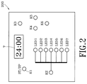
- a control panel 200 may be provided on the casing to allow a user to control the operation of the food treating device 100.
- a preferred embodiment of the control panel 200 may comprise a start/stop (ST/SP) key or switch for starting and/or stopping the operation of the food treating device 100, a mode selection key K2 for allowing a user to set or select a desired operation mode indicated by one of seven indicators, preferably light emitting diodes (LED) designated by LED1-LED7 in the drawings, each of which indicators LED1-LED7 designates a different operation mode that the food treating device 100 can perform, such as light baking, medium baking, dark baking (all for bread baking), manual operation, cake baking, jam making and rice cooking, a timer control key K3 for setting and controlling timer means which may be shown on a display 7, preferably a seven-segment display, which timer controls the operation cycle of the food treating device 100, two clock controlling keys K4 (hour) and K5 (minute) for setting and controlling hour and minute digits shown on the display 7 and an operation cancel key K6.
- ST/SP start/stop
- mode selection key K2 for allowing a user to set
- control panel 200 is only an example and that other arrangements may also be adopted provided that they provide the same control function of the present invention.
- the operation cycles may comprise in combination a stirring process, a fermentation process and a heating process.
- the operation cycle comprises a stirring process wherein dough for making breads is first stirred for 10 minutes, stop stirring for 5 minutes, stirred again for 15 more minutes, stop stirring for 20 minutes and then further stirred for 4 seconds. The so stirred dough is then left for fermentation for 55 minutes and then heated for 33, 40 or 47 minutes, depending upon the required baking result of the breaks, such as light, medium and dark.
- the operation cycle comprises stirring and heating which is respectively listed in the Table.
- the last operation mode in the Table is rice cooking which comprises heating process (20 minutes) only, for in cooking rice, no stirring and fermentation are required.
- the operation mode is the dark bread baking which performs the procedure listed in the Table, namely stirring the dough for three times with intermittent pauses inbetween. The dough is then left for fermentation. Thereafter, heat is provided by the heater means H for baking the dough.
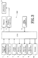
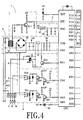
- Fig. 3 shows an embodiment of the functional block of a control circuit 300 of the food treating device 100 of the present invention, the corresponding circuit diagram thereof being illustrated in Figs. 4 and 5.
- the control circuit 300 of the present invention comprises a central processing unit (CPU) having electrically connected thereto an interrupt signal generator 1, a temperature detector 2, a power supply 3, a blower controller 4, a heater controller 5, a motor controller 6, the display 7, an indicator controller 8, a display controller 9 associated with the display 7, an key input controller 10 and, preferably, a buzzer BZ.
- the CPU controls the operation and actuation of these circuits 1-10 and BZ to receive signals therefrom, process the received signals, send control signals thereto to control the operation of the whole device 100.
- the central processing unit CPU may comprises a single chip microprocessor, such as chip code TMP47C440AN provided by Toshiba Co., Japan, of which the pins are defined as follows:
- the temperature detector 2 serves to provide temperature detection of the cooking temperature of the food treating device 100.
- the temperature detector circuit 2 comprises a thermal sensor 21 which, although not explicitly shown in the drawings but quite apparently, is disposed inside the outer housing A or the inner housing B for detecting the temperature thereof.
- the thermal sensor 21 which receives a 5V DC voltage may generate an analog temperature signal which is applied to pin R40 of the CPU via a dividing resistor 22. The analog temperature signal is divided by the dividing resistor 22 and the divided signal is then applied to R40 pin of the CPU.
- the motor controller circuit 6 is to control the operation of the motor M which is to rotate, via the transmission belt C, the stirring rod R within the inner housing B.
- the motor controller circuit 6 receives a signal from the CPU via pin R43.
- the signal is processed by a Darlington circuit constituted by two transistors Q61 and Q62 to control a relay RL1 which in turn controls the ON/OFF state of the motor M.
- the heater controller circuit 5 is to control the operation of the heater H which is mounted on the inner housing B and thus provides a high temperature to the inner housing B to cook the food inside the inner housing B. Similar to the motor controller circuit 6, the heater controller circuit 5 receives a signal from the CPU via pin R42. The signal is processed by a Darlington circuit constituted by two transistors Q51 and Q52 to control a relay RL2 which in turn controls the ON/OFF state of the heater H.
- the blower controller circuit 4 is to control the operation of the blower fan F to supply air into the outer housing A and to cause air to circulate inside the outer housing A so as to provide a uniform temperature distribution inside the outer housing A.
- the blower controller circuit 4 receives a signal from the CPU via pin R41 which is processed by a fan driving circuit constituted by a transistor Q41 and a triac Q42 to control the operation of the blower fan F.
- the interrupt signal generator 1 provides an interrupt signal to the CPU for synchronizing the CPU with the frequency of the external AC power source.
- the interrupt signal generator 1 comprises a transistor Q11 of which the base is connected the secondary winding of the transformer 31 of the power supply circuit 3. Due to the fact that AC signal existing in the secondary winding of the transformer 31 has a frequency exactly the same as that of the external AC power applied to the power supply circuit 3 (for example, 50 Hz or 60 Hz), the interrupt signal generator 1 sends out a series of pulses of such a frequency to the INT pin of the CPU to synchronize the CPU with such a frequency.
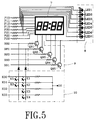
- the provision of the display 7 is to allow the user to monitor the operation of the food treating device 100.
- scanning method is adapted to display messages on the display 7, namely display control signals from output pins R80, R81, R83 and R90 of the CPU are respectively and sequentially applied to transistors Q91-Q94 of the display controller circuit 9 so as to sequentially enable the four digit units of the seven segment display.
- the display signal to the four digit units are transmitted from pins P10-P13 and P20-P23 of the CPU to show desired messages on the display 7.
- the seven LED indicators LED1-LED7 of the indicator controller circuit 8 are respectively connected to pins P10-P13 and P20-P22 to receive signals from the CPU. Under this situation, a switch, which in this case is a transistor Q95, is provided to switch between the display 7 and the indicator controller circuit 8. This transistor Q95 is connected to pin R91 of the CPU and controlled thereby.
- An example of the operation of the transistor Q95 is that when a control signal is generated at pin R91, signals from pins P10-P13 and P20-P23 are applied to the seven LED indicators LED1-LED7. If no such control signal exists, the signals of P10-P13 and P20-P23 are applied to the display 7.
- Key input controller 10 provides connections between the keys K1-K6 and the CPU. Once the keys K1-K6 are actuated, signals generated thereby are sent to the CPU.
- the buzzer BZ provides an audio warning signal to the user.
- the buzzer BZ may sound when the actuation of the keys K1-K6 are actually received by the CPU.
Landscapes
- Life Sciences & Earth Sciences (AREA)
- Engineering & Computer Science (AREA)
- Food Science & Technology (AREA)
- Baking, Grill, Roasting (AREA)
Priority Applications (1)
| Application Number | Priority Date | Filing Date | Title |
|---|---|---|---|
| EP93119474A EP0659342A1 (fr) | 1993-12-02 | 1993-12-02 | Appareil multi-fonction pour le traitement de produits alimentaires |
Applications Claiming Priority (1)
| Application Number | Priority Date | Filing Date | Title |
|---|---|---|---|
| EP93119474A EP0659342A1 (fr) | 1993-12-02 | 1993-12-02 | Appareil multi-fonction pour le traitement de produits alimentaires |
Publications (1)
| Publication Number | Publication Date |
|---|---|
| EP0659342A1 true EP0659342A1 (fr) | 1995-06-28 |
Family
ID=8213462
Family Applications (1)
| Application Number | Title | Priority Date | Filing Date |
|---|---|---|---|
| EP93119474A Withdrawn EP0659342A1 (fr) | 1993-12-02 | 1993-12-02 | Appareil multi-fonction pour le traitement de produits alimentaires |
Country Status (1)
| Country | Link |
|---|---|
| EP (1) | EP0659342A1 (fr) |
Cited By (3)
| Publication number | Priority date | Publication date | Assignee | Title |
|---|---|---|---|---|
| EP1527723A4 (fr) * | 2003-08-10 | 2007-07-04 | Jiangang Guo | Robot boulanger permettant de cuire du riz |
| CN106472624A (zh) * | 2016-12-10 | 2017-03-08 | 湖北沛丰粮油股份有限公司 | 面条烘干房悬挂传输链电器控制系统 |
| CN108903677A (zh) * | 2018-08-01 | 2018-11-30 | 杭州老板电器股份有限公司 | 烤箱及烤箱的控制方法 |
Citations (8)
| Publication number | Priority date | Publication date | Assignee | Title |
|---|---|---|---|---|
| EP0219077A2 (fr) * | 1985-10-12 | 1987-04-22 | Funai Electric Company Limited | Appareil de production de pain |
| EP0295723A1 (fr) * | 1983-07-08 | 1988-12-21 | Hosiden Corporation | Moyen de pétrissage pour un dispositif de cuisson de pain |
| GB2213698A (en) * | 1987-06-05 | 1989-08-23 | Matsushita Electric Industrial Co Ltd | Bread making machine |
| US4903587A (en) * | 1987-04-02 | 1990-02-27 | Hitachi Heating Appliances Co., Ltd. | Automatic baking apparatus |
| GB2222359A (en) * | 1988-09-05 | 1990-03-07 | Toshiba Kk | Bread baking apparatus |
| GB2222930A (en) * | 1988-08-29 | 1990-03-28 | Samsung Electronics Co Ltd | Apparatus for and method of baking bread and making yoghurt |
| US4984512A (en) * | 1989-10-11 | 1991-01-15 | Zojirushi Corporation | Automatic bread-making device |
| US5076153A (en) * | 1989-01-13 | 1991-12-31 | Zojirushi Corporation | Automatic bread-making device |
-
1993
- 1993-12-02 EP EP93119474A patent/EP0659342A1/fr not_active Withdrawn
Patent Citations (8)
| Publication number | Priority date | Publication date | Assignee | Title |
|---|---|---|---|---|
| EP0295723A1 (fr) * | 1983-07-08 | 1988-12-21 | Hosiden Corporation | Moyen de pétrissage pour un dispositif de cuisson de pain |
| EP0219077A2 (fr) * | 1985-10-12 | 1987-04-22 | Funai Electric Company Limited | Appareil de production de pain |
| US4903587A (en) * | 1987-04-02 | 1990-02-27 | Hitachi Heating Appliances Co., Ltd. | Automatic baking apparatus |
| GB2213698A (en) * | 1987-06-05 | 1989-08-23 | Matsushita Electric Industrial Co Ltd | Bread making machine |
| GB2222930A (en) * | 1988-08-29 | 1990-03-28 | Samsung Electronics Co Ltd | Apparatus for and method of baking bread and making yoghurt |
| GB2222359A (en) * | 1988-09-05 | 1990-03-07 | Toshiba Kk | Bread baking apparatus |
| US5076153A (en) * | 1989-01-13 | 1991-12-31 | Zojirushi Corporation | Automatic bread-making device |
| US4984512A (en) * | 1989-10-11 | 1991-01-15 | Zojirushi Corporation | Automatic bread-making device |
Cited By (4)
| Publication number | Priority date | Publication date | Assignee | Title |
|---|---|---|---|---|
| EP1527723A4 (fr) * | 2003-08-10 | 2007-07-04 | Jiangang Guo | Robot boulanger permettant de cuire du riz |
| CN106472624A (zh) * | 2016-12-10 | 2017-03-08 | 湖北沛丰粮油股份有限公司 | 面条烘干房悬挂传输链电器控制系统 |
| CN108903677A (zh) * | 2018-08-01 | 2018-11-30 | 杭州老板电器股份有限公司 | 烤箱及烤箱的控制方法 |
| CN108903677B (zh) * | 2018-08-01 | 2020-09-29 | 杭州老板电器股份有限公司 | 烤箱及烤箱的控制方法 |
Similar Documents
| Publication | Publication Date | Title |
|---|---|---|
| US5415081A (en) | Bread making apparatus | |
| US6011243A (en) | Holding cabinet and method and apparatus for controlling a holding cabinet | |
| JP2525736B2 (ja) | 電気オ―ブンの電気消費体の制御装置 | |
| US5296683A (en) | Preheating method and apparatus for use in a food oven | |
| US7589299B2 (en) | Electronic power control for cooktop heaters | |
| JPS58220385A (ja) | 電子制御式調理器 | |
| US5182439A (en) | Method and apparatus for operating a food oven | |
| JP2004093105A (ja) | ヒーターを備えた調理装置とその制御方法 | |
| US6425319B1 (en) | Griller with presettable cooking temperature and timed alarm capability | |
| US5628240A (en) | Bread making apparatus | |
| EP0659342A1 (fr) | Appareil multi-fonction pour le traitement de produits alimentaires | |
| KR20040017188A (ko) | 히터를 구비한 조리기 | |
| JPH05332559A (ja) | 加熱調理器 | |
| JP3258958B2 (ja) | 電子レンジ | |
| EP0291302B1 (fr) | Cuisinière électrique | |
| KR100303856B1 (ko) | 전자제어식 튀김조리장치 | |
| JPH06237853A (ja) | 炊飯器 | |
| JPH0134583B2 (fr) | ||
| JPH02146424A (ja) | 加熱調理器 | |
| JPH0140248B2 (fr) | ||
| JPH09108116A (ja) | 製パン器の誤操作警報装置 | |
| KR100225626B1 (ko) | 전자렌지의 조리메뉴입력장치 | |
| KR0146828B1 (ko) | 전자렌지의 램프구동장치 | |
| KR200199014Y1 (ko) | 온장고 부패 방지장치 | |
| JPH0132892B2 (fr) |
Legal Events
| Date | Code | Title | Description |
|---|---|---|---|
| PUAI | Public reference made under article 153(3) epc to a published international application that has entered the european phase |
Free format text: ORIGINAL CODE: 0009012 |
|
| 17P | Request for examination filed |
Effective date: 19940629 |
|
| AK | Designated contracting states |
Kind code of ref document: A1 Designated state(s): DE ES FR GB IT |
|
| STAA | Information on the status of an ep patent application or granted ep patent |
Free format text: STATUS: THE APPLICATION IS DEEMED TO BE WITHDRAWN |
|
| 18D | Application deemed to be withdrawn |
Effective date: 19960702 |