EP0659453A1 - Support de bicyclette pour l'entraînement - Google Patents
Support de bicyclette pour l'entraînement Download PDFInfo
- Publication number
- EP0659453A1 EP0659453A1 EP94100385A EP94100385A EP0659453A1 EP 0659453 A1 EP0659453 A1 EP 0659453A1 EP 94100385 A EP94100385 A EP 94100385A EP 94100385 A EP94100385 A EP 94100385A EP 0659453 A1 EP0659453 A1 EP 0659453A1
- Authority
- EP
- European Patent Office
- Prior art keywords
- bicycle
- rotary
- frame
- stand according
- exercise stand
- Prior art date
- Legal status (The legal status is an assumption and is not a legal conclusion. Google has not performed a legal analysis and makes no representation as to the accuracy of the status listed.)
- Withdrawn
Links
- 239000002184 metal Substances 0.000 claims description 7
- 230000002093 peripheral effect Effects 0.000 claims description 4
- 230000004907 flux Effects 0.000 description 9
- 238000010276 construction Methods 0.000 description 3
- 230000001351 cycling effect Effects 0.000 description 2
- 229920003023 plastic Polymers 0.000 description 2
- 239000004033 plastic Substances 0.000 description 2
- 229910000831 Steel Inorganic materials 0.000 description 1
- 238000003491 array Methods 0.000 description 1
- 238000006073 displacement reaction Methods 0.000 description 1
- 230000000694 effects Effects 0.000 description 1
- 239000000463 material Substances 0.000 description 1
- 238000013021 overheating Methods 0.000 description 1
- 229920000915 polyvinyl chloride Polymers 0.000 description 1
- 239000004800 polyvinyl chloride Substances 0.000 description 1
- 238000002360 preparation method Methods 0.000 description 1
- 239000011347 resin Substances 0.000 description 1
- 229920005989 resin Polymers 0.000 description 1
- 125000006850 spacer group Chemical group 0.000 description 1
- 239000010959 steel Substances 0.000 description 1
Images







Classifications
-
- A—HUMAN NECESSITIES
- A63—SPORTS; GAMES; AMUSEMENTS
- A63B—APPARATUS FOR PHYSICAL TRAINING, GYMNASTICS, SWIMMING, CLIMBING, OR FENCING; BALL GAMES; TRAINING EQUIPMENT
- A63B69/00—Training appliances or apparatus for special sports
- A63B69/16—Training appliances or apparatus for special sports for cycling, i.e. arrangements on or for real bicycles
-
- A—HUMAN NECESSITIES
- A63—SPORTS; GAMES; AMUSEMENTS
- A63B—APPARATUS FOR PHYSICAL TRAINING, GYMNASTICS, SWIMMING, CLIMBING, OR FENCING; BALL GAMES; TRAINING EQUIPMENT
- A63B69/00—Training appliances or apparatus for special sports
- A63B69/16—Training appliances or apparatus for special sports for cycling, i.e. arrangements on or for real bicycles
- A63B2069/164—Training appliances or apparatus for special sports for cycling, i.e. arrangements on or for real bicycles supports for the rear of the bicycle, e.g. for the rear forks
- A63B2069/165—Training appliances or apparatus for special sports for cycling, i.e. arrangements on or for real bicycles supports for the rear of the bicycle, e.g. for the rear forks rear wheel hub supports
-
- A—HUMAN NECESSITIES
- A63—SPORTS; GAMES; AMUSEMENTS
- A63B—APPARATUS FOR PHYSICAL TRAINING, GYMNASTICS, SWIMMING, CLIMBING, OR FENCING; BALL GAMES; TRAINING EQUIPMENT
- A63B21/00—Exercising apparatus for developing or strengthening the muscles or joints of the body by working against a counterforce, with or without measuring devices
- A63B21/005—Exercising apparatus for developing or strengthening the muscles or joints of the body by working against a counterforce, with or without measuring devices using electromagnetic or electric force-resisters
- A63B21/0051—Exercising apparatus for developing or strengthening the muscles or joints of the body by working against a counterforce, with or without measuring devices using electromagnetic or electric force-resisters using eddy currents induced in moved elements, e.g. by permanent magnets
-
- A—HUMAN NECESSITIES
- A63—SPORTS; GAMES; AMUSEMENTS
- A63B—APPARATUS FOR PHYSICAL TRAINING, GYMNASTICS, SWIMMING, CLIMBING, OR FENCING; BALL GAMES; TRAINING EQUIPMENT
- A63B21/00—Exercising apparatus for developing or strengthening the muscles or joints of the body by working against a counterforce, with or without measuring devices
- A63B21/22—Resisting devices with rotary bodies
- A63B21/225—Resisting devices with rotary bodies with flywheels
-
- A—HUMAN NECESSITIES
- A63—SPORTS; GAMES; AMUSEMENTS
- A63B—APPARATUS FOR PHYSICAL TRAINING, GYMNASTICS, SWIMMING, CLIMBING, OR FENCING; BALL GAMES; TRAINING EQUIPMENT
- A63B2208/00—Characteristics or parameters related to the user or player
- A63B2208/12—Characteristics or parameters related to the user or player specially adapted for children
-
- A—HUMAN NECESSITIES
- A63—SPORTS; GAMES; AMUSEMENTS
- A63B—APPARATUS FOR PHYSICAL TRAINING, GYMNASTICS, SWIMMING, CLIMBING, OR FENCING; BALL GAMES; TRAINING EQUIPMENT
- A63B23/00—Exercising apparatus specially adapted for particular parts of the body
- A63B23/035—Exercising apparatus specially adapted for particular parts of the body for limbs, i.e. upper or lower limbs, e.g. simultaneously
- A63B23/04—Exercising apparatus specially adapted for particular parts of the body for limbs, i.e. upper or lower limbs, e.g. simultaneously for lower limbs
- A63B23/0476—Exercising apparatus specially adapted for particular parts of the body for limbs, i.e. upper or lower limbs, e.g. simultaneously for lower limbs by rotating cycling movement
Definitions
- This invention relates to an exercise stand for a bicycle, and more particularly to a bicycle exercise stand which holds the drive wheel of the bicycle clear of the floor surface and exerts a load on a drive wheel so that bicycle pedaling exercise simulates actual cycling.
- FIG. 9 A pair of tubular members 101, 102 extend perpendicular to the drawing sheet and parallel with each other for forming a frame 100.
- Two pairs of legs 103, 104 (only the leg on the near side is shown) which extend upward are mounted at ends of the tubular members 101, 102.
- the upper portions of the legs 104 are pivotally supported at the upper portions of the legs 103.
- a pair of holding members 105 (only one is shown), for firmly holding the hub 111 of the rear wheel, are mounted at the top ends of the legs 103.
- a loading device 106 is mounted on the tubular member 101, said device 106 generating a resistive force in accordance with the rotational speed of the rear wheel 111 .
- the loading device 106 includes a resistance generator 107, having a rotating shaft 108, and a small-diameter drive cylinder 109 which is mounted on the rotating shaft 108 and makes contact with the tire 112 of the rear wheel 111.
- the resistance generator 107 includes a pair of permanent magnets and a metallic rotary disk secured to the rotary shaft. The magnets are disposed on the opposite side and face each other. The rotation of the rotary disk results in eddy currents and exerts a load on the rotating rotary shaft.
- the drive cylinder 109 and the tread pattern are in contact with each other at every moment as the drive cylinder 109 rotates along with the rotation of the rear wheel 111.
- the constant load continuously transmitted to the rear wheel 111 from the cylinder 109 enables the user carry out the smooth pedaling operation.
- the contact of the drive cylinder with the tread pattern of the tire causes the noise.
- continuous contact without having any proper gap suppresses the sound wave to travel resulting in this noise not to be loud.
- the loading device 106 has the drive cylinder 109 with a small diameter.
- This construction causes the problem when a special bicycle, e. g. a cross-country bicycle, is used as the exercising material. More specifically, the construction disables the cylinder 109 from continuously contacting block type patterns 112a adjacent to one another in the circumferencial direction as shown in Fig. 14. Therefore, as the rear wheel 111 rotates, the corner of the next pattern 112a collides with the drive cylinder 109. This causes the magnitude of resistive force to be changeable, resulting in loud noise and unsmooth pedaling exercise.
- an exercise stand for a bicycle is diclosed.
- the stand includes a frame for supporting the drive wheel of the bicycle.
- the stand also has a loading device having a rotary drive member which rotates and contacts with a tread pattern provided with an outer peripheral surface of a tire as the drive wheel is rotated by the rotation of the pedals of the bicycle.
- the loading device is arranged to exert a resistive load to the drive wheel.
- the rotary drive member has an outer diameter enabling the rotary drive member to contact with a plurality of adjacent tread patterns circumferentially juxtaposing in a tire, wherein said the tread pattern is block type.
- an exercise stand supports a cross-country type bicycle.
- Fig. 1 shows an exercise stand for a bicycle set up on a floor surface.
- the stand has a frame 1 supporting a loading device 2.
- the frame 1 has a pair of tubular bases 3, 4 at a front and rear portions, respectively. Each pair of bases extend parallelly each other and positioned on the floor.
- a U-shaped portion 5 mounted on the front base 3 extends rearward inclining upward.
- a pair of legs 6, 7 are mounted on the rear base 4 oppose the U-shaped portion 5 and extend upward.
- the U-shaped portion 5 is pivotally linked from below to the opposing legs 6, 7 through pieces C fitted to the upper ends of the U-shaped portion 5.
- the portion 5 is in the pivoted position as shown by the dotted lines so as to fold the whole stand for storage.
- a holding cylinder portion 8 secured to the upper end of the right leg 6 extends horizontally.
- a positioning screw 9 is received by the cylinder 8.
- the inner end of the screw 9 projects inward from the cylinder 8.
- An adjusting knob 10 is mounted on the outer end (the right-hand end) of the screw 9.
- a locking knob 11 is fitted on the screw 9 between the knob 10 and the outer wall of the cylinder 8.
- a receiving sleeve 12 is mounted on the inner end of the screw 9. The amount of inward extension of the screw 9 is adjusted by the manipulating operation of the knob 10.
- a support arm 15 is pivotally attached to the left leg 7 by a pin 14.
- An cylinder portion 16 is mounted on the upper portion of this support arm 15, and a fitting sleeve 17 which projects inward from the cylinder 16 is mounted on the inner end of the cylinder 16.
- the support arm 15 is linked to the upper end of a lift rod 25.
- the lower end of the lift rod 25 is linked to a pedal 26 mounted on the leg 7.
- a first rotary shaft Ra which projects from the hub H of the rear wheel B is inserted into the sleeve 12, and positioning of the rear wheel B is thereby performed. Subsequently, the pedal 26 is operated to move the rod 25 in the substantially vertical direction. Therefore, the support arm 15 rotates about the pin 14 for switching the positions of the sleeve 17.
- the sleeve 17 is fitted onto the second rotation shaft Rb projecting from the hub H of the rear wheel B, and the rear wheel B is rotatably held by the sleeve 17 and the sleeve 12.
- the loading device 2 will now be described in detail.
- a metal bracket 41 is mounted on the rear base 4.
- an opposed pair of pieces 41a, 41b are formed at the respective ends of the bracket 41.
- a metal support 42 is pivotally mounted between the two pieces 41a, 41b by a bolt 43 near its base portion.
- the support 42 has a pair of arms 42a, 42b and a link 42c connecting two arms 42a, 42b.
- a shaft 44 is mounted between the ends of the arms 42a, 42b.
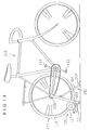
- a steel drive drum 46 which also serves as a flywheel, is rotatably supported on the shaft 44 by way of a pair of bearings 45, and the tire 91 of the rear wheel B of the bicycle 90 makes contact with the outer peripheral surface of this drive drum 46.
- the drive drum 46 has an outer diameter so as to contact with a plurality of block tread patterns 91a adjacently disposed in the circumferential direction of a tire 91.
- a plate 47 is mounted on the central portion of the arm portion 42b, and a resistance generator 48 exerting a resistive force on the rear wheel B is mounted on the plate 47.
- the rotary shaft 49 of the generator 48 projects out through the arm 42b, but does not interfere with the arm 42b.
- a pulley 50 mounted on the outer end of the rotary shaft 49 is operably connected to the drum by way of a V-belt 51.
- a pair of engaging bolts 52 (only one of which is illustrated) are screwed into the central portions of the arm portions 42a, 42b.
- a pair of tension springs 53 urging the support 42 toward the frame 1 are disposed between the bolts 52 and the bracket 41.
- a holding lever 54 is rotatably mounted on the outer surface the piece 41a by means of a pin 55.
- An L-shaped elongated hole 56 including a guide 56a extending to the pin 55 and a stopper 56b intersecting with the guide 56a at the other end of the lever 54, is provided with the lever 54.
- a pin 57 mounted on and projecting from the arm 42a, undetachably passes through the hole 56 so as to move along the hole 56.
- the pin 55 supports a U-shaped spring 58 interposed between the lever 54 and the piece 41a. Ends of the spring 58 are abuts a projection 59 formed on the piece 41a, and a projection 60 formed on the lever 54, respectively. The urging force of the spring 58 causes the lever 54 to be biased to the support 42.
- a pair of plastic covers 61 made of a hard artificial resin such as polyvinyl chloride, are secured to the outer surface of the arm 42a, 42b by screws 62.
- a plurality of spacer plates 63 are securely disposed between the covers 61 by screws 64 for maintaining the clearance between the covers 61.
- An inner case 65 is mounted on the plate 47 by means of screws 66.
- the rotary shaft 49 is rotatably mounted to the case 65 by means of a pair of bearings 67.
- a metal rotary disk 68 is mounted via a bush 69 to the inner end of the shaft 49.
- An outer case 70 having a substantially bowl shape and mounted on the inner case 65 covers the rotary disk 68.
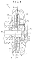
- a plurality of fixed permanent magnets 71 are mounted through the plate 72 on the inner surface of the case 65 in the vicinity of to the rotary disk 68. As shown in Fig. 9, these permanent magnets 71 are arranged on the mounting plate 72 in a circular sequence with adjacent polarities being alternating.
- a plurality of holes 68a formed in the inner peripheral portion of the rotary disk 68 are juxtaposed in the circumferential direction for preventing the rotary disk 68 from overheating.
- a support plate 73 is rotatably supported on the inner surface of the outer case 70.
- the plate 73 is held stationary by a plurality of legs 74 mounted on the outer case 70.
- a plurality of movable permanent magnets 75 mounted on the plate 73 face the permanent magnets 71. These permanent magnets 75 are juxtaposed on the plate 73 in a circular sequence in such a way that adjacent poles are alternate.
- the permanent magnets 75 work in conjunction with the permanent magnets 71, when the rotary disk 68 is rotating, to induce eddy currents on the rotary disk 68.
- a rotation resistance is exerted in the rotary disk 68 by these eddy currents, and a load is applied to the pedals 92.
- an adjusting knob 76 for adjusting the load applied to the pedals 92 is mounted on the central portion of the outer surface of the case 70. As shown in Fig. 8, the knob 76 is rotatable with respect to the case 70 about a pin 77. The knob 76 is also linked to the plate 73, via a plurality of link pieces 79 on a plate 78 mounted in the knob 76. A point mark 80 is provided on the end surface of the knob 76. A scale 81 for indicating the setting value of the load applied to the pedals 92 is provided on the surface of the case 70.
- the mark 80 When the mark 80 is in the position corresponding to "L" of the scale 81, it indicates a low load. In this state, the permanent magnets 75 and the permanent magnets 71 are positioned in such a way that the opposed magnets 71, 75 have identical polarities. When the mark 80 is in the position pointing to the "H” of the scale 81, it selects a high load. In this state, the opposed permanent magnets 71, 75 have alternating polarities. The knob 76 is moved between the "H” and "L” of the scale 81, the desired magnitude of the load applied to the pedals 92 is selected.
- a ball mounted to the case 70 via a spring 83 is urged against the knob 76 for selecting one of holes 84 provided with the link plate 78, so that the magnets 75 are held in the desired setting position indicated by the mark 80.
- the exercise stand is operated as below.
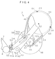
- the loading device 2 held upright as shown in Fig. 3, is pivoted clockwise (away from the frame 1) against the force of the springs 53.
- the pin 57 rotates together with the support 42 and engages the guide 54 for rotating the lever 54.
- the lever 54 is biased by the spring 58 and further pivoted clockwise for bringing the stopper 56b into the engagement with the pin 57. Since the movement of the pin 57 is restricted by the stopper 56b, the loading device 2 is held in the standby position shown in Fig. 4.
- the rear portion of the bicycle 90 is carefully held up by the user with both hands so that rotary shaft Ra is kept in the sleeve 12.
- the pedal 26 is operated by the user with feet for moving the rod 25 in the substantially vertical direction, resulting in the arm 15 to pivot about the pin 14 and shifting the position of the sleeve 17.
- the sleeve 17 is fitted onto the second rotary shaft Rb projecting from the hub H of the rear wheel B. Therefore, the rear wheel B is rotatably held by the sleeves 12, 17.
- the drum 46 is held to be slightly urged downward until the engagement of the stopper 56b and the pin 57 is released by the rotating movement of the lever 54 against the force of the spring 58. Then, the loading device 2 rotates toward the frame 1 by the force of the springs 53. The loading device 2 stops to rotate when the drum 46 abuts against the tire 91 of the rear wheel B. In this stationary position or non-working position, the drum 46 is pressed against the tire 91 by the force of the springs 53. Thus, the preparatory positioning of the bicycle 90 for exercise is complete. In this state, the drum 46 makes contact with the block type tread patterns adjacently disposed in the circumferential direction of the tire 91.
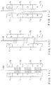
- the mark 80 pointing to the "L" of the scale 81 in Fig. 10 arranges the magnets 71, 75 having the identical polarities as shown in Fig. 11(a) In this state, no flux passes through the rotary disk 68. Generally, eddy current is generated according to the flux and the rotational motion of the rotary disk 68 for exerting the resistive load for hindering the rotation of the rotary disk 68. Therefore, no flux results in no eddy current and, thus, no resistive force applied to the pedal.
- the mark 80 selecting the "H" of the scale 81 in Fig. 10 arranges the magnets 71, 75 having the alternating polarities as shown in Fig. 11(c).
- the number of flux increases and the resistance becomes larger.
- the permanent magnets 75 are continuously moved, with respect to the permanent magnets 71, in the circumferential direction from the position shown in Fig. 11(a) through the intermediate position shown in Fig. 11(b).
- the number of flux increases linearly, and, accordingly, the eddy current also linearly becomes greater. Therefore, the load magnitude varying in accordance with the degree of angular displacement the knob 76 is represented by a line shown in Fig. 12. Accordingly, the desired magnitude of resistive load is easily obtained by turning the knob 76 in respect with the scale 81.
- the drive drum 46 makes surface contact with the tread pattern of the tire at every moment.
- the magnitude of the resistive load applied to the rear wheel B can be kept substantially constant resulting in the smooth pedaling exercise.
- collision of the corners of the tread patterns 91a, moving along with the rotation of the rear wheel B, with the drive drum 46 is prevented, and the generation of noise due to the contact between the drum 46 and the tire 91 is suppressed.
- the loading device 2 in this embodiment has the drum 46 rotatably supported on the support 42 rotated by the force of the springs 53.
- the drive drum 46 is pushed against the rear wheel B of the bicycle for applying the resistive force to the wheel B.
- This construction enables the exercise stand to exert a resistive load to any wheels regardless of the diameters, resulting in the versatile applicability to the wide range of bicycles with a different wheel diameters, from an adult's bicycle with a large wheel diameter to a child's bicycle with a small wheel diameter.
- the drive drum 46 serving as a flywheel assists the user to experience the actual-cycling-feeling. Furthermore, this drum 46 enables an actual flywheel to be omitted for minimizing the size of l size of the apparatus.
- the bicycle exercise stand of this embodiment can be used to apply resistive load to the bicycle tires having rib type or lug type tread patterns.
Landscapes
- Health & Medical Sciences (AREA)
- General Health & Medical Sciences (AREA)
- Physical Education & Sports Medicine (AREA)
- Tires In General (AREA)
- Dynamo-Electric Clutches, Dynamo-Electric Brakes (AREA)
Applications Claiming Priority (2)
| Application Number | Priority Date | Filing Date | Title |
|---|---|---|---|
| JP98219/93 | 1993-04-23 | ||
| JP9821993A JPH06304266A (ja) | 1993-04-23 | 1993-04-23 | 自転車用運動器具 |
Publications (1)
| Publication Number | Publication Date |
|---|---|
| EP0659453A1 true EP0659453A1 (fr) | 1995-06-28 |
Family
ID=14213862
Family Applications (1)
| Application Number | Title | Priority Date | Filing Date |
|---|---|---|---|
| EP94100385A Withdrawn EP0659453A1 (fr) | 1993-04-23 | 1994-01-12 | Support de bicyclette pour l'entraînement |
Country Status (2)
| Country | Link |
|---|---|
| EP (1) | EP0659453A1 (fr) |
| JP (1) | JPH06304266A (fr) |
Cited By (3)
| Publication number | Priority date | Publication date | Assignee | Title |
|---|---|---|---|---|
| CN1873734B (zh) * | 2005-05-30 | 2010-10-20 | 本田技研工业株式会社 | 自行车模拟系统 |
| EP2653198A1 (fr) * | 2012-04-19 | 2013-10-23 | The Bicycle Corporation Pty Ltd | Accessoire de cyclisme et procédé d'utilisation |
| CN104826319A (zh) * | 2015-04-29 | 2015-08-12 | 徐峰 | 便携式自行车减速装置 |
Families Citing this family (1)
| Publication number | Priority date | Publication date | Assignee | Title |
|---|---|---|---|---|
| JPH1024137A (ja) * | 1996-07-10 | 1998-01-27 | Minoura:Kk | 自転車用運動器具 |
Citations (5)
| Publication number | Priority date | Publication date | Assignee | Title |
|---|---|---|---|---|
| US4826150A (en) * | 1986-02-20 | 1989-05-02 | Minoura Carrier & Stand Works Co., Ltd. | Resistance applying means for exercising apparatus |
| EP0341752A2 (fr) * | 1988-05-13 | 1989-11-15 | R.T.S. Trainer Corporation | Dispositif d'entraînement pour vélo pourvu d'un mécanisme de montage rapide |
| US4982953A (en) * | 1990-03-26 | 1991-01-08 | Makishi Todd K | Exercise apparatus |
| US5026047A (en) * | 1989-09-29 | 1991-06-25 | Kosecoff Irving W | Quick release mechanism for bicycle trainer |
| US5042795A (en) * | 1989-09-28 | 1991-08-27 | Bursik Thomas A | Interchangeable dual position training stand and work stand for bicyclists |
-
1993
- 1993-04-23 JP JP9821993A patent/JPH06304266A/ja not_active Withdrawn
-
1994
- 1994-01-12 EP EP94100385A patent/EP0659453A1/fr not_active Withdrawn
Patent Citations (5)
| Publication number | Priority date | Publication date | Assignee | Title |
|---|---|---|---|---|
| US4826150A (en) * | 1986-02-20 | 1989-05-02 | Minoura Carrier & Stand Works Co., Ltd. | Resistance applying means for exercising apparatus |
| EP0341752A2 (fr) * | 1988-05-13 | 1989-11-15 | R.T.S. Trainer Corporation | Dispositif d'entraînement pour vélo pourvu d'un mécanisme de montage rapide |
| US5042795A (en) * | 1989-09-28 | 1991-08-27 | Bursik Thomas A | Interchangeable dual position training stand and work stand for bicyclists |
| US5026047A (en) * | 1989-09-29 | 1991-06-25 | Kosecoff Irving W | Quick release mechanism for bicycle trainer |
| US4982953A (en) * | 1990-03-26 | 1991-01-08 | Makishi Todd K | Exercise apparatus |
Cited By (4)
| Publication number | Priority date | Publication date | Assignee | Title |
|---|---|---|---|---|
| CN1873734B (zh) * | 2005-05-30 | 2010-10-20 | 本田技研工业株式会社 | 自行车模拟系统 |
| EP2653198A1 (fr) * | 2012-04-19 | 2013-10-23 | The Bicycle Corporation Pty Ltd | Accessoire de cyclisme et procédé d'utilisation |
| EP3431151A1 (fr) * | 2012-04-19 | 2019-01-23 | Ward, Geoffrey Allan | Accessoire de cyclisme et procédé d'utilisation |
| CN104826319A (zh) * | 2015-04-29 | 2015-08-12 | 徐峰 | 便携式自行车减速装置 |
Also Published As
| Publication number | Publication date |
|---|---|
| JPH06304266A (ja) | 1994-11-01 |
Similar Documents
| Publication | Publication Date | Title |
|---|---|---|
| US9044635B2 (en) | Exercise bicycle with magnetic flywheel brake | |
| US5522781A (en) | Exercise stand for a bicycle | |
| US6857992B1 (en) | Magnetic resistance system for a roller-type bicycle trainer | |
| US5728029A (en) | Bicycle exercise device | |
| US5833583A (en) | Exerciser having foot supports moving along elliptical path | |
| US7011607B2 (en) | Variable magnetic resistance unit for an exercise device | |
| US4627616A (en) | Exercise apparatus | |
| US20100069205A1 (en) | Magnetic resistance device for exerciser | |
| US5324242A (en) | Exercise apparatus with magnet-type resistance generator | |
| JPS62194873A (ja) | 室内運動具における抵抗付与装置 | |
| US7264576B2 (en) | Elliptical exercise device | |
| US11779802B2 (en) | Fitness machine and resistance device thereof | |
| CA2073110C (fr) | Ergocycle a position horizontale et a siege reglable a la verticale | |
| US6780143B2 (en) | Eccentric cycling trainer | |
| WO2017051332A1 (fr) | Appareil de résistance pour bicyclette à courant de foucault | |
| US6132341A (en) | Cycling exerciser having a rotatable handle | |
| EP0529145A1 (fr) | Support de bicyclette pour l'entraînement | |
| US5816818A (en) | Training device for riding a unicycle | |
| US20070054782A1 (en) | Exercise apparatus | |
| CN112546551A (zh) | 可实现三维度踩踏训练的椭圆机 | |
| KR101783154B1 (ko) | 자전거형 전신운동기구 | |
| EP0603454A1 (fr) | Appareil à résistance pour exercice | |
| JPH06304266A (ja) | 自転車用運動器具 | |
| CN201643537U (zh) | 迷你健身车 | |
| US12533547B2 (en) | Stationary bike capable of adjusting resistance and slope simultaneously |
Legal Events
| Date | Code | Title | Description |
|---|---|---|---|
| PUAI | Public reference made under article 153(3) epc to a published international application that has entered the european phase |
Free format text: ORIGINAL CODE: 0009012 |
|
| AK | Designated contracting states |
Kind code of ref document: A1 Designated state(s): DE FR IT NL |
|
| 17P | Request for examination filed |
Effective date: 19951227 |
|
| 17Q | First examination report despatched |
Effective date: 19980319 |
|
| STAA | Information on the status of an ep patent application or granted ep patent |
Free format text: STATUS: THE APPLICATION IS DEEMED TO BE WITHDRAWN |
|
| 18D | Application deemed to be withdrawn |
Effective date: 19980730 |