EP0659502B1 - Anlage zum Streckschmieden von Rohblöcken - Google Patents
Anlage zum Streckschmieden von Rohblöcken Download PDFInfo
- Publication number
- EP0659502B1 EP0659502B1 EP93120370A EP93120370A EP0659502B1 EP 0659502 B1 EP0659502 B1 EP 0659502B1 EP 93120370 A EP93120370 A EP 93120370A EP 93120370 A EP93120370 A EP 93120370A EP 0659502 B1 EP0659502 B1 EP 0659502B1
- Authority
- EP
- European Patent Office
- Prior art keywords
- forging
- forging machine
- stretch
- cropping
- installation
- Prior art date
- Legal status (The legal status is an assumption and is not a legal conclusion. Google has not performed a legal analysis and makes no representation as to the accuracy of the status listed.)
- Expired - Lifetime
Links
- 238000005242 forging Methods 0.000 title claims abstract description 46
- 238000009434 installation Methods 0.000 title abstract 4
- 230000010354 integration Effects 0.000 abstract description 3
- 230000032258 transport Effects 0.000 description 2
- 239000000956 alloy Substances 0.000 description 1
- 238000004519 manufacturing process Methods 0.000 description 1
- 239000000463 material Substances 0.000 description 1
- 238000000034 method Methods 0.000 description 1
- 239000011265 semifinished product Substances 0.000 description 1
- 239000007858 starting material Substances 0.000 description 1
Images


Classifications
-
- B—PERFORMING OPERATIONS; TRANSPORTING
- B21—MECHANICAL METAL-WORKING WITHOUT ESSENTIALLY REMOVING MATERIAL; PUNCHING METAL
- B21J—FORGING; HAMMERING; PRESSING METAL; RIVETING; FORGE FURNACES
- B21J1/00—Preparing metal stock or similar ancillary operations prior, during or post forging, e.g. heating or cooling
- B21J1/04—Shaping in the rough solely by forging or pressing
-
- B—PERFORMING OPERATIONS; TRANSPORTING
- B21—MECHANICAL METAL-WORKING WITHOUT ESSENTIALLY REMOVING MATERIAL; PUNCHING METAL
- B21J—FORGING; HAMMERING; PRESSING METAL; RIVETING; FORGE FURNACES
- B21J7/00—Hammers; Forging machines with hammers or die jaws acting by impact
- B21J7/02—Special design or construction
- B21J7/14—Forging machines working with several hammers
-
- B—PERFORMING OPERATIONS; TRANSPORTING
- B23—MACHINE TOOLS; METAL-WORKING NOT OTHERWISE PROVIDED FOR
- B23D—PLANING; SLOTTING; SHEARING; BROACHING; SAWING; FILING; SCRAPING; LIKE OPERATIONS FOR WORKING METAL BY REMOVING MATERIAL, NOT OTHERWISE PROVIDED FOR
- B23D31/00—Shearing machines or shearing devices covered by none or more than one of the groups B23D15/00 - B23D29/00; Combinations of shearing machines
Definitions
- raw blocks cast in molds are used as the starting material for economic and technical reasons, and are converted into blooms by open-die stretch forging.
- stretch forging it is necessary to scoop the block at its ends one or more times, i.e. to cut the ends of inferior quality. If forging presses with a lower and a moving upper saddle are used for stretch forging, scooping is easy to do by exchanging forged saddles for knife saddles.
- radial forming forging machines Due to their high forming capacity, radial forming forging machines, which act on the forging at the same time with mostly four radially arranged tools, are also particularly suitable for stretch forging, especially when materials that are difficult to form or can only be formed in a narrow temperature window are to be forged. Since the use of knife saddles in radial forming forging machines is hardly practical, the cropping must take place outside the line in which the radial forming forging machine, a manipulator or two manipulators arranged on both sides of the forging machine, as well as charging devices for the attachment and Removal and, if necessary, support and rotation of the blocks are combined to form a system. As a result, the cropping is associated with considerable loss of time and heat, which the invention seeks to avoid.
- the invention relates to such a system equipped with a radial forming forging machine for stretch forging of ingots, which is characterized according to the invention by a cropping shear integrated with the forging machine.
- This integration of forging machine and cropping shear enables the cropping shear to be brought into the line of the system in such a way that the forging process and the manipulation of the forging block necessary for this is possible without hindrance.
- the integration of the forging machine and cropping shears is particularly space-saving and thus particularly advantageous if, according to a further feature of the invention, the forging machine and cropping shears are provided with a frame common to them.
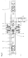
- the forging plant shown in Figures 1 and 2 consists of a forging machine 1 with integrated cropping shears 2 with which two manipulators 3 and 4 are arranged in a line.
- support rollers 6 carried in the exemplary embodiment by swivel arms 5 in the immediate vicinity on both sides of the forging machine 1 and a block carriage 7 with a rotatable, trough-shaped support 8 for a forging to be fed in or out.
- Cross transport devices 9 can be provided for the removal of long forgings.
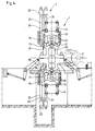
- the forging machine 1 consists - for details, see FIGS. 3 and 4 - of a frame 10 in which four plungers 11 are guided, which are equipped with tools 12 on the end face.
- the plungers 11 are movable radially to the system axis S in an X-shaped plane perpendicular to the system axis, offset by 90 ° to one another.
- the plungers 11 are driven by piston-cylinder units 13, which are supported on cross members 14, which are connected to the frame 10 by prestressed columns 15.
- the frame 10 is provided on one end face vertically above and below the system axis with molded sockets 16 which serve to guide an upper and a lower shear tool carrier 17, 18.
- a forging block can be severed with a knife 19 on the shear tool carrier 17, for example a cropping piece can be severed.
- the shear tool carrier 17 is moved with its knife 19 by a piston-cylinder unit 21 and the shear tool carrier 18 with its saddle 20 by a piston-cylinder unit 22, the piston-cylinder units 21 and 22 each being supported by a cross member 23, which are connected to the associated socket 16 via columns 24.
- the forging system can also be equipped with only one manipulator 3, in which case any transverse transports that may be provided would then have to be arranged in the area between the forging machine 1 and the manipulator 3.
Landscapes
- Engineering & Computer Science (AREA)
- Mechanical Engineering (AREA)
- Forging (AREA)
- Seeds, Soups, And Other Foods (AREA)
Description
- Bei der Herstellung von Halbzeug aus hochlegierten Werkstoffen in kleinen Losgrößen werden aus wirtschaftlichen und technischen Gründen in Kokillen gegossene Rohblöcke als Ausgangsmaterial eingesetzt, die durch Freiform-Streckschmieden zu Vorblöcken umgeformt werden. Im Zuge des Streckschmiedens ist es erforderlich den Block an seinen Enden ein- oder mehrmals zu schopfen, d.h. die Enden minderer Qualität abzutrennen. Soweit zum Streckschmieden Schmiedepressen mit einem unteren und einem bewegten oberen Sattel eingesetzt werden, ist das Schopfen durch Austausch von Schmiedesätteln gegen Messersättel einfach zu bewerkstelligen.
- Ihrer hohen Umformleistung wegen sind Radial-Umform-Schmiedemaschinen, die mit zumeist vier radial angeordneten Werkzeugen gleichzeitig auf das Schmiedestück einwirken, besonders auch für das Streckschmieden geeignet, insbesondere, wenn schwer umformbare oder nur in einem engen Temperaturfenster umformbare Werkstoffe zur Verschmiedung anstehen. Da der Einsatz von Messersätteln in Radial-Umform-Schmiedemaschinen kaum praktikabel ist, muß das Schopfen außerhalb der Linie erfolgen, in der die Radial-Umform-Schmiedemaschine, ein Manipulator oder zwei zu beiden Seiten der Schmiedemaschine angeordnete Manipulatoren, sowie Chargiereinrichtungen zum An- und Abtransport und gegebenenfalls Stützen und Drehen der Blöcke zu einer Anlage zusammengefaßt sind. Dadurch ist das Schopfen mit erheblichem Zeit- und Wärmeverlust verbunden, die die Erfindung zu vermeiden sucht.
- Die Erfindung bezieht sich auf eine solche, mit einer Radial-Umform-Schmiedemaschine ausgestattete Anlage zum Streckschmieden von Rohblöcken, die sich erfindungsgemäß kennzeichnet durch eine mit der Schmiedemaschine integrierte Schopfschere. Durch diese Integration von Schmiedemaschine und Schopfschere ist es möglich, die Schopfschere in die Linie der Anlage so einzubringen, daß der Schmiedevorgang und die dazu nötige Manipulation des Schmiedeblocks ungehindert möglich ist.
- Die Integration von Schmiedemaschine und Schopfschere gestaltet sich besonders raumsparend und somit besonders vorteilhaft, wenn gemäß einem weiteren Merkmal der Erfindung Schmiedemaschine und Schopfschere mit einem ihnen gemeinsamen Rahmen versehen sind.
- Als Ausführungsbeispiel ist in
- Figur 1
- in einer Seitenansicht und in
- Figur 2
- in einer Aufsicht eine Schmiedeanlage dargestellt die eine Radial-Umform-Schmiedemaschine mit integrierter Schopfschere umfaßt, die in größerem Maßstab in
- Figur 3
- in einer Stirnansicht und in
- Figur 4
- in einer Seitenansicht nochmals dargestellt sind.
- Die in den Figuren 1 und 2 dargestellte Schmiedeanlage besteht aus einer Schmiedemaschine 1 mit integrierter Schopfschere 2 mit denen in einer Linie zwei Manipulatoren 3 und 4 angeordnet sind. Ergänzend sind in Linie mit diesen Chargiereinrichtungen, im Ausführungsbeispiel von Schwenkarmen 5 getragene Stützrollen 6 in unmittelbarer Nähe beiderseits der Schmiedemaschine 1 und ein Blockwagen 7 mit einem drehbaren, muldenförmigen Auflager 8 für einen an- oder abzuförderndes Schmiedestück. Für den Abtransport langer Schmiedestücke können Quertransporteinrichtungen 9 vorgesehen werden.
- Die Schmiedemaschine 1 besteht - zu den Einzelheiten siehe Figur 3 und 4 - aus einem Rahmen 10, in dem vier Stößel 11 geführt sind, die stirnseitig mit Werkzeugen 12 besetzt sind. Die Stößel 11 sind radial zur Systemachse S beweglich in einer zur Systemachse senkrechten Ebene X-förmig, um 90° zueinander versetzt angeordnet. Angetrieben sind die Stößel 11 von Kolben-Zylinder-Einheiten 13, die sich an Traversen 14 abstützen, welche durch vorgespannte Säulen 15 mit dem Rahmen 10 verbunden sind. Der Rahmen 10 ist an einer Stirnseite senkrecht über und unter der Systemachse mit angeformten Fassungen 16 versehen, die zur Führung eines oberen und eines unteren Scherwerkzeugträgers 17, 18 dienen. Gestützt durch einen Sattel 20 am Scherwerkzeugträger 18 kann ein Schmiedeblock mit einem Messer 19 am Scherwerkzeugträger 17 durchtrennt, beispielsweise ein Schopfstück abgetrennt werden. Bewegt wird der Scherwerkzeugträger 17 mit seinem Messer 19 von einer Kolben-Zylinder-Einheit 21 und der Scherwerkzeugträger 18 mit seinem Sattel 20 von einer Kolben-Zylinder-Einheit 22, wobei die KolbenZylinder-Einheiten 21 und 22 jeweils von einer Traverse 23 abgestützt sind, die über Säulen 24 mit der zugehörigen Fassung 16 verbunden sind.
- Je nach Schmiedeprogramm kann die Schmiedeanlage auch lediglich mit einem Manipulator 3 bestückt sein, wobei dann eventuell vorgesehene Quertransporte im Bereich zwischen der Schmiedemaschine 1 und dem Manipulator 3 anzuordnen wären.
Claims (2)
- Aus einer Radial-Umform-Schmiedemaschine (1), mindestens einem in Linie zugeordneten Manipulator (3) sowie Chargiereinrichtungen (5,6,7,8,9) zum An- und Abtransport der Schmiedblöcke bestehende Anlage zum Streckschmieden von Rohblöcken,
gekennzeichnet durch
eine mit der Schmiedemaschine (1) integrierte Schopfschere (2). - Schmiedemaschine zu einer Streckschmiedeanlage nach Anspruch 1,
dadurch gekennzeichnet,
daß die Schmiedemaschine (1) und die Schopfschere (2) einen gemeinsamen Rahmen (10) aufweisen.
Priority Applications (3)
| Application Number | Priority Date | Filing Date | Title |
|---|---|---|---|
| AT93120370T ATE144927T1 (de) | 1993-12-17 | 1993-12-17 | Anlage zum streckschmieden von rohblöcken |
| EP93120370A EP0659502B1 (de) | 1993-12-17 | 1993-12-17 | Anlage zum Streckschmieden von Rohblöcken |
| DE59304442T DE59304442D1 (de) | 1993-12-17 | 1993-12-17 | Anlage zum Streckschmieden von Rohblöcken |
Applications Claiming Priority (1)
| Application Number | Priority Date | Filing Date | Title |
|---|---|---|---|
| EP93120370A EP0659502B1 (de) | 1993-12-17 | 1993-12-17 | Anlage zum Streckschmieden von Rohblöcken |
Publications (2)
| Publication Number | Publication Date |
|---|---|
| EP0659502A1 EP0659502A1 (de) | 1995-06-28 |
| EP0659502B1 true EP0659502B1 (de) | 1996-11-06 |
Family
ID=8213503
Family Applications (1)
| Application Number | Title | Priority Date | Filing Date |
|---|---|---|---|
| EP93120370A Expired - Lifetime EP0659502B1 (de) | 1993-12-17 | 1993-12-17 | Anlage zum Streckschmieden von Rohblöcken |
Country Status (3)
| Country | Link |
|---|---|
| EP (1) | EP0659502B1 (de) |
| AT (1) | ATE144927T1 (de) |
| DE (1) | DE59304442D1 (de) |
Families Citing this family (1)
| Publication number | Priority date | Publication date | Assignee | Title |
|---|---|---|---|---|
| CN101456059B (zh) * | 2007-12-12 | 2011-11-23 | 中冶京诚工程技术有限公司 | 专用自由锻造液压机组及其使用方法 |
Family Cites Families (3)
| Publication number | Priority date | Publication date | Assignee | Title |
|---|---|---|---|---|
| US3483781A (en) * | 1967-04-11 | 1969-12-16 | Automation Technology Inc | Shearing apparatus for rolled metal forms |
| CA2066873A1 (en) * | 1991-04-25 | 1992-10-26 | Paul W. Aikens | Automatic variable stroke crank assembly |
| DE59206572D1 (de) * | 1992-04-21 | 1996-07-18 | Gfm Fertigungstechnik | Schmiedewalzanlage zum Herstellen stabförmiger Werkstücke od.dgl. |
-
1993
- 1993-12-17 DE DE59304442T patent/DE59304442D1/de not_active Expired - Fee Related
- 1993-12-17 AT AT93120370T patent/ATE144927T1/de not_active IP Right Cessation
- 1993-12-17 EP EP93120370A patent/EP0659502B1/de not_active Expired - Lifetime
Also Published As
| Publication number | Publication date |
|---|---|
| DE59304442D1 (de) | 1996-12-12 |
| ATE144927T1 (de) | 1996-11-15 |
| EP0659502A1 (de) | 1995-06-28 |
Similar Documents
| Publication | Publication Date | Title |
|---|---|---|
| EP0388610B2 (de) | Pressen-Anlage mit mehreren Pressen zum Bearbeiten von Blechteilen | |
| DE3034107C2 (de) | Bohrmaschine für plattenförmige oder scheibenförmige Werkstücke | |
| EP0092685A1 (de) | Schnellwechsel- und/oder Spannvorrichtung für die Formwerkzeuge von Spritzgiessmaschinen | |
| DE2647735C2 (de) | Verfahren zur Entfernung eines beim Reibschweißen gebildeten Grats sowie Reibschweißmaschine | |
| DE102012101055A1 (de) | Gießverfahren sowie Gießanlage zur Herstellung von Werkstücken | |
| EP2730347A1 (de) | Kettenbiegemaschine | |
| DE4309643C2 (de) | Umsetzeinrichtung für den Werkstücktransport | |
| EP3374105B1 (de) | Vertikale presse fuer eine giessmaschine und giessmaschine | |
| WO2019057230A2 (de) | Rüsten einer stanzmaschine | |
| EP0771248A1 (de) | Verfahren zum bearbeiten von längsprofilen endlicher länge | |
| DE69607159T2 (de) | Mehrzweck kopfform und endbearbeitungsgerät | |
| EP0659502B1 (de) | Anlage zum Streckschmieden von Rohblöcken | |
| DE68908660T2 (de) | Pressentisch. | |
| DE69621886T2 (de) | Vorrichtung und verfahren zum herstellen von werkstücken | |
| DE4444495A1 (de) | Anlage zum Streckschmieden von Rohblöcken | |
| DE2406470A1 (de) | Einrichtung zum transfer und zur bearbeitung von gussteilen | |
| DE19902998B4 (de) | Transferzuführer und Verfahren zum Betreiben eines Transferzuführers | |
| EP3260211B1 (de) | Kühlbett sowie wendeverfahren zum wenden auf einem kühlbett mit einem querförderer befindlicher, sich längserstreckender werkstücke | |
| EP0607541A1 (de) | Kalander und Anlage zum Kalandrieren | |
| DE69129077T2 (de) | Verfahren und vorrichtung zum schneiden von rohren, in welchem die rohre mittels einer rotierenden festhaltplatte in schneidposition gebracht werden | |
| DE202010000754U1 (de) | Bearbeitungszentrum | |
| EP1048373B1 (de) | Orientierstation mit Stabgetriebe | |
| EP0722814A1 (de) | Verfahren und Anlage zum Herstellen von Steinformlingen, insbesondere Steinformlingen aus Kalksandstein, für die Baustein-Industrie | |
| DE60001574T2 (de) | Anlage und verfahren zum schnellwechseln von führungsgerüsten in stranggiessanlagen | |
| EP0658385A1 (de) | Rahmen einer Schmiedemaschine für Radialumformung |
Legal Events
| Date | Code | Title | Description |
|---|---|---|---|
| PUAI | Public reference made under article 153(3) epc to a published international application that has entered the european phase |
Free format text: ORIGINAL CODE: 0009012 |
|
| 17P | Request for examination filed |
Effective date: 19931217 |
|
| AK | Designated contracting states |
Kind code of ref document: A1 Designated state(s): AT DE FR GB IT |
|
| GRAG | Despatch of communication of intention to grant |
Free format text: ORIGINAL CODE: EPIDOS AGRA |
|
| GRAH | Despatch of communication of intention to grant a patent |
Free format text: ORIGINAL CODE: EPIDOS IGRA |
|
| 17Q | First examination report despatched |
Effective date: 19960401 |
|
| GRAH | Despatch of communication of intention to grant a patent |
Free format text: ORIGINAL CODE: EPIDOS IGRA |
|
| GRAA | (expected) grant |
Free format text: ORIGINAL CODE: 0009210 |
|
| ITF | It: translation for a ep patent filed | ||
| AK | Designated contracting states |
Kind code of ref document: B1 Designated state(s): AT DE FR GB IT |
|
| PG25 | Lapsed in a contracting state [announced via postgrant information from national office to epo] |
Ref country code: FR Effective date: 19961106 |
|
| REF | Corresponds to: |
Ref document number: 144927 Country of ref document: AT Date of ref document: 19961115 Kind code of ref document: T |
|
| GBT | Gb: translation of ep patent filed (gb section 77(6)(a)/1977) |
Effective date: 19961120 |
|
| REF | Corresponds to: |
Ref document number: 59304442 Country of ref document: DE Date of ref document: 19961212 |
|
| PGFP | Annual fee paid to national office [announced via postgrant information from national office to epo] |
Ref country code: DE Payment date: 19970116 Year of fee payment: 4 |
|
| PGFP | Annual fee paid to national office [announced via postgrant information from national office to epo] |
Ref country code: AT Payment date: 19970121 Year of fee payment: 4 |
|
| EN | Fr: translation not filed | ||
| PLBE | No opposition filed within time limit |
Free format text: ORIGINAL CODE: 0009261 |
|
| STAA | Information on the status of an ep patent application or granted ep patent |
Free format text: STATUS: NO OPPOSITION FILED WITHIN TIME LIMIT |
|
| 26N | No opposition filed | ||
| PG25 | Lapsed in a contracting state [announced via postgrant information from national office to epo] |
Ref country code: GB Free format text: LAPSE BECAUSE OF NON-PAYMENT OF DUE FEES Effective date: 19971217 Ref country code: AT Free format text: LAPSE BECAUSE OF NON-PAYMENT OF DUE FEES Effective date: 19971217 |
|
| GBPC | Gb: european patent ceased through non-payment of renewal fee |
Effective date: 19971217 |
|
| PG25 | Lapsed in a contracting state [announced via postgrant information from national office to epo] |
Ref country code: DE Free format text: LAPSE BECAUSE OF NON-PAYMENT OF DUE FEES Effective date: 19980901 |
|
| PG25 | Lapsed in a contracting state [announced via postgrant information from national office to epo] |
Ref country code: IT Free format text: LAPSE BECAUSE OF NON-PAYMENT OF DUE FEES Effective date: 20051217 |