EP0659600A1 - Dispositif des tuyaux d'une installation de climatisation sur un véhicule automobile - Google Patents
Dispositif des tuyaux d'une installation de climatisation sur un véhicule automobile Download PDFInfo
- Publication number
- EP0659600A1 EP0659600A1 EP94120301A EP94120301A EP0659600A1 EP 0659600 A1 EP0659600 A1 EP 0659600A1 EP 94120301 A EP94120301 A EP 94120301A EP 94120301 A EP94120301 A EP 94120301A EP 0659600 A1 EP0659600 A1 EP 0659600A1
- Authority
- EP
- European Patent Office
- Prior art keywords
- arrangement
- groove
- dashboard
- expansion valve
- pipe joint
- Prior art date
- Legal status (The legal status is an assumption and is not a legal conclusion. Google has not performed a legal analysis and makes no representation as to the accuracy of the status listed.)
- Granted
Links
Images




Classifications
-
- B—PERFORMING OPERATIONS; TRANSPORTING
- B60—VEHICLES IN GENERAL
- B60H—ARRANGEMENTS OF HEATING, COOLING, VENTILATING OR OTHER AIR-TREATING DEVICES SPECIALLY ADAPTED FOR PASSENGER OR GOODS SPACES OF VEHICLES
- B60H1/00—Heating, cooling or ventilating devices
- B60H1/00507—Details, e.g. mounting arrangements, desaeration devices
- B60H1/00557—Details of ducts or cables
- B60H1/00571—Details of ducts or cables of liquid ducts, e.g. for coolant liquids or refrigerants
-
- B—PERFORMING OPERATIONS; TRANSPORTING
- B60—VEHICLES IN GENERAL
- B60H—ARRANGEMENTS OF HEATING, COOLING, VENTILATING OR OTHER AIR-TREATING DEVICES SPECIALLY ADAPTED FOR PASSENGER OR GOODS SPACES OF VEHICLES
- B60H1/00—Heating, cooling or ventilating devices
- B60H1/32—Cooling devices
- B60H1/3204—Cooling devices using compression
- B60H1/3229—Cooling devices using compression characterised by constructional features, e.g. housings, mountings, conversion systems
-
- F—MECHANICAL ENGINEERING; LIGHTING; HEATING; WEAPONS; BLASTING
- F25—REFRIGERATION OR COOLING; COMBINED HEATING AND REFRIGERATION SYSTEMS; HEAT PUMP SYSTEMS; MANUFACTURE OR STORAGE OF ICE; LIQUEFACTION SOLIDIFICATION OF GASES
- F25B—REFRIGERATION MACHINES, PLANTS OR SYSTEMS; COMBINED HEATING AND REFRIGERATION SYSTEMS; HEAT PUMP SYSTEMS
- F25B41/00—Fluid-circulation arrangements
- F25B41/30—Expansion means; Dispositions thereof
- F25B41/31—Expansion valves
-
- F—MECHANICAL ENGINEERING; LIGHTING; HEATING; WEAPONS; BLASTING
- F25—REFRIGERATION OR COOLING; COMBINED HEATING AND REFRIGERATION SYSTEMS; HEAT PUMP SYSTEMS; MANUFACTURE OR STORAGE OF ICE; LIQUEFACTION SOLIDIFICATION OF GASES
- F25B—REFRIGERATION MACHINES, PLANTS OR SYSTEMS; COMBINED HEATING AND REFRIGERATION SYSTEMS; HEAT PUMP SYSTEMS
- F25B2341/00—Details of ejectors not being used as compression device; Details of flow restrictors or expansion valves
- F25B2341/06—Details of flow restrictors or expansion valves
- F25B2341/068—Expansion valves combined with a sensor
- F25B2341/0683—Expansion valves combined with a sensor the sensor is disposed in the suction line and influenced by the temperature or the pressure of the suction gas
Definitions
- the present invention relates in general to automotive air conditioners, and more particularly to piping arrangements of the automotive air conditioners. More specifically, the present invention is concerned with a piping arrangement of a cooler unit of the conditioner, which can minimize the resistance against air flow in a housing of the cooler unit.
- a dashboard by which an engine room ER and a passenger room PR are bounded.
- a cooler unit housing 102 is arranged in the passenger room PR near the dashboard 100, which contains an evaporator 104. Air to be blown into the passenger room PR is forced to flow through a fin-unit face 104a of the evaporator 104.
- a first pipe unit 106 including a coolant inlet pipe 106a and a coolant outlet pipe 106b extends from a tank 104b of the evaporator 104.
- a second pipe unit 108 including a coolant inlet pipe 108a and a coolant outlet pipe 108b is connected to the first pipe unit 106 through a pipe joint 110.
- the second pipe unit 108 extends out of the cooler unit housing 102 to the engine room ER through an opening 112 formed in the dashboard 100. That is, the pipes 108a and 108b of the second pipe unit 108 are led to a condenser and a compressor respectively, which are both located in the engine room ER.
- An expansion valve unit 114 is connected to an exposed portion of the second pipe unit 108 in such a manner as to cover the opening 112 of the dashboard 100. Because the expansion valve unit 114 is not placed within the cooler unit housing 102, the air resistance in the cooler unit housing 102 can exhibit a satisfied low level.
- the hand work for connecting the second pipe unit 108 to the first pipe unit 106 tends to apply an abnormal stress to the portion where the coolant inlet and outlet pipes 106a and 106b are welded to the tank 104b of the evaporator 104.
- the arrangement comprises means defining in the dashboard an opening; a pipe joint positioned at and supported by the opening of the dashboard, the pipe joint having a first face facing toward the passenger room and a second face facing toward the engine room; an expansion valve unit connected to the first face of the pipe joint; coolant inlet and output pipes, each having one end connected to the evaporator and the other end led to the expansion valve unit; and a grommet disposed between a peripheral portion of the opening and an outer wall portion of the pipe joint thereby to establish sealing therebetween.
- FIGs. 1 and 2 there is shown a first embodiment of the present invention, which is generally designated by 10A.
- denoted by numeral 100 is a dashboard of an associated motor vehicle, by which an engine room ER and a passenger room PR are bounded.
- a cooler unit housing 12 is arranged in the passenger room PR near the dashboard 100, which contains an evaporator 14. Air to be blown into the passenger room PR is forced to flow through a fin-unit face 14a of the evaporator 14.
- a coolant inlet pipe 16a and a coolant outlet pipe 16b extend from a tank 14b of the evaporator 14 to a valve holding swelled portion 12a of the housing 12, which is directed toward an opening 112 of the dashboard 100.
- the swelled portion 12a has a heat and sound insulating material 18 affixed to an inner surface thereof.
- the material 18 may be a foamed polyurethane or the like.
- an expansion valve unit 20 to which the coolant inlet and outlet pipes 16a and 16b are connected through a first pipe joint 22 which is also installed in the swelled portion 12a as shown.
- the first pipe joint 22 has been connected to the coolant inlet and outlet pipes 16a and 16b to constitute a pipe unit (22 + 16a + 16b).
- a second pipe joint 24 through which two through passages 20a and 20b of the valve 20 are connected through pipes (not shown) to a condenser and a compressor which are installed in the engine room ER.
- the first pipe joint 22, the expansion valve unit 20 and the second pipe joint 24 are connected together by a bolt 26.
- the second pipe joint 24 is located in the opening 112 of the dashboard 100 and a grommet 30 is put in the opening 112 to achieve sealing between the opening 112 of the dashboard 100 and the second pipe joint 24.
- the expansion valve unit 20 is of a one-block type, which comprises a body 20c in which the two through passages 20a and 20b are defined. In the passage 20a, there is operatively installed a valve unit 32. A valve stem 32b of the valve unit 32 extends to a thermal expansion unit 34 which is operatively installed in the other through passage 20b. Thus, the open degree of the valve unit 32 is controlled in accordance with the temperature of the coolant flowing in the through passage 20b.
- the construction of the one-block type expansion valve unit 20 is described in detail in the afore-mentioned Japanese Publication 63-96,918.
- the expansion valve unit 20 and the first pipe joint 22 are put into the swelled portion 12a of the housing 12, and the housing 12 is so oriented that the swelled portion 12a is directed toward the opening 112 of the dashboard 100.
- respective pipes (not shown) from the compressor and the condenser, which are installed in the engine room ER, are connected to the second pipe joint 24.
- the second pipe joint 24 is thrust into the grommet 30 which has been put in the opening 112 of the dashboard 100.
- the second pipe joint 24, the expansion valve unit 20 and the first pipe joint 22 are connected tightly by the bolt 26 which is handled from the engine room ER.
- the hand work for connecting the pipes 16a and 16b to the expansion valve unit 20 applies substantially no stress to the portion where the pipes 16a and 16b are welded to the tank 14b of the evaporator 14.
- the elongate construction of a unit consisting of the inlet and outlet pipes 16a and 16b can effectively absorb the stress by its flexibility.
- FIG. 3 there is shown a second embodiment of the present invention, which is generally designated by 10B.
- the expansion valve unit 20 and the second pipe joint 24 are integrally connected to constitute a one-block unit 80. Due to reduction in number of parts used, the work for assembling the air conditioner is facilitated.
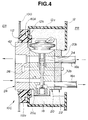
- FIG. 10C there is shown a third embodiment of the present invention, which is generally designated by numeral 10C.
- This third embodiment 10C is substantially the same as the above-mentioned first embodiment 10A of Fig. 2 except for the arrangement of a grommet put in the opening 112 of the dashboard 100.
- the grommet will be described in detail in the following, and parts substantially the same as those of the first embodiment 10A of Fig. 2 are designated by the same numerals,
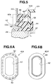
- a grommet 40A employed in the third embodiment has a portion engaged with the valve holding swelled portion 12a of the housing 12, and as is seen from Figs. 6A and 6B, the grommet 40A is shaped to have an elliptic cross section.
- the opening 112 of the dashboard 100 is shaped elliptic and has an elliptic flange 112a projected from a peripheral portion thereof toward the swelled portion 12a, and the swelled portion 12a is formed at its leading end with an inwardly extending elliptic wall 12b.
- the grommet 40A is shown in Figs. 5 to 7. As is clearly seen from Fig. 6A, 6B and 7, the grommet 40A is shaped into an elliptic cylinder.
- the grommet 40A is constructed of EPDM (ethylene propylene dien monomer) having a density greater than 0.28g/cm3, preferably 0.5g/cm3.
- the grommet 40A has an elliptic center bore 42 which extends axially.
- a first groove 44 is provided around one axial end portion of a body of the grommet 40A, which has a depth in a direction perpendicular to the axis of the grommet 40A.
- a second groove 46 is provided around the other axial end portion of the body of the grommet 40A, which has a depth in a direction parallel to the axis of the grommet 40A and faces leftward in the drawing.
- a third groove 48 is provided around an axially middle swelled portion 40a of the body of the grommet 40A, which has a depth in a direction parallel to the axis of the grommet 40A and faces rightward in the drawing.
- the third groove 48 has a trapezoidal cross section.
- the axially middle swelled portion 40a has an extension 40b which projects leftward, as viewed in Fig. 7, in a manner to surround the second groove 46 as shown.
- a plurality of openings 50 are formed in the extension 49b, which extend to the third groove 48.
- the first groove 44 receives a leading end of the wall 12b of the swelled portion 12a of the cooler unit housing 12.
- the first groove 44 is so sized as to allow the leading end of the wall 12b to compress the grommet 40A at a compression ratio smaller than 30%.
- the second groove 46 receives the flange 112a of the opening 112 of the dashboard 100.
- the extension 40b of the grommet 40A is so sized as to compress the grommet 40A (viz., a portion defined between the dashboard 100 and the wall 12b) at a compression ratio between 5% to 60%, preferably between 10% to 50%.
- an offset portion "H" is provided between an edge of the second pipe joint 24 and an axial end of the grommet 40A. The length of the offset portion "H" is greater than 2mm, preferably 5mm.
- the clearance between the dashboard 100 and the swelled portion 12a of the cooler unit housing 12 is sealed by the grommet 40A in addition to the clearance between the dashboard 100 and the second pipe joint 24, the effect of blocking the noise from transmitting from the engine room ER to the passenger room PR is much assured.
- the elasticity of the grommet 40A in the axial direction can be easily adjusted to a desired degree.
- FIG. 8 there is shown another grommet 40B which can be used in the third embodiment 10C of the present invention. Since the grommet 40B is similar to the above-mentioned grommet 40A, only portions different from those of the grommet 40A will be described in the following.
- the first groove 44' is constructed to have a depth in a direction parallel to the axis of the grommet 40B.
- the elliptic wall 12b of the cooler unit housing 12 thus has a flange 12c which is to be received in the first groove 44'.
- FIG. 9 there is shown still another grommet 40C which can be used also in the third embodiment of the present invention. Since the grommet 40C is similar to the above-mentioned grommet 40A, only portions different from those of the grommet 40A will be described in the following.
- the center bore 42' is conical in shape and the first and second grooves 44'' and 46' have each a triangular cross section.
- grommet 40D which can be used also in the third embodiment of the present invention. Since the grommet 40D is similar to the above-mentioned grommet 40A, only portions different from those of the grommet 40A will be described in the following.
- the center bore 42'' is tapered at one axial end 42''a and is formed at the other axial end with a lip 42''b.
- the third groove 48' has a rectangular cross section.
Landscapes
- Engineering & Computer Science (AREA)
- Physics & Mathematics (AREA)
- Mechanical Engineering (AREA)
- Thermal Sciences (AREA)
- General Engineering & Computer Science (AREA)
- Air-Conditioning For Vehicles (AREA)
Applications Claiming Priority (6)
| Application Number | Priority Date | Filing Date | Title |
|---|---|---|---|
| JP1993068696U JP2607788Y2 (ja) | 1993-12-22 | 1993-12-22 | 自動車用空気調和装置の配管構造 |
| JP68696/93U | 1993-12-22 | ||
| JP6869693U | 1993-12-22 | ||
| JP228264/94 | 1994-09-22 | ||
| JP22826494A JP3155668B2 (ja) | 1994-09-22 | 1994-09-22 | 自動車用配管のシール構造 |
| JP22826494 | 1994-09-22 |
Publications (2)
| Publication Number | Publication Date |
|---|---|
| EP0659600A1 true EP0659600A1 (fr) | 1995-06-28 |
| EP0659600B1 EP0659600B1 (fr) | 1999-08-04 |
Family
ID=26409898
Family Applications (1)
| Application Number | Title | Priority Date | Filing Date |
|---|---|---|---|
| EP94120301A Expired - Lifetime EP0659600B1 (fr) | 1993-12-22 | 1994-12-21 | Dispositif des tuyaux d'une installation de climatisation sur un véhicule automobile |
Country Status (3)
| Country | Link |
|---|---|
| US (1) | US5555739A (fr) |
| EP (1) | EP0659600B1 (fr) |
| DE (1) | DE69419884T2 (fr) |
Cited By (10)
| Publication number | Priority date | Publication date | Assignee | Title |
|---|---|---|---|---|
| EP0762063A1 (fr) * | 1995-09-01 | 1997-03-12 | Fujikoki Corporation | Détendeur thermostatique et installation de conditionnement d'air pour véhicules muni d'une telle soupape |
| EP0787607A3 (fr) * | 1995-09-08 | 1998-07-01 | Trinova GmbH | Dispositif d'amortissement du son |
| EP0867669A3 (fr) * | 1997-03-27 | 1998-10-14 | Fujikoki Corporation | Soupape de détente |
| US5957376A (en) * | 1996-10-11 | 1999-09-28 | Fujikori Corporation | Expansion valve |
| US6206294B1 (en) | 1996-09-12 | 2001-03-27 | Fujikoki Corporation | Expansion valve |
| US6848624B2 (en) | 2002-10-18 | 2005-02-01 | Parker-Hannifin Corporation | Refrigeration expansion valve with thermal mass power element |
| FR2907092A1 (fr) * | 2006-10-17 | 2008-04-18 | Renault Sas | Dispositif de montage etanche d'un sous-ensemble d'appareil de climatisation dans une ouverture d'une paroi d'un vehicule automobile. |
| EP2565065A4 (fr) * | 2010-04-26 | 2014-02-26 | Toyota Motor Co Ltd | Dispositif de conditionnement de l'air pour véhicules |
| EP3000632A1 (fr) * | 2014-09-25 | 2016-03-30 | Valeo Klimasysteme GmbH | Joint d'étanchéité de module de système de climatisation de véhicule et ensemble de joint d'étanchéité de module de système de climatisation de véhicule |
| WO2022030895A1 (fr) * | 2020-08-03 | 2022-02-10 | 한온시스템 주식회사 | Bride, tuyau et structure de bride |
Families Citing this family (23)
| Publication number | Priority date | Publication date | Assignee | Title |
|---|---|---|---|---|
| JPH09300950A (ja) * | 1996-05-08 | 1997-11-25 | Denso Corp | 自動車用空調装置 |
| JPH11287536A (ja) * | 1998-04-02 | 1999-10-19 | Fujikoki Corp | 膨張弁 |
| US6062484A (en) * | 1998-05-20 | 2000-05-16 | Eaton Corporation | Modular thermal expansion valve and cartridge therefor |
| US6481208B1 (en) * | 2001-10-01 | 2002-11-19 | Holtec International | External steam dump |
| CN1311995C (zh) * | 2001-10-23 | 2007-04-25 | 日本空调系统股份有限公司 | 车辆用空调装置 |
| JP3593086B2 (ja) * | 2001-10-23 | 2004-11-24 | 株式会社日本クライメイトシステムズ | 車両用空調装置 |
| JP4462807B2 (ja) * | 2002-03-15 | 2010-05-12 | 株式会社不二工機 | 膨張弁又は膨張弁用ケース |
| JP2004053060A (ja) * | 2002-07-17 | 2004-02-19 | Fuji Koki Corp | 膨張弁 |
| JP2004053182A (ja) * | 2002-07-23 | 2004-02-19 | Fuji Koki Corp | 膨張弁 |
| US6868684B2 (en) * | 2002-12-17 | 2005-03-22 | Parker-Hannifin Corporation | Block valve with integral refrigerant lines |
| US7089761B2 (en) * | 2004-01-08 | 2006-08-15 | Parker-Hannifin Corporation | Expansion valve with mounting bracket |
| JP4403980B2 (ja) * | 2004-04-14 | 2010-01-27 | 株式会社デンソー | 車両用空調装置の配管シール構造 |
| JP4466448B2 (ja) * | 2005-04-18 | 2010-05-26 | 株式会社デンソー | 車両用空調装置 |
| JP4807210B2 (ja) * | 2005-12-27 | 2011-11-02 | 株式会社デンソー | シール装置およびシール構造 |
| ES2280143B1 (es) * | 2006-02-21 | 2008-05-16 | Bsh Electrodomesticos España, S.A. | Dispositivo para el tendido de conductos. |
| JP2008175417A (ja) * | 2007-01-16 | 2008-07-31 | Calsonic Kansei Corp | 膨張弁 |
| KR101437941B1 (ko) | 2008-08-22 | 2014-09-05 | 한라비스테온공조 주식회사 | 차량용 공조시스템 |
| DE102009056043A1 (de) * | 2009-11-27 | 2011-06-01 | GM Global Technology Operations LLC, ( n. d. Ges. d. Staates Delaware ), Detroit | Dichtungsanordnung für die Kraftfahrzeugstirnwand |
| JP6067975B2 (ja) * | 2012-03-01 | 2017-01-25 | 株式会社日本クライメイトシステムズ | 車両用空調装置 |
| JP5891968B2 (ja) * | 2012-06-22 | 2016-03-23 | 株式会社デンソー | 減圧装置 |
| CN103644412A (zh) * | 2013-11-28 | 2014-03-19 | 博耐尔汽车电气系统有限公司 | 一种汽车空调加热器进出水管密封件 |
| US9844997B2 (en) * | 2014-05-15 | 2017-12-19 | Hanon Systems | Air conditioner for vehicle |
| WO2017077769A1 (fr) * | 2015-11-06 | 2017-05-11 | 株式会社日立製作所 | Structure de vanne, et dispositif hydraulique, machine à fluide, et machine, chacun la comportant |
Citations (2)
| Publication number | Priority date | Publication date | Assignee | Title |
|---|---|---|---|---|
| DE3339214A1 (de) * | 1982-11-03 | 1984-05-03 | The Singer Co., Stamford, Conn. | Thermostatisches expansionsventil fuer flanschmontage |
| US5165251A (en) * | 1990-04-17 | 1992-11-24 | Calsonic Corporation | Coupler for pipe of cooler unit |
Family Cites Families (5)
| Publication number | Priority date | Publication date | Assignee | Title |
|---|---|---|---|---|
| US2296997A (en) * | 1940-08-03 | 1942-09-29 | Marion F Knoy | Condensate disposal means |
| US2525868A (en) * | 1948-11-17 | 1950-10-17 | Sebastien S Corhanidis | Refrigerating system having a detachable unit |
| US2655009A (en) * | 1949-11-17 | 1953-10-13 | Wilford C Thompson | Refrigeration system for vehicles |
| US3685311A (en) * | 1972-06-01 | 1972-08-22 | Gen Motors Corp | Evaporator-blower package |
| JPS6396918A (ja) * | 1986-10-14 | 1988-04-27 | Matsushita Electric Ind Co Ltd | パタ−ン形成方法 |
-
1994
- 1994-12-21 EP EP94120301A patent/EP0659600B1/fr not_active Expired - Lifetime
- 1994-12-21 DE DE69419884T patent/DE69419884T2/de not_active Expired - Fee Related
- 1994-12-22 US US08/361,840 patent/US5555739A/en not_active Expired - Lifetime
Patent Citations (2)
| Publication number | Priority date | Publication date | Assignee | Title |
|---|---|---|---|---|
| DE3339214A1 (de) * | 1982-11-03 | 1984-05-03 | The Singer Co., Stamford, Conn. | Thermostatisches expansionsventil fuer flanschmontage |
| US5165251A (en) * | 1990-04-17 | 1992-11-24 | Calsonic Corporation | Coupler for pipe of cooler unit |
Cited By (16)
| Publication number | Priority date | Publication date | Assignee | Title |
|---|---|---|---|---|
| CN1076457C (zh) * | 1995-09-01 | 2001-12-19 | 株式会社不二工机 | 温度膨胀阀 |
| EP0762063A1 (fr) * | 1995-09-01 | 1997-03-12 | Fujikoki Corporation | Détendeur thermostatique et installation de conditionnement d'air pour véhicules muni d'une telle soupape |
| EP0787607A3 (fr) * | 1995-09-08 | 1998-07-01 | Trinova GmbH | Dispositif d'amortissement du son |
| US5955707A (en) * | 1995-09-08 | 1999-09-21 | Trinova Gmbh | Sound damping means for air conditioning system |
| US6206294B1 (en) | 1996-09-12 | 2001-03-27 | Fujikoki Corporation | Expansion valve |
| US5957376A (en) * | 1996-10-11 | 1999-09-28 | Fujikori Corporation | Expansion valve |
| US6189800B1 (en) * | 1996-10-11 | 2001-02-20 | Fujikoki Corporation | Expansion valve |
| US6092733A (en) * | 1997-03-27 | 2000-07-25 | Fujikoki Corporation | Expansion valve |
| EP0867669A3 (fr) * | 1997-03-27 | 1998-10-14 | Fujikoki Corporation | Soupape de détente |
| US6848624B2 (en) | 2002-10-18 | 2005-02-01 | Parker-Hannifin Corporation | Refrigeration expansion valve with thermal mass power element |
| FR2907092A1 (fr) * | 2006-10-17 | 2008-04-18 | Renault Sas | Dispositif de montage etanche d'un sous-ensemble d'appareil de climatisation dans une ouverture d'une paroi d'un vehicule automobile. |
| WO2008047031A1 (fr) * | 2006-10-17 | 2008-04-24 | Renault S.A.S. | Dispositif de montage etanche d'un sous-ensemble d'appareil de climatisation dans une ouverture d'une paroi d'un vehicule automobile |
| EP2565065A4 (fr) * | 2010-04-26 | 2014-02-26 | Toyota Motor Co Ltd | Dispositif de conditionnement de l'air pour véhicules |
| EP3000632A1 (fr) * | 2014-09-25 | 2016-03-30 | Valeo Klimasysteme GmbH | Joint d'étanchéité de module de système de climatisation de véhicule et ensemble de joint d'étanchéité de module de système de climatisation de véhicule |
| WO2022030895A1 (fr) * | 2020-08-03 | 2022-02-10 | 한온시스템 주식회사 | Bride, tuyau et structure de bride |
| US12233689B2 (en) | 2020-08-03 | 2025-02-25 | Hanon Systems | Flange, and pipe and flange structure |
Also Published As
| Publication number | Publication date |
|---|---|
| US5555739A (en) | 1996-09-17 |
| EP0659600B1 (fr) | 1999-08-04 |
| DE69419884D1 (de) | 1999-09-09 |
| DE69419884T2 (de) | 1999-12-02 |
Similar Documents
| Publication | Publication Date | Title |
|---|---|---|
| US5555739A (en) | Piping arrangement of automotive air conditioner | |
| US6443502B1 (en) | Leakage restriction device for refrigeration cycle | |
| US5556138A (en) | Pipe connecting device | |
| US5545860A (en) | Discharge muffler for an automotive compressor and method for making same | |
| US4781362A (en) | Hydraulically damping elastic bearing | |
| US7753413B2 (en) | Vapour-compression type refrigerating machine and double pipe structure and double pipe joint structure preferably used therefor | |
| US4802698A (en) | Joint means having flanges | |
| US5955707A (en) | Sound damping means for air conditioning system | |
| US5957415A (en) | Device for fixing at least one fluid pipe to a support | |
| US5521340A (en) | Tuned tube muffler for an automotive vehicle | |
| US4796896A (en) | Multi-stage elastomeric seal with retainer | |
| US5165251A (en) | Coupler for pipe of cooler unit | |
| US20050166584A1 (en) | Gasket and heat shield assembly for a flanged joint | |
| JPH1191338A (ja) | 車両用空気調和装置 | |
| JPH01289714A (ja) | 自動車用配管接続構造 | |
| JPH1086651A (ja) | 自動車用配管のシール構造 | |
| US5435699A (en) | Accumulator for air conditioning system | |
| JPH0891044A (ja) | 自動車用配管のシール構造 | |
| JPH07293775A (ja) | 配管接続継手 | |
| JPH0988918A (ja) | クランプ及びクランプ構体 | |
| US20020171206A1 (en) | High temperature coating of exhaust components | |
| KR19980081304A (ko) | 공기조절장치의 배관접속부의 시일구조 | |
| JPH0755434Y2 (ja) | パイプの接続構造 | |
| JPH0329668Y2 (fr) | ||
| JP2510274Y2 (ja) | 自動車用空気調和装置の配管用継手 |
Legal Events
| Date | Code | Title | Description |
|---|---|---|---|
| PUAI | Public reference made under article 153(3) epc to a published international application that has entered the european phase |
Free format text: ORIGINAL CODE: 0009012 |
|
| 17P | Request for examination filed |
Effective date: 19941221 |
|
| AK | Designated contracting states |
Kind code of ref document: A1 Designated state(s): DE FR GB |
|
| 17Q | First examination report despatched |
Effective date: 19961014 |
|
| GRAG | Despatch of communication of intention to grant |
Free format text: ORIGINAL CODE: EPIDOS AGRA |
|
| GRAG | Despatch of communication of intention to grant |
Free format text: ORIGINAL CODE: EPIDOS AGRA |
|
| GRAH | Despatch of communication of intention to grant a patent |
Free format text: ORIGINAL CODE: EPIDOS IGRA |
|
| GRAH | Despatch of communication of intention to grant a patent |
Free format text: ORIGINAL CODE: EPIDOS IGRA |
|
| GRAA | (expected) grant |
Free format text: ORIGINAL CODE: 0009210 |
|
| AK | Designated contracting states |
Kind code of ref document: B1 Designated state(s): DE FR GB |
|
| REF | Corresponds to: |
Ref document number: 69419884 Country of ref document: DE Date of ref document: 19990909 |
|
| ET | Fr: translation filed | ||
| PLBE | No opposition filed within time limit |
Free format text: ORIGINAL CODE: 0009261 |
|
| STAA | Information on the status of an ep patent application or granted ep patent |
Free format text: STATUS: NO OPPOSITION FILED WITHIN TIME LIMIT |
|
| 26N | No opposition filed | ||
| REG | Reference to a national code |
Ref country code: GB Ref legal event code: IF02 |
|
| PGFP | Annual fee paid to national office [announced via postgrant information from national office to epo] |
Ref country code: DE Payment date: 20060120 Year of fee payment: 12 |
|
| PG25 | Lapsed in a contracting state [announced via postgrant information from national office to epo] |
Ref country code: DE Free format text: LAPSE BECAUSE OF NON-PAYMENT OF DUE FEES Effective date: 20070703 |
|
| PGFP | Annual fee paid to national office [announced via postgrant information from national office to epo] |
Ref country code: FR Payment date: 20081212 Year of fee payment: 15 |
|
| PGFP | Annual fee paid to national office [announced via postgrant information from national office to epo] |
Ref country code: GB Payment date: 20081217 Year of fee payment: 15 |
|
| GBPC | Gb: european patent ceased through non-payment of renewal fee |
Effective date: 20091221 |
|
| REG | Reference to a national code |
Ref country code: FR Ref legal event code: ST Effective date: 20100831 |
|
| PG25 | Lapsed in a contracting state [announced via postgrant information from national office to epo] |
Ref country code: FR Free format text: LAPSE BECAUSE OF NON-PAYMENT OF DUE FEES Effective date: 20091231 |
|
| PG25 | Lapsed in a contracting state [announced via postgrant information from national office to epo] |
Ref country code: GB Free format text: LAPSE BECAUSE OF NON-PAYMENT OF DUE FEES Effective date: 20091221 |