EP0659665A1 - Dispositif pour l'alimentation en continu d'articles d'un convoyeur principal vers des canaux intermédiaires, disposés obliquement par rapport au convoyeur principal - Google Patents
Dispositif pour l'alimentation en continu d'articles d'un convoyeur principal vers des canaux intermédiaires, disposés obliquement par rapport au convoyeur principal Download PDFInfo
- Publication number
- EP0659665A1 EP0659665A1 EP94830585A EP94830585A EP0659665A1 EP 0659665 A1 EP0659665 A1 EP 0659665A1 EP 94830585 A EP94830585 A EP 94830585A EP 94830585 A EP94830585 A EP 94830585A EP 0659665 A1 EP0659665 A1 EP 0659665A1
- Authority
- EP
- European Patent Office
- Prior art keywords
- articles
- conveying line
- main
- line
- raising means
- Prior art date
- Legal status (The legal status is an assumption and is not a legal conclusion. Google has not performed a legal analysis and makes no representation as to the accuracy of the status listed.)
- Withdrawn
Links
- 238000011144 upstream manufacturing Methods 0.000 claims abstract description 3
- 230000008878 coupling Effects 0.000 description 1
- 238000010168 coupling process Methods 0.000 description 1
- 238000005859 coupling reaction Methods 0.000 description 1
- 230000009849 deactivation Effects 0.000 description 1
- 238000004519 manufacturing process Methods 0.000 description 1
Images


Classifications
-
- B—PERFORMING OPERATIONS; TRANSPORTING
- B65—CONVEYING; PACKING; STORING; HANDLING THIN OR FILAMENTARY MATERIAL
- B65G—TRANSPORT OR STORAGE DEVICES, e.g. CONVEYORS FOR LOADING OR TIPPING, SHOP CONVEYOR SYSTEMS OR PNEUMATIC TUBE CONVEYORS
- B65G47/00—Article or material-handling devices associated with conveyors; Methods employing such devices
- B65G47/74—Feeding, transfer, or discharging devices of particular kinds or types
- B65G47/82—Rotary or reciprocating members for direct action on articles or materials, e.g. pushers, rakes, shovels
Definitions
- the present invention relates to transferring various articles to outlet ways provided along a main conveying line.
- Such auxiliary conveying lines are usually arranged at a certain angle with respect to the main line, in particular perpendicular thereto.
- the object of the present invention is to propose a device that allows for a continuous selective transferring of articles to one or more intermediate outlets placed along a main conveying line of these articles.
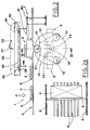
- the reference numeral 1 indicates the main line conveying the articles 2.
- the conveying line 1 includes a slide surface 3 for the articles 2, that is formed, in correspondence with the operative zone of the subject device, by a plurality of longitudinal plates 4 arranged side by side.
- the cross bars 5 are aimed at pushing on the back side of articles 2, or of groups of articles transversely flanked with each other, to be conveyed.
- the upper active run 8a of the conveying line 8 is located over the slide surface 3 of the main line 1, at a suitable distance therefrom, so as to allow the articles conveyed on the line 1 to pass under it.
- the device for taking over the articles 2 has, upstream of the outlet way 7, a plurality of raising means 9 moved by a rotary drum means 10.
- the drum means 10 is situated under the slide surface 3 of the main conveying line 1 and rotates around a horizontal axis transversal to the line 1.
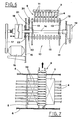
- the raising means 9, e.g. three as in the illustrated case, are arranged regularly along the periphery of the rotary drum 10, and have the form of a comb, constituted by a plurality of prongs 11, carried side by side by a bar 12.
- the bar 12 is rotatably mounted between a pair of circular heads 13 of the rotary drum 10.
- the circular heads 13 are joined to a driving shaft 14 of the rotary drum 10, rotatably supported by a pair of side walls 15 of the device ( Figure 6).
- the driving shaft 14 of the rotary drum 10 can be driven to rotate either by driving means 16, through a flexible link 17, or, preferably, by not illustrated means, interlocked with the main driving of the machine in which the present device is inserted.
- a front coupling clutch 18 is mounted on the driving shaft 14 to allow deactivation of the taking over device.
- the driving shaft 14 is also equipped with braking means 19 for stopping the device.
- each bar 12 of the raising means 9, protruding from the circular head 13 of the rotary drum 10, has e toothed wheel 20 fastened thereto.
- the toothed wheels 20 are rotated by a toothed belt 21 that are trained around a pair of idler pulleys 22, carried by the said head 13, and a pinion 23, fixed to the adjacent side wall 15.
- the pinion 23 and the driving shaft 14 are coaxial.
- the pinion 23 and the toothed wheels 20 are equal in diameter.
- the idler pulleys 22 are situated symmetrically at both side of the pinion 23.
- the raising means 9, carried by the rotary drum 10, move while keeping the loading surface delimited by the prongs 11 with constant horizontal attitude.
- Pushing means 24, made to move by a chain 25 located over the main conveying line 1, are aimed at cooperating with the raising means 9.
- the chain 25 is trained around a pair of sprockets 26.
- the speed with which the said chain 25 is operated is suitably bigger than the advancement speed of the articles 2 along the main line 1.
- the pushers 24 are hinged to the chain 25 about respective pivot 27, and bear rollers 28, aimed at running along a longitudinal guide 29 in correspondence with the active run of the same chain 25.
- the terminal part 30 of the guide 29 is suitably inclined and makes the pushers 24 to rotate, in a direction contrary to the pusher motion, when the articles 2 are released.
- the flat 31 is formed by a plurality of longitudinal plates 32, arranged side by side, correspondent to the plates 4 that form the slide surface 3 of the main line 1.
- Each of the comb-shaped raising means 9 is brought in turn, by the rotation of the drum 10, to cross the slide surface 3 of the main line 1 so as to raise a respective article 2 from this surface 3.
- prongs 11 of the raising means 9 are staggered with respect to the plates 4 of the slide surface 3, so that, in the raising phase, they insert between these plates 4, as it is seen in Figure 5.
- the raising means goes first up and then down, as a result of the trajectory imposed to the bar 12 by the rotary drum 10.
- the article 2, raised by the raising means 9, is pushed by a relative pusher 24, guided along the guide 29 and operated with the speed suitably bigger than the advancement speed of the main line 1.
- the rotary drum 10 is disconnected and stopped, so as to avoid the raising of the articles 2.
- Suitable sensors define the position in which the rotary drum 10 is stopped so that the raising means 9 do not interfere with the slide surface 3 of the main line 1.
- the clutch 18 allows to keep the proper phase relation for rotation of the drum 10, movements of the conveying line 1 and movements of the pushers 24.
- the described device for taking over the articles allows for selective taking over thereof from the main line and for transferring them to a suitable outlet way.
- the articles are selectively taken over in a continuous way, without stopping or slowing down or moving the articles away from the conveying path.
Landscapes
- Engineering & Computer Science (AREA)
- Mechanical Engineering (AREA)
- Specific Conveyance Elements (AREA)
- Sorting Of Articles (AREA)
- Image Analysis (AREA)
- Special Conveying (AREA)
Applications Claiming Priority (2)
| Application Number | Priority Date | Filing Date | Title |
|---|---|---|---|
| ITBO930522 | 1993-12-23 | ||
| IT93BO000522A IT1264299B1 (it) | 1993-12-23 | 1993-12-23 | Dispositivo per l'estrazione in continuo di articoli da una linea principale a uscite intermedie poste angolarmente rispetto a tale |
Publications (1)
| Publication Number | Publication Date |
|---|---|
| EP0659665A1 true EP0659665A1 (fr) | 1995-06-28 |
Family
ID=11339377
Family Applications (1)
| Application Number | Title | Priority Date | Filing Date |
|---|---|---|---|
| EP94830585A Withdrawn EP0659665A1 (fr) | 1993-12-23 | 1994-12-23 | Dispositif pour l'alimentation en continu d'articles d'un convoyeur principal vers des canaux intermédiaires, disposés obliquement par rapport au convoyeur principal |
Country Status (3)
| Country | Link |
|---|---|
| US (1) | US5529167A (fr) |
| EP (1) | EP0659665A1 (fr) |
| IT (1) | IT1264299B1 (fr) |
Cited By (7)
| Publication number | Priority date | Publication date | Assignee | Title |
|---|---|---|---|---|
| WO1998049083A3 (fr) * | 1997-04-30 | 1999-02-11 | Siemens Ag | Dispositif pour le transfert de colis entre deux convoyeurs |
| EP1407991A1 (fr) * | 2002-10-11 | 2004-04-14 | Ferag AG | Dispositif pour déplacer des articles se trouvant sur un convoyeur |
| EP2070847A1 (fr) * | 2007-12-13 | 2009-06-17 | ETA SA Manufacture Horlogère Suisse | Aiguillage pour transporteur |
| CN106743446A (zh) * | 2017-01-19 | 2017-05-31 | 桐乡市佳顺自动化机械有限公司 | 一种磁性材料排列输送设备 |
| CN106144570B (zh) * | 2016-08-25 | 2018-08-03 | 莆田烟草物流有限公司 | 一种防溜烟半自动分拣拨烟装置 |
| WO2020094318A1 (fr) * | 2018-11-08 | 2020-05-14 | Krones Ag | Dispositif de regroupement de contenants |
| CN118976722A (zh) * | 2024-10-22 | 2024-11-19 | 常州三恒电器有限公司 | 一种互感器自动测试分选机 |
Families Citing this family (9)
| Publication number | Priority date | Publication date | Assignee | Title |
|---|---|---|---|---|
| US6349815B1 (en) * | 2000-02-14 | 2002-02-26 | Peters Machinery Corporation | In-line stacker machine for stacking cookies |
| NL1015030C2 (nl) * | 2000-04-14 | 2001-10-16 | Fico Bv | Werkwijze en inrichting voor transport van elektronische componenten. |
| JP2002120812A (ja) * | 2000-10-16 | 2002-04-23 | Ishida Co Ltd | 箱詰めシステムにおける製品振り分け機構 |
| ITBO20020049A1 (it) * | 2002-01-31 | 2003-07-31 | Casmatic Spa | Apparato a passo variabile , per l'alimentazione per spinta ed in fase di prodotti ad una successiva stazione di lavoro |
| SE527834C2 (sv) * | 2004-11-10 | 2006-06-13 | Norden Pac Dev Ab | Anordning och förfarande för kartoneringsmaskin |
| DE102006045107B4 (de) * | 2006-09-21 | 2015-03-12 | Optima Nonwovens Gmbh | Reversierende Vorschubeinrichtung zum taktweisen linearen Vorschieben von Gutstapeln über eine Transportstrecke |
| ATE533710T1 (de) * | 2008-06-13 | 2011-12-15 | Advanced Nuclear Fuels Gmbh | Übertragungs- und isolierungsvorrichtung |
| EP3009359B1 (fr) * | 2014-10-13 | 2017-07-05 | Tetra Laval Holdings & Finance S.A. | Unité d'alimentation pour alimenter des emballages scellés de produits alimentaires versables |
| CN110510389B (zh) * | 2019-09-29 | 2024-04-12 | 深圳赛动生物自动化有限公司 | 培养瓶自动传输机构及传输方法 |
Citations (3)
| Publication number | Priority date | Publication date | Assignee | Title |
|---|---|---|---|---|
| US4917229A (en) * | 1988-12-21 | 1990-04-17 | Apv Douglas Machine Corporation | Method and apparatus for stacking products |
| DE4105273A1 (de) * | 1990-02-21 | 1991-08-22 | Baumer Srl | Vorrichtung zum stapeln von packungseinheiten |
| EP0521428A1 (fr) * | 1991-07-04 | 1993-01-07 | CAVANNA S.p.A. | Dispositif pour former des piles d'objets, notamment pour installations d'emballage automatiques |
Family Cites Families (8)
| Publication number | Priority date | Publication date | Assignee | Title |
|---|---|---|---|---|
| GB1032417A (en) * | 1961-11-03 | 1966-06-08 | Forgrove Mach | Improvements in or relating to article feeding apparatus |
| US4226176A (en) * | 1979-05-01 | 1980-10-07 | Giannino Macchi | Bread toaster |
| US4505373A (en) * | 1982-07-01 | 1985-03-19 | Diamond Automations, Inc. | Egg transfer system |
| ES2028138T3 (es) * | 1987-02-16 | 1992-07-01 | Gebr. Bindler Maschinenfabrik Gmbh & Co. Kg | Dispositivo de transporte y manipulacion para moldes rellenables con masa fundible, que se endurece, como chocolate. |
| DE3715570A1 (de) * | 1987-05-09 | 1988-12-01 | Benz & Hilgers Gmbh | Vorrichtung zum transport von gegenstaenden, insbesondere rechteckigen verpackungen |
| US5238100A (en) * | 1991-06-13 | 1993-08-24 | Ford Motor Company | Method and apparatus for handling glass sheets |
| DE4334479A1 (de) * | 1992-11-06 | 1994-05-11 | Focke & Co | Vorrichtung zum Transport von Zigaretten-Packungen |
| US5291986A (en) * | 1992-11-16 | 1994-03-08 | Aetna Life Insurance Company | Printer exit retriever and conveyor |
-
1993
- 1993-12-23 IT IT93BO000522A patent/IT1264299B1/it active IP Right Grant
-
1994
- 1994-12-20 US US08/359,438 patent/US5529167A/en not_active Expired - Fee Related
- 1994-12-23 EP EP94830585A patent/EP0659665A1/fr not_active Withdrawn
Patent Citations (3)
| Publication number | Priority date | Publication date | Assignee | Title |
|---|---|---|---|---|
| US4917229A (en) * | 1988-12-21 | 1990-04-17 | Apv Douglas Machine Corporation | Method and apparatus for stacking products |
| DE4105273A1 (de) * | 1990-02-21 | 1991-08-22 | Baumer Srl | Vorrichtung zum stapeln von packungseinheiten |
| EP0521428A1 (fr) * | 1991-07-04 | 1993-01-07 | CAVANNA S.p.A. | Dispositif pour former des piles d'objets, notamment pour installations d'emballage automatiques |
Cited By (9)
| Publication number | Priority date | Publication date | Assignee | Title |
|---|---|---|---|---|
| WO1998049083A3 (fr) * | 1997-04-30 | 1999-02-11 | Siemens Ag | Dispositif pour le transfert de colis entre deux convoyeurs |
| EP1407991A1 (fr) * | 2002-10-11 | 2004-04-14 | Ferag AG | Dispositif pour déplacer des articles se trouvant sur un convoyeur |
| EP2070847A1 (fr) * | 2007-12-13 | 2009-06-17 | ETA SA Manufacture Horlogère Suisse | Aiguillage pour transporteur |
| CN106144570B (zh) * | 2016-08-25 | 2018-08-03 | 莆田烟草物流有限公司 | 一种防溜烟半自动分拣拨烟装置 |
| CN106743446A (zh) * | 2017-01-19 | 2017-05-31 | 桐乡市佳顺自动化机械有限公司 | 一种磁性材料排列输送设备 |
| CN106743446B (zh) * | 2017-01-19 | 2022-06-17 | 桐乡市佳顺自动化机械有限公司 | 一种磁性材料排列输送设备 |
| WO2020094318A1 (fr) * | 2018-11-08 | 2020-05-14 | Krones Ag | Dispositif de regroupement de contenants |
| US11492207B2 (en) | 2018-11-08 | 2022-11-08 | Krones Ag | Device for grouping containers |
| CN118976722A (zh) * | 2024-10-22 | 2024-11-19 | 常州三恒电器有限公司 | 一种互感器自动测试分选机 |
Also Published As
| Publication number | Publication date |
|---|---|
| US5529167A (en) | 1996-06-25 |
| ITBO930522A0 (it) | 1993-12-23 |
| IT1264299B1 (it) | 1996-09-23 |
| ITBO930522A1 (it) | 1995-06-23 |
Similar Documents
| Publication | Publication Date | Title |
|---|---|---|
| US5529167A (en) | Device for continuously feeding articles from a main conveying line to intermediate outlet ways arranged angularly with respect to the main line | |
| CN111655585B (zh) | 具有纸箱翻转站的连续运动包装机 | |
| US4676361A (en) | Troughing conveyors for carton or bag orienting and conveying | |
| US4364465A (en) | Collating conveyor system | |
| US4646908A (en) | Apparatus for stacking packages in particular for wrapping installations using a strip of heat-shrinkable material | |
| DK163656B (da) | Fremgangsmaade og apparat til samling af foldede trykte ark | |
| EP0767126B1 (fr) | Dispositif de déviation pour le transport de produits, en particulier de produits graphiques ou d'édition | |
| GB2241216A (en) | Stacking apparatus | |
| US5450941A (en) | Apparatus for separating, conveying and grouping flat items | |
| US6964147B2 (en) | Operating method for a packaging machine of the “sleeve” type, packaging machine for implementing the said method, and package produced by the said method | |
| EP1533257B1 (fr) | Station pour raccorder une machine d'emballage, en particulier une machine de fabrication de blisters, à une ligne d'alimentation d'une machine d'encaissage | |
| EP0608103B1 (fr) | Système de transport à poussoirs pour cartons en machines d'emballage | |
| US5309697A (en) | Chewing gum packaging machine | |
| EP0825118B1 (fr) | Procédé pour former des groupes de paquets | |
| EP0447123B1 (fr) | Alimentation et mécanisme de groupement dans une machine d'emballage | |
| JPH09278165A (ja) | 整列装置 | |
| AU4887899A (en) | Method to produce printed articles by inserting at least one part-product into a main product and device to carry out the method | |
| EP1003675A1 (fr) | Mecanisme de transfert | |
| US4244460A (en) | Process and equipment to form modules of biscuits or other like products | |
| US6705607B2 (en) | Device for transporting printed products | |
| US4449624A (en) | Device for conveying and redistributing objects | |
| EP0780329B1 (fr) | Dispositif de transport d'articles | |
| GB2051552A (en) | Apparatus for conveying rod- like articles | |
| EP0909724B1 (fr) | Station pour retirer et évacuer des produits arrangés en lignes sur un transporteur à bande | |
| DE3415136C2 (fr) |
Legal Events
| Date | Code | Title | Description |
|---|---|---|---|
| PUAI | Public reference made under article 153(3) epc to a published international application that has entered the european phase |
Free format text: ORIGINAL CODE: 0009012 |
|
| AK | Designated contracting states |
Kind code of ref document: A1 Designated state(s): DE ES FR GB |
|
| 17P | Request for examination filed |
Effective date: 19951113 |
|
| 17Q | First examination report despatched |
Effective date: 19961108 |
|
| GRAG | Despatch of communication of intention to grant |
Free format text: ORIGINAL CODE: EPIDOS AGRA |
|
| GRAG | Despatch of communication of intention to grant |
Free format text: ORIGINAL CODE: EPIDOS AGRA |
|
| GRAH | Despatch of communication of intention to grant a patent |
Free format text: ORIGINAL CODE: EPIDOS IGRA |
|
| STAA | Information on the status of an ep patent application or granted ep patent |
Free format text: STATUS: THE APPLICATION IS DEEMED TO BE WITHDRAWN |
|
| 18D | Application deemed to be withdrawn |
Effective date: 19980704 |