EP0780329B1 - Dispositif de transport d'articles - Google Patents
Dispositif de transport d'articles Download PDFInfo
- Publication number
- EP0780329B1 EP0780329B1 EP19960203623 EP96203623A EP0780329B1 EP 0780329 B1 EP0780329 B1 EP 0780329B1 EP 19960203623 EP19960203623 EP 19960203623 EP 96203623 A EP96203623 A EP 96203623A EP 0780329 B1 EP0780329 B1 EP 0780329B1
- Authority
- EP
- European Patent Office
- Prior art keywords
- conveyor
- slide plate
- articles
- transport
- guide
- Prior art date
- Legal status (The legal status is an assumption and is not a legal conclusion. Google has not performed a legal analysis and makes no representation as to the accuracy of the status listed.)
- Expired - Lifetime
Links
- 238000011144 upstream manufacturing Methods 0.000 claims description 6
- 238000007599 discharging Methods 0.000 claims description 4
- 238000006073 displacement reaction Methods 0.000 claims description 2
- 230000004048 modification Effects 0.000 description 3
- 238000012986 modification Methods 0.000 description 3
- 241000282472 Canis lupus familiaris Species 0.000 description 1
- 235000019504 cigarettes Nutrition 0.000 description 1
- 238000010586 diagram Methods 0.000 description 1
- 238000009877 rendering Methods 0.000 description 1
- 230000000717 retained effect Effects 0.000 description 1
Images


Classifications
-
- B—PERFORMING OPERATIONS; TRANSPORTING
- B65—CONVEYING; PACKING; STORING; HANDLING THIN OR FILAMENTARY MATERIAL
- B65G—TRANSPORT OR STORAGE DEVICES, e.g. CONVEYORS FOR LOADING OR TIPPING, SHOP CONVEYOR SYSTEMS OR PNEUMATIC TUBE CONVEYORS
- B65G47/00—Article or material-handling devices associated with conveyors; Methods employing such devices
- B65G47/74—Feeding, transfer, or discharging devices of particular kinds or types
- B65G47/84—Star-shaped wheels or devices having endless travelling belts or chains, the wheels or devices being equipped with article-engaging elements
- B65G47/841—Devices having endless travelling belts or chains equipped with article-engaging elements
-
- B—PERFORMING OPERATIONS; TRANSPORTING
- B65—CONVEYING; PACKING; STORING; HANDLING THIN OR FILAMENTARY MATERIAL
- B65G—TRANSPORT OR STORAGE DEVICES, e.g. CONVEYORS FOR LOADING OR TIPPING, SHOP CONVEYOR SYSTEMS OR PNEUMATIC TUBE CONVEYORS
- B65G47/00—Article or material-handling devices associated with conveyors; Methods employing such devices
- B65G47/22—Devices influencing the relative position or the attitude of articles during transit by conveyors
- B65G47/26—Devices influencing the relative position or the attitude of articles during transit by conveyors arranging the articles, e.g. varying spacing between individual articles
- B65G47/30—Devices influencing the relative position or the attitude of articles during transit by conveyors arranging the articles, e.g. varying spacing between individual articles during transit by a series of conveyors
- B65G47/32—Applications of transfer devices
-
- B—PERFORMING OPERATIONS; TRANSPORTING
- B65—CONVEYING; PACKING; STORING; HANDLING THIN OR FILAMENTARY MATERIAL
- B65G—TRANSPORT OR STORAGE DEVICES, e.g. CONVEYORS FOR LOADING OR TIPPING, SHOP CONVEYOR SYSTEMS OR PNEUMATIC TUBE CONVEYORS
- B65G47/00—Article or material-handling devices associated with conveyors; Methods employing such devices
- B65G47/52—Devices for transferring articles or materials between conveyors i.e. discharging or feeding devices
- B65G47/68—Devices for transferring articles or materials between conveyors i.e. discharging or feeding devices adapted to receive articles arriving in one layer from one conveyor lane and to transfer them in individual layers to more than one conveyor lane or to one broader conveyor lane, or vice versa, e.g. combining the flows of articles conveyed by more than one conveyor
- B65G47/681—Devices for transferring articles or materials between conveyors i.e. discharging or feeding devices adapted to receive articles arriving in one layer from one conveyor lane and to transfer them in individual layers to more than one conveyor lane or to one broader conveyor lane, or vice versa, e.g. combining the flows of articles conveyed by more than one conveyor from distinct, separate conveyor lanes
Definitions
- the present invention relates to apparatus for transporting articles, for example, paper packs filled with contents.
- Such apparatus include those comprising a first conveyor having one or a plurality of transport paths extending forward, a delivery device for forwardly discharging articles from the front end of each transport path of the first conveyor, and a second conveyor having a continuously drivable endless belt so disposed as to receive the articles discharged by the delivery device and extending in a direction orthogonal to the transport path or paths of the first conveyor.
- the article discharged by the delivery device tends to tumble when the belt receives the article. If the second conveyor is slowed down to avoid this, the article to be currently discharged will interfere with the article discharged in the preceding cycle, hence a limitation to the reduction in the operating speed of the second conveyor.
- An object of the present invention is to provide an article transport apparatus of the type described wherein articles can be transferred from the first conveyor to the second conveyor with good stability without tumbling the article
- the present invention provides an article transport apparatus as defined in claim 1.
- the article sent forward by the first conveyor is discharged from the first conveyor by the delivery device and then received by the fixed slide plate of the second conveyor.
- the received article is pushed forward on the slide plate by the pusher member.
- the article can be transferred from the first conveyor to the second conveyor with good stability without tumbling.
- the article transport apparatus further comprises a third conveyor continuously drivable in the same direction as the direction of movement of the pusher member and having a transport path connected to the slide plate in parallel thereto and a guide rail extending obliquely across the slide plate thereabove so as to be positioned downstream with respect to the direction of movement of the pusher member.
- the article pushed forward on the slide plate is then guided from the glide plate onto the third conveyor by the guide rail.
- Articles can therefore be transported from the first conveyor to the third conveyor without tumbling.
- the third conveyor may be connected in series with the second conveyor.
- the article is guided from the slide plate onto the third conveyor without a speed variation. This assures smooth transfer of the article from the slide plate onto the third conveyor.
- the two transport paths of the first conveyor deliver articles respectively to an upstream receiving position and a downstream receiving position on the slide plate.
- the apparatus is so adapted that when an article is delivered to the downstream receiving position, another article delivered to the upstream receiving position and being pushed by one of the pusher members is positioned between the two receiving positions. The article delivered to the downstream receiving position is then pushed forward by the article delivered to the upstream receiving position and pushed by one of the pusher members.
- GB-A-356 648 discloses a transport apparatus for coils or bundles of wire wherein by means of a chain with dogs the coils or bundles are shifted on a platform provided with a longitudinal groove accommodating hooks for picking up the coils or bundles.
- GB-2 005 211 discloses a device for transferring and combining cigarette packs comprising two parallel endless conveying belts. From said conveying belts the packs are displaced by means of rotating wheels towards a further endless belt.
- front refers to the side toward which containers advance as transported by a first conveyor 11 (the arrow A in FIG. 2), the term “rear” to the opposite side, and the terms “right” and “left,” respectively, to the right and left sides of the illustrated apparatus as it is seen from the front (the right-hand side and left-hand side of FIG. 2).
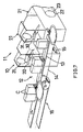
- FIG. 1 shows the front end portion of the first conveyor 11 and the portion of the apparatus to the front thereof.
- the apparatus is so adapted that containers C each in a flat rectangular parallelepipedal form and sent forward as turned upside down in two rows are further transported as arranged in a row.
- the transport apparatus comprises the first conveyor 11, a delivery device 10 for forwardly discharging the containers C from the front end of the first conveyor 11, a second conveyor 12 having a transport path extending transversely of the first conveyor 11 and so disposed as to receive the containers C discharged by the delivery device 10, a third conveyor 16 having a transport path extending along the front side of the transport path of the second conveyor 12 in parallel thereto, and two pairs, i.e., upper and lower pairs, of front and rear guide, rails 17, 18 so arranged as to guide the containers C from the second conveyor 12 to above the third conveyor 16.
- the first conveyor 11 comprises a pair of right and left conveyor units 2i each having a forwardly extending path of transport.
- the transport path has a rear end connected to a container forming apparatus although not shown. While this apparatus successively produces containers as arranged in a row, these containers are dividedly supplied to the pair of conveyor units 21 so that the containers can be worked on efficiently during transport on the first conveyor 11 and also to avoid increasing the length of transport path of the first conveyor 11.
- Each of the conveyor units 21 comprises a pair of right and left sprockets 22, a pair of endless chains 23 reeved around the respective sprockets 22 and a multiplicity of holders 24 attached to the chains 23 so as to extend therebetween.
- the two conveyor units 21 of the first conveyor 11 are intermittently driven one pitch P at a time with a phase displacement of 1/2 of 360 deg as one cycle, i.e., of 180 deg.
- a phase displacement of 1/2 of 360 deg as one cycle i.e., of 180 deg.
- a container transported on the left conveyor 21 and corresponding to the container C is at a position Upstream from the discharge station 5 by a distance L corresponding to 1/2 cycle.
- the holder 24 is a T-shaped member comprising a side plate 25 and a bottom plate 26.
- each two front and rear adjacent holders 24 have their side plates 26 positioned in parallel, with their bottom plates 26 joined in alignment, and the'container C is held, in the direction of its thickness, between the holder side plates 25, supported by the holder bottom plates 26 and thereby retained by the holders 24.
- FIG. 4 shows a holder 24 as halted at the discharge station S while it is being turned around the sprockets 22. At this time, the side plates 25 of the holder 24 and the adjacent holder 24 in the rear thereof are inclined at different angles, with their outer ends opened by being moved away from each other, rendering the container C easy to remove from between the holders 24.
- the delivery device 10 comprises a pair of right and left discharge units 31 arranged at the respective terminals of the two conveyor units 21.
- Each of the discharge units 31 comprises a guide plate 32 disposed on a phantom outward extension line of the side plate 25 of the holder 24 which is the downstream, with respect to the direction of transport by the conveyor, of the two adjacent holders 24 halted at the discharge station S, a continuously drivable endless chain 33 having a straight path of movement positioned at one side of and extending along the side plate 25 and the guide plate 32, a pusher pin 34 attached to the chain 33 so as to project to above the side plate 25 and the guide plate 32, and a pair of opposed vertical support plates 36 which are arranged respectively at opposite sides of the guide plate 32 and one of which has the guide plate 32 attached thereto by a bracket 35.
- the second conveyor 12 comprises a striplike horizontal slide plate 13 extending along the transport path thereof, a pair of container pushing endless chains 14 arranged at the rear side of the slide plate 13 and adjacent thereto, and a plurality of pusher members 15 attached to the chains 14 at equal intervals so as to project to above the slide plate 13.
- the slide plate 13 extends from the right side of the right discharge unit 31 to the left side of the left discharge unit 31.
- a pair of upper and lower rear guide rails 41 are arranged above the rear edge of the slide plate 13.
- a pair of right and left tumbling preventing plates 42 are arranged as opposed to the respective guide plates 32 of the right and left discharge units 31, and a front guide rail 43 is disposed between the tumbling preventing plates 42.
- the container pushing chains 14 are reeved around left drive sprockets 51 and right driven sprockets 52 to provide an upper path 53 of movement and lower path 54 of movement.
- the chains are supported at their upper side providing the path 53 by a chain guide 55 disposed between, and slightly to the rear of, the upper and lower rear guide rails 41.
- the pusher member 15 is in the form of a horizontally elongated plate. When moving along the upper path 53 of the chains, the pusher member 15 is positioned between the rear guide plates 41 and above the slide plate 13. The pitch of the pusher members 15 is approximately equal to the pitch of the two transport paths of the first conveyor 11.
- the third conveyor 16 is a belt conveyor, has a transport path 61 at the same level as the slide plate 13 and is continuously driven at the same speed as the speed of movement of the pusher member 15 or at a slightly lower speed.
- Each front guide rail 17 extends obliquely across the transport path 61 of the third conveyor 16 thereabove and leftward from a left edge portion of the left tumbling preventing plate 42, and then extends leftward along the front edge of the transport path 61.
- Each rear guide rail 18 extends from a left edge portion of the guide plate 32 of the left discharge unit 31 obliquely across the slide plate 13 thereabove so as to be parallel to the front guide rail 17 and then extends leftward along the rear edge of the transport path 61.
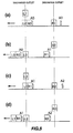
- Containers C are arranged in a row by the operation to be described below.
- a holder 24 is brought to a halt at the discharge station 5, whereupon the pusher pin 34 comes into contact with the bottom of the container C held by the holder 24, lifting the container C from the holder 24 for discharging.
- the container C discharged from the holder 24 is lifted along the guide plate 32, allowed to fall from the upper end thereof as turned upside down and received by the slide plate 13.
- FIG. 5(a) shows a container R1 discharged from the right discharge unit 31, as it is supported at a right receiving position on the slide plate 13.
- one pusher member A1 is positioned at the right of the container R1.
- two containers L0, R0 discharged by the preceding cycle and being pushed forward by another pusher member A0 are located in the vicinity of a left receiving position.
- the pusher member A1 positioned at the right of the container R1 is moved leftward, the pusher member A1 comes into contact with the container R1, pushing the container R1 leftward from the right receiving position.
- FIG. 5(c) shows the same state as FIG. 5(a).
- Another pusher member A2 is positioned at the right side of the container R2 supported at the right receiving position. The container R1 being pushed between the left receiving position and the right receiving position comes into contact with the container L1 at the left receiving position, and the latter container L1 is pushed by the former container R1 in contact therewith.
- containers are in the state shown in FIG. 5(d), i.e., the same state as shown in FIG. 5(b).
- a container L2 discharged from the left discharge unit 31 is supported at the left receiving position on the slide plate 13.
- the two containers L1, R1 discharged by the preceding cycle have moved past the left receiving position, and are pushed leftward in contact with each other.
- the two containers L1, R1 discharged by one cycle are pushed leftward on the slide plate 13 by one pusher member A1.
- the containers L1, R1 Upon the containers L1, R1 reaching the location of the guide rails 17, 18, the containers L1, R1 are guided forward by the guide rails 17, 18 while being moved leftward on the slide plate 13, then transferred from the slide plate 13 to the transport path of the third conveyor 16 and further transported on the path as arranged in a row.
- the second conveyor 12 and the third conveyor 16 are arranged in parallel in the foregoing embodiment, whereas the conveyors 12, 16 are arranged in series according to the modifications to be described next.
- the endless chains 14 of the second conveyor 12 have a lower path of movement extending along the rear edge of the slide plate 13.
- the third conveyor 16 is so disposed that the starting end of its transport path is connected to the left end of the slide plate 16. In this case, the containers C on the slide plate 13 are transferred to the third conveyor 16 by being pushed by pusher members 15.
- the second conveyor 12 has endless chains 14 arranged horizontally and having a rear path of movement which extends along the front edge of the slide plate 13.
Landscapes
- Engineering & Computer Science (AREA)
- Mechanical Engineering (AREA)
- Special Conveying (AREA)
- Attitude Control For Articles On Conveyors (AREA)
- Branching, Merging, And Special Transfer Between Conveyors (AREA)
- Relays Between Conveyors (AREA)
Claims (9)
- Dispositif de transport d'objets, comprenant un premier convoyeur (11) comportant au moins une trajectoire de transport (21) s'étendant vers l'avant, un dispositif de livraison (10) destiné à délivrer des objets (C) vers l'avant à partir d'une extrémité avant de chaque trajectoire de transport du premier convoyeur (11), un second convoyeur (12) comprenant une plaque de coulissement fixe (13) disposée pour recevoir les objets (C) délivrés par le dispositif de livraison (10) et formant une trajectoire de transport qui s'étend dans une direction orthogonale à chaque trajectoire de transport du premier convoyeur (11), caractérisé en ce qu'à proximité de chaque côté de la plaque de coulissement fixe (13), il est prévu des moyens de guidage (41-43) situés à un niveau plus élevé que ladite plaque de coulissement (13), tandis que le dispositif de livraison (10) est conçu pour guider les objets sur les moyens de guidage montés du côté de la plaque de coulissement qui est dirigé vers lui, et qu'un organe pousseur (15) est disposé de façon à pouvoir être déplacé au-dessus de la plaque de coulissement (13) à une vitesse constante.
- Dispositif selon la revendication 1, dans lequel le dispositif de livraison comprend une plaque de guidage (32) inclinée vers le haut dans la direction de la plaque de coulissement (13).
- Dispositif selon la revendication 1 ou 2, dans lequel du côté de la plaque de coulissement (13) opposé au dispositif de livraison (10), les moyens de guidage sont formés par une plaque de guidage (42) qui s'étend sensiblement verticalement.
- Dispositif selon l'une quelconque des revendications précédentes, dans lequel le premier convoyeur (11) apte à être entraíné de manière intermittente comporte deux trajectoires de transport s'étendant vers l'avant pour transporter des objets (C) avec un décalage de' phase de 1/2 cycle entre les deux trajectoires de transport, le dispositif de livraison (10) délivrant les objets (C) un par un vers l'avant à partir des extrémités avant des deux trajectoires de transport du premier convoyeur (11) de manière alternée.
- Dispositif selon l'une quelconque des revendications précédentes, dans lequel le dispositif comprend une chaíne sans fin (14) apte à être entraínée de manière continue et comportant une trajectoire de déplacement rectiligne qui s'étend le long de la plaque de coulissement (13), et plusieurs organes pousseurs (15) reliés à la chaíne (14) de manière à s'avancer au-dessus de la plaque de coulissement (13), et disposés à intervalles égaux.
- Dispositif selon l'une quelconque des revendications précédentes, dans lequel le dispositif comprend un troisième convoyeur (16) apte à être entraíné de manière continue dans le même sens de déplacement que l'organe pousseur (15) et comportant une trajectoire de transport reliée à la plaque de coulissement (13) parallèlement à celle-ci, et un rail de guidage (18) qui s'étend obliquement en travers de la plaque de coulissement (13) et au-dessus de celle-ci afin de guider des objets (C) en direction du troisième convoyeur (16).
- Dispositif selon l'une quelconque des revendications précédentes, dans lequel le dispositif comprend un troisième convoyeur (16) apte à être entraíné de manière continue dans le même sens de déplacement que l'organe pousseur (15) et comportant une trajectoire de transport disposée en alignement avec la trajectoire de transport définie par la plaque de coulissement (13).
- Dispositif selon la revendication 6 ou 7 précédente, dans lequel la vitesse de déplacement de l'organe pousseur (15) est la même que la vitesse à laquelle le troisième convoyeur (16) est entraíné.
- Dispositif selon l'une quelconque des revendications précédentes, dans lequel les deux trajectoires de transport du premier convoyeur (11) ont été conçues pour délivrer respectivement des objets (c) à une position de réception amont et à une position de réception aval sur la plaque de coulissement (13), tandis que les moyens destinés à entraíner le premier convoyeur et les organes pousseurs (15) ont été conçus pour que, lorsqu'un objet (C) est délivré à la position de réception aval, un autre objet (C) délivré à la position de réception amont en étant poussé par l'un des organes pousseurs (15) soit positionné entre les deux positions de réception.
Applications Claiming Priority (3)
| Application Number | Priority Date | Filing Date | Title |
|---|---|---|---|
| JP333290/95 | 1995-12-21 | ||
| JP33329095 | 1995-12-21 | ||
| JP7333290A JPH09169430A (ja) | 1995-12-21 | 1995-12-21 | 物品搬送装置 |
Publications (2)
| Publication Number | Publication Date |
|---|---|
| EP0780329A1 EP0780329A1 (fr) | 1997-06-25 |
| EP0780329B1 true EP0780329B1 (fr) | 1999-12-01 |
Family
ID=18264449
Family Applications (1)
| Application Number | Title | Priority Date | Filing Date |
|---|---|---|---|
| EP19960203623 Expired - Lifetime EP0780329B1 (fr) | 1995-12-21 | 1996-12-19 | Dispositif de transport d'articles |
Country Status (4)
| Country | Link |
|---|---|
| EP (1) | EP0780329B1 (fr) |
| JP (1) | JPH09169430A (fr) |
| DE (1) | DE69605391T2 (fr) |
| DK (1) | DK0780329T3 (fr) |
Families Citing this family (2)
| Publication number | Priority date | Publication date | Assignee | Title |
|---|---|---|---|---|
| JP3816160B2 (ja) * | 1996-09-17 | 2006-08-30 | 四国化工機株式会社 | 容器搬出装置 |
| DE19802062C1 (de) * | 1998-01-21 | 1999-09-16 | Meurer Franz Josef | Verfahren und Vorrichtung zum Fördern von Produkten |
Family Cites Families (2)
| Publication number | Priority date | Publication date | Assignee | Title |
|---|---|---|---|---|
| GB356648A (en) * | 1931-02-17 | 1931-09-10 | Morgan Construction Co | Improvements in or relating to conveyor mechanism |
| IT1090264B (it) * | 1977-09-21 | 1985-06-26 | Amf Sasib | Dispositivo trasferitore combinatore ad intercalamento per comporre piu linee di alimentazione di oggetti regolari in una singola linea |
-
1995
- 1995-12-21 JP JP7333290A patent/JPH09169430A/ja not_active Withdrawn
-
1996
- 1996-12-19 DE DE1996605391 patent/DE69605391T2/de not_active Expired - Fee Related
- 1996-12-19 EP EP19960203623 patent/EP0780329B1/fr not_active Expired - Lifetime
- 1996-12-19 DK DK96203623T patent/DK0780329T3/da active
Also Published As
| Publication number | Publication date |
|---|---|
| DE69605391T2 (de) | 2000-05-11 |
| EP0780329A1 (fr) | 1997-06-25 |
| JPH09169430A (ja) | 1997-06-30 |
| DK0780329T3 (da) | 2000-05-01 |
| DE69605391D1 (de) | 2000-01-05 |
Similar Documents
| Publication | Publication Date | Title |
|---|---|---|
| US6993889B2 (en) | Product packaging system | |
| US8011492B2 (en) | Device for the accumulation and release of products, especially products arranged in ranks feeding packaging lines for such products | |
| US4443995A (en) | Metering device and method | |
| GB2061893A (en) | Pipe feeding apparatus | |
| US5450941A (en) | Apparatus for separating, conveying and grouping flat items | |
| CZ298707B6 (cs) | Zpusob a zarízení k preprave foliových sácku | |
| JPH06316329A (ja) | 固形物の搬送装置 | |
| US20030159903A1 (en) | Method and device for transferring a product in a packaging machine | |
| EP0673342A1 (fr) | Procede et appareil d'empilage reorientant des articles le long d'une ligne generalement helicoidale tout en les transportant d'une station de chargement a une station de dechargement. | |
| US3366220A (en) | Method and apparatus for single filing | |
| JP3585945B2 (ja) | 自動集積供給装置 | |
| EP0707551A1 (fr) | Procede et appareil d'insertion d'elements entre des articles | |
| US3297129A (en) | Apparatus for conveying chocolate bars or slabs | |
| EP1533257B1 (fr) | Station pour raccorder une machine d'emballage, en particulier une machine de fabrication de blisters, à une ligne d'alimentation d'une machine d'encaissage | |
| EP0780329B1 (fr) | Dispositif de transport d'articles | |
| US6397563B1 (en) | Method and device for packaging flat products | |
| GB2097744A (en) | Packet handling apparatus | |
| JP3795674B2 (ja) | 長物農産物の供給装置 | |
| JP3585946B2 (ja) | 自動集積供給装置 | |
| EP1433727B1 (fr) | Dispositif pour vider des récipients de fruits et légumes | |
| JPH11123367A (ja) | 欠陥のある平らな物品を排除し、欠陥のない平らな物品のスタックを形成するための装置 | |
| JP2515116Y2 (ja) | 作物の選別用搬送装置 | |
| JPH0977241A (ja) | 物品分配装置 | |
| GB2116508A (en) | A method and an apparatus for forming several stacks which lie side by side | |
| JPH0656108A (ja) | 袋状物品の駒立て搬送装置及びその袋状物品のロジ詰め装置 |
Legal Events
| Date | Code | Title | Description |
|---|---|---|---|
| PUAI | Public reference made under article 153(3) epc to a published international application that has entered the european phase |
Free format text: ORIGINAL CODE: 0009012 |
|
| AK | Designated contracting states |
Kind code of ref document: A1 Designated state(s): CH DE DK FR GB LI NL SE |
|
| 17P | Request for examination filed |
Effective date: 19971009 |
|
| 17Q | First examination report despatched |
Effective date: 19980911 |
|
| GRAG | Despatch of communication of intention to grant |
Free format text: ORIGINAL CODE: EPIDOS AGRA |
|
| GRAG | Despatch of communication of intention to grant |
Free format text: ORIGINAL CODE: EPIDOS AGRA |
|
| GRAH | Despatch of communication of intention to grant a patent |
Free format text: ORIGINAL CODE: EPIDOS IGRA |
|
| GRAH | Despatch of communication of intention to grant a patent |
Free format text: ORIGINAL CODE: EPIDOS IGRA |
|
| GRAA | (expected) grant |
Free format text: ORIGINAL CODE: 0009210 |
|
| AK | Designated contracting states |
Kind code of ref document: B1 Designated state(s): CH DE DK FR GB LI NL SE |
|
| REG | Reference to a national code |
Ref country code: CH Ref legal event code: NV Representative=s name: PATENTANWALTSBUERO JEAN HUNZIKER Ref country code: CH Ref legal event code: EP |
|
| REF | Corresponds to: |
Ref document number: 69605391 Country of ref document: DE Date of ref document: 20000105 |
|
| ET | Fr: translation filed | ||
| REG | Reference to a national code |
Ref country code: DK Ref legal event code: T3 |
|
| PLBE | No opposition filed within time limit |
Free format text: ORIGINAL CODE: 0009261 |
|
| STAA | Information on the status of an ep patent application or granted ep patent |
Free format text: STATUS: NO OPPOSITION FILED WITHIN TIME LIMIT |
|
| 26N | No opposition filed | ||
| PGFP | Annual fee paid to national office [announced via postgrant information from national office to epo] |
Ref country code: GB Payment date: 20011204 Year of fee payment: 6 |
|
| REG | Reference to a national code |
Ref country code: GB Ref legal event code: IF02 |
|
| PGFP | Annual fee paid to national office [announced via postgrant information from national office to epo] |
Ref country code: CH Payment date: 20020103 Year of fee payment: 6 |
|
| PGFP | Annual fee paid to national office [announced via postgrant information from national office to epo] |
Ref country code: DE Payment date: 20021114 Year of fee payment: 7 |
|
| PGFP | Annual fee paid to national office [announced via postgrant information from national office to epo] |
Ref country code: SE Payment date: 20021216 Year of fee payment: 7 |
|
| PGFP | Annual fee paid to national office [announced via postgrant information from national office to epo] |
Ref country code: DK Payment date: 20021218 Year of fee payment: 7 |
|
| PG25 | Lapsed in a contracting state [announced via postgrant information from national office to epo] |
Ref country code: GB Free format text: LAPSE BECAUSE OF NON-PAYMENT OF DUE FEES Effective date: 20021219 |
|
| PGFP | Annual fee paid to national office [announced via postgrant information from national office to epo] |
Ref country code: FR Payment date: 20021223 Year of fee payment: 7 |
|
| PGFP | Annual fee paid to national office [announced via postgrant information from national office to epo] |
Ref country code: NL Payment date: 20021230 Year of fee payment: 7 |
|
| PG25 | Lapsed in a contracting state [announced via postgrant information from national office to epo] |
Ref country code: LI Free format text: LAPSE BECAUSE OF NON-PAYMENT OF DUE FEES Effective date: 20021231 Ref country code: CH Free format text: LAPSE BECAUSE OF NON-PAYMENT OF DUE FEES Effective date: 20021231 |
|
| GBPC | Gb: european patent ceased through non-payment of renewal fee |
Effective date: 20021219 |
|
| REG | Reference to a national code |
Ref country code: CH Ref legal event code: PL |
|
| PG25 | Lapsed in a contracting state [announced via postgrant information from national office to epo] |
Ref country code: SE Free format text: LAPSE BECAUSE OF NON-PAYMENT OF DUE FEES Effective date: 20031220 |
|
| PG25 | Lapsed in a contracting state [announced via postgrant information from national office to epo] |
Ref country code: DK Free format text: LAPSE BECAUSE OF NON-PAYMENT OF DUE FEES Effective date: 20040102 |
|
| PG25 | Lapsed in a contracting state [announced via postgrant information from national office to epo] |
Ref country code: NL Free format text: LAPSE BECAUSE OF NON-PAYMENT OF DUE FEES Effective date: 20040701 Ref country code: DE Free format text: LAPSE BECAUSE OF NON-PAYMENT OF DUE FEES Effective date: 20040701 |
|
| EUG | Se: european patent has lapsed | ||
| REG | Reference to a national code |
Ref country code: DK Ref legal event code: EBP |
|
| PG25 | Lapsed in a contracting state [announced via postgrant information from national office to epo] |
Ref country code: FR Free format text: LAPSE BECAUSE OF NON-PAYMENT OF DUE FEES Effective date: 20040831 |
|
| NLV4 | Nl: lapsed or anulled due to non-payment of the annual fee |
Effective date: 20040701 |
|
| REG | Reference to a national code |
Ref country code: FR Ref legal event code: ST |