EP0659675A1 - Dispositif de chargement et de déchargement de bobines dans un bobinoir textile - Google Patents
Dispositif de chargement et de déchargement de bobines dans un bobinoir textile Download PDFInfo
- Publication number
- EP0659675A1 EP0659675A1 EP94120180A EP94120180A EP0659675A1 EP 0659675 A1 EP0659675 A1 EP 0659675A1 EP 94120180 A EP94120180 A EP 94120180A EP 94120180 A EP94120180 A EP 94120180A EP 0659675 A1 EP0659675 A1 EP 0659675A1
- Authority
- EP
- European Patent Office
- Prior art keywords
- cops
- guide
- cop
- loading
- unloading
- Prior art date
- Legal status (The legal status is an assumption and is not a legal conclusion. Google has not performed a legal analysis and makes no representation as to the accuracy of the status listed.)
- Granted
Links
- 239000004753 textile Substances 0.000 title claims abstract description 36
- 238000004804 winding Methods 0.000 title claims abstract description 32
- 230000000903 blocking effect Effects 0.000 claims 1
- 239000012530 fluid Substances 0.000 description 1
- 230000005484 gravity Effects 0.000 description 1
- 230000001050 lubricating effect Effects 0.000 description 1
- 238000012423 maintenance Methods 0.000 description 1
Images
Classifications
-
- B—PERFORMING OPERATIONS; TRANSPORTING
- B65—CONVEYING; PACKING; STORING; HANDLING THIN OR FILAMENTARY MATERIAL
- B65H—HANDLING THIN OR FILAMENTARY MATERIAL, e.g. SHEETS, WEBS, CABLES
- B65H67/00—Replacing or removing cores, receptacles, or completed packages at paying-out, winding, or depositing stations
- B65H67/04—Arrangements for removing completed take-up packages and or replacing by cores, formers, or empty receptacles at winding or depositing stations; Transferring material between adjacent full and empty take-up elements
- B65H67/0405—Arrangements for removing completed take-up packages or for loading an empty core
-
- B—PERFORMING OPERATIONS; TRANSPORTING
- B65—CONVEYING; PACKING; STORING; HANDLING THIN OR FILAMENTARY MATERIAL
- B65H—HANDLING THIN OR FILAMENTARY MATERIAL, e.g. SHEETS, WEBS, CABLES
- B65H2701/00—Handled material; Storage means
- B65H2701/30—Handled filamentary material
- B65H2701/31—Textiles threads or artificial strands of filaments
-
- Y—GENERAL TAGGING OF NEW TECHNOLOGICAL DEVELOPMENTS; GENERAL TAGGING OF CROSS-SECTIONAL TECHNOLOGIES SPANNING OVER SEVERAL SECTIONS OF THE IPC; TECHNICAL SUBJECTS COVERED BY FORMER USPC CROSS-REFERENCE ART COLLECTIONS [XRACs] AND DIGESTS
- Y10—TECHNICAL SUBJECTS COVERED BY FORMER USPC
- Y10S—TECHNICAL SUBJECTS COVERED BY FORMER USPC CROSS-REFERENCE ART COLLECTIONS [XRACs] AND DIGESTS
- Y10S414/00—Material or article handling
- Y10S414/124—Roll handlers
Definitions
- the present invention relates to a device for the loading and unloading of cops in textile apparatus for winding yarn.
- the known devices for loading and feeding cops to textile winding apparatus comprise, essentially, a support structure, a first fixed guide for loading cops towards a respective area for pick-up of the cops by suitable arms of the winding machine, and a second fixed guide for unloading the cops which extends from a second area for transfer of the cops loaded with yarn by the arms of the winding machine.
- a feed and guide chute provided in front of the winding machine also interferes with the manoeuvres of the operators in charge of the machine who must deal with the initial operations of inserting the yarn and maintenance of the other devices of the winding machine.
- said front chutes must necessarily be of limited length since otherwise they would impede the operators' work excessively and could interfere with other functions of the winding machine, for example the function of guiding the yarn towards the winding sections.
- the object of the present invention is that of providing a device for loading and unloading cops, in textile apparatus for winding yarn, which has small overall dimensions, smaller than those of similar devices already known.
- Another object of the present invention is that of providing a device for loading and unloading cops in textile apparatus, more particularly in yarn winding apparatus, which does not interfere with the movements or at any rate facilitates the functions performed by additional devices of the textile machine, as well as allowing improved accessibility for the staff in charge to the various components of the winding machine.
- Another object of the present invention is that of providing a device for loading and unloading cops which does not require the constant presence of the staff in charge.
- a further object of the present invention is that of providing a device for loading and unloading cops which suitably feeds one cop at a time for each winding cycle of a textile machine and accurately positions the same in the pick-up area for an easy grip by the arms of the textile machine.
- a cop guide element which moves to define in a first position said cop loading guide and in a second position said cop unloading guide, allows the cop loading and unloading device to occupy a small volume. In fact it allows empty cops and full cops, at different times, to pass by the same points of the device, enabling a cop loading-unloading device to be obtained with small dimensions and such that it does not impede the other devices of the textile machine.
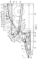
- Fig. 1 shows a device 10 for loading empty cops 12 and unloading cops full of yarn 14 to and from the textile yarn winding machine 16 respectively.
- the textile winding apparatus 16 comprises a cop-holder arm 18 designed to pick up, in the position shown by a dotted line in Fig. 1, an empty cop 12, and support it during the phase of winding the yarn F, which according to this embodiment is performed in the lowered position of said arm 18, and to return it to said device 10, at the end of the yarn winding operation, in the abovementioned raised position shown by the dotted line.
- the cop-holder arm 18 in the two abovementioned working positions, the support structure 20, yarn drive parts 22 which guide the yarn towards the collection cop passing through suitable parts for guiding the yarn being wound on the cop (not shown), as well as suitable parts for the movement of the various elements of the winding machine, namely a cop drive roller 24, a cylinder 26 for the movement of the cop-holder arm 18 and an arched guide 28 for said arm 18.
- Figure 1 also shows a device 27 for trapping and inserting yarn on the reel and an oiling device 29 for lubricating the yarn.
- the device 10 of the present invention comprises a first guide 30, whereon the empty cops 12 slide for loading of the winding apparatus 16, and a second guide 32 for the sliding of the cops loaded with yarn 14 to be unloaded by the same winding apparatus.
- fixed guide portions 36, 38 have been provided to form a guide element for the empty cops 12 and for the full cops 14 respectively.
- Said fixed guide portions 36, 38 for loading and unloading cops develop on the extension of said mobile guide element 34 and are arranged in the raised position, shown by a dotted line, and in the lower position, shown by an unbroken line, respectively.
- the guides for loading and unloading of the cops may be provided on the same side of the textile machine with the guide for loading empty cops which is arranged above the guide for unloading full cops.
- the fixed portion 36 of the upper unloading guide 30 is provided distanced from the underlying lower loading guide 32 so as to allow the passage of the full cops 14 for unloading.
- said slide guides of the cops 30, 32 comprise a first and a second lateral track suitable for supporting said cops at the end edges of the latter.
- the mobile guide element 34 is hinged at one of its ends in 40, at the cop pick-up and transfer zone, and is driven rotatably to position in the two aforementioned lower and upper positions by drive means formed by a piston contained in a pneumatic cylinder 42.
- the mobile element 34 may be attached rotatably to the support structure 20 or advantageously attached to a front extension 44 of said fixed portion 38 of the unloading guide 32.
- said mobile guide element 34 in its lower position, to arrange its upper surface 35 for the sliding of the cops below an upper surface 39 of said front extension 44 of the fixed portion of the cop unloading guide 32, so as to discharge said means for driving the movement of the element 34 of the task of positioning precisely said mobile element 34 also in the lower position.
- means 45 are provided for positioning and stopping the empty cops 12 sliding on the cop loading guide 30. They comprise a mobile part 46 arranged in a position above said cop loading guide 30, at the pick-up and transfer zone. It is attached rotatably in 48, by one of its ends, to said support structure 20.
- the mobile part 46 is driven by suitable drive parts, consisting of a piston housed in a pneumatic cylinder 50, to occupy a lowered position (shown by the dotted line) in order to stop and position the cops sliding on said loading guide 32 and in a second raised position (shown by the unbroken line) wherein it allows the free movement of the cop by the cop-holder arm 18 both to take it into the front yarn winding zone and to pass it to the rear of the full cop unloading guide 32.
- suitable drive parts consisting of a piston housed in a pneumatic cylinder 50, to occupy a lowered position (shown by the dotted line) in order to stop and position the cops sliding on said loading guide 32 and in a second raised position (shown by the unbroken line) wherein it allows the free movement of the cop by the cop-holder arm 18 both to take it into the front yarn winding zone and to pass it to the rear of the full cop unloading guide 32.
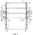
- said mobile part for stopping the cops 46 comprises a first and a second lateral arm, suitable for engaging said empty cop 12 at the longitudinal ends of the latter, so as to provide a stop for the cops without the risk of turning them over.
- said stopping arms 46 In order to adapt better to the circular shape of said cops 12 so as to provide a better stop for the cops which slide on the loading guide 30, said stopping arms 46 have a cop stop face 47 which is bent with a curve which matches the curve of the cops themselves.
- suitable means are provided for feeding empty cops to said cop loading guide, capable of placing, in a cadenced manner, on said guide 30 for loading empty cops, only one cop at a time for each working cycle of yarn winding.
- said means for feeding in a cadenced manner the cops to said loading guide comprise a guide 56 for feeding on the extension of said loading guide 30 and arranged tilting downwards, towards the pick-up and transfer zone, with a smaller slant than that of said loading guide 30 and a first and a second stopping device for a line of empty cops 12 located on said feed guide 56, denoted by 58 and 60 respectively in the figures.
- the first stopping element 58 is positioned at the first cop 12a of the line and defines the point of release of the cops by said cadenced feed means. It is normally actuated to close for the stop of all the cops present on the feed guide 56, while said second stopping element 60 is provided at a certain distance from said first stopping element 58, in a position such that it blocks the second cop 12b of the line of empty cops 12. It is normally actuated in an open condition to allow cops to slide freely on the guide 56.
- Suitable means are provided for actuating the opening and closure of said stopping elements and are suitable for actuating, following a cop request signal, the simultaneous opening of the first stopping element 58 and closure of the second stopping element 60, so as to allow the forward movement of the first cop 12a of the line of cops towards and onto the loading guide 32 and to block all the remaining cops of the line. Having ended this release operation, said stopping elements return to their normal conditions, the open one for the second stopping element 60, to allow forward sliding of the line of cops, and the closed one respectively for the first stopping element 58, to block the forward sliding of the line of cops.
- each of said first and second stopping elements comprise respectively a first and a second mobile pin 62a,b and 64a,b each provided at a respective side of said cops.
- the pins 62a,b and 64a,b are driven by said drive means into a forward closure position by means of respective drive pistons provided inside respective cylinders 66a,b and 68a,b which are attached by means of respective screws 70 and brackets 72 to the support structure 20.
- Said pistons for driving the stopping pins are actuated by a pressurised fluid under the control of a microprocessor (not shown in the drawings).
Landscapes
- Replacing, Conveying, And Pick-Finding For Filamentary Materials (AREA)
- Spinning Or Twisting Of Yarns (AREA)
Applications Claiming Priority (2)
| Application Number | Priority Date | Filing Date | Title |
|---|---|---|---|
| IT93MI002735A IT1265447B1 (it) | 1993-12-24 | 1993-12-24 | Dispositivo per il carico e lo scarico di tubetti in un'apparecchiatura tessile di bobinatura |
| ITMI932735 | 1993-12-24 |
Publications (2)
| Publication Number | Publication Date |
|---|---|
| EP0659675A1 true EP0659675A1 (fr) | 1995-06-28 |
| EP0659675B1 EP0659675B1 (fr) | 1999-03-17 |
Family
ID=11367411
Family Applications (1)
| Application Number | Title | Priority Date | Filing Date |
|---|---|---|---|
| EP94120180A Expired - Lifetime EP0659675B1 (fr) | 1993-12-24 | 1994-12-20 | Dispositif de chargement et de déchargement de bobines dans un bobinoir textile |
Country Status (4)
| Country | Link |
|---|---|
| US (1) | US5551827A (fr) |
| EP (1) | EP0659675B1 (fr) |
| DE (1) | DE69417181T2 (fr) |
| IT (1) | IT1265447B1 (fr) |
Families Citing this family (4)
| Publication number | Priority date | Publication date | Assignee | Title |
|---|---|---|---|---|
| DE19727325C2 (de) * | 1997-06-27 | 2003-08-28 | Voith Paper Patent Gmbh | Wickeleinrichtung für eine Materialbahn, insbesondere für eine Rollenschneidvorrichtung |
| US6092977A (en) * | 1998-07-22 | 2000-07-25 | Japan Tobacco Inc. | Rod-shaped article supplying apparatus |
| US6260788B1 (en) * | 1998-10-05 | 2001-07-17 | Valmet-Karlstad Ab | Reel-up and associated method |
| CN112722938A (zh) * | 2020-12-31 | 2021-04-30 | 成都智汶汇物商贸有限公司 | 一种智能制造薄膜绕卷打包自动定量切割封合的装置 |
Citations (5)
| Publication number | Priority date | Publication date | Assignee | Title |
|---|---|---|---|---|
| FR886319A (fr) * | 1941-10-18 | 1943-10-12 | Sachsische Textilmaschinenfabr | Dispositif de changement automatique des bobines des étireuses et autres machines de filature |
| CH432311A (de) * | 1963-09-26 | 1967-03-15 | Reiter Michael | Aufwinde-Einrichtung an einer Vorgarnstrecke zum Herstellen von Vorgarnspulen |
| CH556784A (de) * | 1973-04-12 | 1974-12-13 | Heberlein & Co Ag | Automatische spulenwechsel- und -transportvorrichtung. |
| US4451007A (en) * | 1981-01-16 | 1984-05-29 | Toray Industries, Inc. | Yarn winding apparatus |
| FR2663916A1 (fr) * | 1990-06-27 | 1992-01-03 | Riva Srl Off Mec | Dispositif de dechargement automatique de bobines textiles. |
Family Cites Families (10)
| Publication number | Priority date | Publication date | Assignee | Title |
|---|---|---|---|---|
| DE351076C (de) * | 1922-03-31 | Elga Elek Sche Gasreinigungs G | Verfahren und Einrichtung zum Schutze der Isolation bei der elektrischen Gasreinigung | |
| US3610545A (en) * | 1969-01-17 | 1971-10-05 | Reifenhauser Kg Maschinenfabri | Apparatus for winding continuously produced layer material on elongated core |
| US4196865A (en) * | 1978-10-19 | 1980-04-08 | Patriksson Stig S | Method for the transfer of a forwards-travelling material web from a first take-up roller to a second take-up roller and means for carrying out the method |
| EP0113589B1 (fr) * | 1982-11-09 | 1986-10-29 | Keiko Tagawa | Dispositif pour convoyer des rouleaux de tissus sur une machine à enrouler du tissu et pour enlever les tores vides de ces rouleaux |
| JPS59128128A (ja) * | 1983-01-13 | 1984-07-24 | Matsushita Electric Works Ltd | 積載方法 |
| DE3528743A1 (de) * | 1985-08-10 | 1987-02-12 | Kurt Breuning | Materialstangenzufuehrvorrichtung |
| US4744720A (en) * | 1986-06-13 | 1988-05-17 | Valmet-Dominion Inc. | Reel bar loading device |
| US5022439A (en) * | 1988-07-20 | 1991-06-11 | Nissan Motor Co., Ltd. | Cloth roller replacing system for loom |
| EP0410019A1 (fr) * | 1989-07-24 | 1991-01-30 | Palitex Project-Company GmbH | Procédé et dispositif pour remplacer automatiquement les bobines, en particulier les bobines croisées, avec les bobines vides |
| EP0473134B1 (fr) * | 1990-08-31 | 1996-06-26 | TEIJIN SEIKI CO. Ltd. | Dispositif automatique pour échanger des bobines sur une machine de bobinage |
-
1993
- 1993-12-24 IT IT93MI002735A patent/IT1265447B1/it active IP Right Grant
-
1994
- 1994-12-20 DE DE69417181T patent/DE69417181T2/de not_active Expired - Fee Related
- 1994-12-20 EP EP94120180A patent/EP0659675B1/fr not_active Expired - Lifetime
- 1994-12-23 US US08/363,521 patent/US5551827A/en not_active Expired - Fee Related
Patent Citations (5)
| Publication number | Priority date | Publication date | Assignee | Title |
|---|---|---|---|---|
| FR886319A (fr) * | 1941-10-18 | 1943-10-12 | Sachsische Textilmaschinenfabr | Dispositif de changement automatique des bobines des étireuses et autres machines de filature |
| CH432311A (de) * | 1963-09-26 | 1967-03-15 | Reiter Michael | Aufwinde-Einrichtung an einer Vorgarnstrecke zum Herstellen von Vorgarnspulen |
| CH556784A (de) * | 1973-04-12 | 1974-12-13 | Heberlein & Co Ag | Automatische spulenwechsel- und -transportvorrichtung. |
| US4451007A (en) * | 1981-01-16 | 1984-05-29 | Toray Industries, Inc. | Yarn winding apparatus |
| FR2663916A1 (fr) * | 1990-06-27 | 1992-01-03 | Riva Srl Off Mec | Dispositif de dechargement automatique de bobines textiles. |
Also Published As
| Publication number | Publication date |
|---|---|
| ITMI932735A0 (it) | 1993-12-24 |
| US5551827A (en) | 1996-09-03 |
| DE69417181T2 (de) | 1999-11-18 |
| DE69417181D1 (de) | 1999-04-22 |
| EP0659675B1 (fr) | 1999-03-17 |
| ITMI932735A1 (it) | 1995-06-24 |
| IT1265447B1 (it) | 1996-11-22 |
Similar Documents
| Publication | Publication Date | Title |
|---|---|---|
| US5033623A (en) | Method and apparatus for associating information with a textile package | |
| US3674159A (en) | Load handling mechanism and automatic storage system | |
| US4548537A (en) | Apparatus for taking up rod type materials | |
| US11866254B2 (en) | Overhead conveying system and method for determining the thickness of a hanging bag | |
| US4697310A (en) | Device for exchanging empty cans with cans filled with sliver | |
| EP2187723A1 (fr) | Changeur automatique de bobine | |
| RU2759553C2 (ru) | Устройство и способ для манипулирования прутками | |
| GB2066761A (en) | Handling rod-like articles | |
| US4022338A (en) | Conveyor loader device | |
| EP0659675B1 (fr) | Dispositif de chargement et de déchargement de bobines dans un bobinoir textile | |
| CN216806781U (zh) | 挂入机构、进仓装置、入库设备以及带式仓储系统 | |
| CN216806783U (zh) | 阻挡缓冲组件、进仓装置、入库设备以及带式仓储系统 | |
| CN108502637B (zh) | 一种插纱装置 | |
| US4925000A (en) | Device for positioning bobbins with yarn packages | |
| JP2001072340A (ja) | あや巻きボビンを製作する紡織機械のための糸結装置 | |
| US4396335A (en) | Arrangement for orderly placing of cross wound spools | |
| US3876064A (en) | Bobbin conveying and alignment mechanism | |
| US5168695A (en) | Tube transport apparatus with intermediate stationary magazines dispensable to service carriage | |
| JPH06316324A (ja) | 円錐形のチューブを整向するための装置 | |
| CZ307292A3 (en) | Device for breakage of a fiber sliver in a filling station of a textile machine | |
| US5772000A (en) | Hop vine transfer system | |
| JP3506750B2 (ja) | 巻管装填装置 | |
| CN216970808U (zh) | 一种悬挂载具的打包线路架构及打包作业线 | |
| CZ176793A3 (en) | Process and apparatus for positioning conical or cylindrical cross wound bobbins | |
| US6012671A (en) | Tube feeding device for cheese-producing textile machines |
Legal Events
| Date | Code | Title | Description |
|---|---|---|---|
| PUAI | Public reference made under article 153(3) epc to a published international application that has entered the european phase |
Free format text: ORIGINAL CODE: 0009012 |
|
| AK | Designated contracting states |
Kind code of ref document: A1 Designated state(s): DE FR GB |
|
| 17P | Request for examination filed |
Effective date: 19951218 |
|
| 17Q | First examination report despatched |
Effective date: 19970404 |
|
| GRAG | Despatch of communication of intention to grant |
Free format text: ORIGINAL CODE: EPIDOS AGRA |
|
| GRAG | Despatch of communication of intention to grant |
Free format text: ORIGINAL CODE: EPIDOS AGRA |
|
| GRAH | Despatch of communication of intention to grant a patent |
Free format text: ORIGINAL CODE: EPIDOS IGRA |
|
| GRAH | Despatch of communication of intention to grant a patent |
Free format text: ORIGINAL CODE: EPIDOS IGRA |
|
| GRAA | (expected) grant |
Free format text: ORIGINAL CODE: 0009210 |
|
| AK | Designated contracting states |
Kind code of ref document: B1 Designated state(s): DE FR GB |
|
| REF | Corresponds to: |
Ref document number: 69417181 Country of ref document: DE Date of ref document: 19990422 |
|
| ET | Fr: translation filed | ||
| PLBE | No opposition filed within time limit |
Free format text: ORIGINAL CODE: 0009261 |
|
| STAA | Information on the status of an ep patent application or granted ep patent |
Free format text: STATUS: NO OPPOSITION FILED WITHIN TIME LIMIT |
|
| 26N | No opposition filed | ||
| PGFP | Annual fee paid to national office [announced via postgrant information from national office to epo] |
Ref country code: FR Payment date: 20001222 Year of fee payment: 7 |
|
| PGFP | Annual fee paid to national office [announced via postgrant information from national office to epo] |
Ref country code: GB Payment date: 20001228 Year of fee payment: 7 |
|
| PGFP | Annual fee paid to national office [announced via postgrant information from national office to epo] |
Ref country code: DE Payment date: 20001229 Year of fee payment: 7 |
|
| PG25 | Lapsed in a contracting state [announced via postgrant information from national office to epo] |
Ref country code: GB Free format text: LAPSE BECAUSE OF NON-PAYMENT OF DUE FEES Effective date: 20011220 |
|
| REG | Reference to a national code |
Ref country code: GB Ref legal event code: IF02 |
|
| PG25 | Lapsed in a contracting state [announced via postgrant information from national office to epo] |
Ref country code: DE Free format text: LAPSE BECAUSE OF NON-PAYMENT OF DUE FEES Effective date: 20020702 |
|
| GBPC | Gb: european patent ceased through non-payment of renewal fee |
Effective date: 20011220 |
|
| PG25 | Lapsed in a contracting state [announced via postgrant information from national office to epo] |
Ref country code: FR Free format text: LAPSE BECAUSE OF NON-PAYMENT OF DUE FEES Effective date: 20020830 |
|
| REG | Reference to a national code |
Ref country code: FR Ref legal event code: ST |