EP0659961A1 - Serrure cylindrique - Google Patents
Serrure cylindrique Download PDFInfo
- Publication number
- EP0659961A1 EP0659961A1 EP19940118897 EP94118897A EP0659961A1 EP 0659961 A1 EP0659961 A1 EP 0659961A1 EP 19940118897 EP19940118897 EP 19940118897 EP 94118897 A EP94118897 A EP 94118897A EP 0659961 A1 EP0659961 A1 EP 0659961A1
- Authority
- EP
- European Patent Office
- Prior art keywords
- rotor
- key
- sleeve
- lock lever
- key rotor
- Prior art date
- Legal status (The legal status is an assumption and is not a legal conclusion. Google has not performed a legal analysis and makes no representation as to the accuracy of the status listed.)
- Granted
Links
- 230000008878 coupling Effects 0.000 claims abstract description 140
- 238000010168 coupling process Methods 0.000 claims abstract description 140
- 238000005859 coupling reaction Methods 0.000 claims abstract description 140
- 238000003780 insertion Methods 0.000 claims description 27
- 230000037431 insertion Effects 0.000 claims description 26
- 230000001105 regulatory effect Effects 0.000 claims description 7
- 238000010276 construction Methods 0.000 description 6
- 230000000717 retained effect Effects 0.000 description 2
Images









Classifications
-
- E—FIXED CONSTRUCTIONS
- E05—LOCKS; KEYS; WINDOW OR DOOR FITTINGS; SAFES
- E05B—LOCKS; ACCESSORIES THEREFOR; HANDCUFFS
- E05B17/00—Accessories in connection with locks
- E05B17/0054—Fraction or shear lines; Slip-clutches, resilient parts or the like for preventing damage when forced or slammed
- E05B17/0058—Fraction or shear lines; Slip-clutches, resilient parts or the like for preventing damage when forced or slammed with non-destructive disengagement
-
- E—FIXED CONSTRUCTIONS
- E05—LOCKS; KEYS; WINDOW OR DOOR FITTINGS; SAFES
- E05B—LOCKS; ACCESSORIES THEREFOR; HANDCUFFS
- E05B17/00—Accessories in connection with locks
- E05B17/04—Devices for coupling the turning cylinder of a single or a double cylinder lock with the bolt operating member
-
- Y—GENERAL TAGGING OF NEW TECHNOLOGICAL DEVELOPMENTS; GENERAL TAGGING OF CROSS-SECTIONAL TECHNOLOGIES SPANNING OVER SEVERAL SECTIONS OF THE IPC; TECHNICAL SUBJECTS COVERED BY FORMER USPC CROSS-REFERENCE ART COLLECTIONS [XRACs] AND DIGESTS
- Y10—TECHNICAL SUBJECTS COVERED BY FORMER USPC
- Y10T—TECHNICAL SUBJECTS COVERED BY FORMER US CLASSIFICATION
- Y10T70/00—Locks
- Y10T70/70—Operating mechanism
- Y10T70/7441—Key
- Y10T70/7486—Single key
- Y10T70/7508—Tumbler type
- Y10T70/7559—Cylinder type
- Y10T70/7667—Operating elements, parts and adjuncts
- Y10T70/7706—Operating connections
-
- Y—GENERAL TAGGING OF NEW TECHNOLOGICAL DEVELOPMENTS; GENERAL TAGGING OF CROSS-SECTIONAL TECHNOLOGIES SPANNING OVER SEVERAL SECTIONS OF THE IPC; TECHNICAL SUBJECTS COVERED BY FORMER USPC CROSS-REFERENCE ART COLLECTIONS [XRACs] AND DIGESTS
- Y10—TECHNICAL SUBJECTS COVERED BY FORMER USPC
- Y10T—TECHNICAL SUBJECTS COVERED BY FORMER US CLASSIFICATION
- Y10T70/00—Locks
- Y10T70/70—Operating mechanism
- Y10T70/7441—Key
- Y10T70/7915—Tampering prevention or attack defeating
- Y10T70/7949—Yielding or frangible connections
Definitions
- the invention relates to cylinder locks designed to prohibit wrongful unlocking.
- a cylinder lock arranged on a door of an automobile is designed as follows.
- a plurality of tumblers are arranged so as to be movable in radial directions in a key rotor that is rotatably arranged in a rotor case, and such plurality of tumblers are urged by springs in a single direction.
- the cylinder lock can be locked.
- the invention has been made in consideration of the aforementioned circumstances, and an object of the invention is therefore to provide a cylinder lock which not only is not unlocked, but also is used again by allowing no damaging force to be applied to components thereof such as tumblers so that the components will never be broken even if a key other than the regular key, a screwdriver, or the like is inserted into the keyhole of the key rotor to rotate the key rotor.
- a cylinder lock includes: a rotor case being cylindrical in shape and fixedly arranged; a sleeve being rotatably arranged inside the rotor case and having tumbler engagement grooves formed therein; a key rotor being rotatably arranged inside the sleeve and having an axially extending keyhole and radially extending tumbler setting grooves formed thereon; tumblers being movably arranged in the tumbler setting grooves of the key rotor, being engageable with the sleeve with ends thereof being held while inserted into the tumbler engagement grooves by spring members before a key is inserted, and being released from the tumbler engagement grooves by insertion of a regular key; a rear rotor being rotatably arranged so as to confront the key rotor in an axial direction; a lock lever being arranged so as to be rotatable integrally with the rear rotor; a key rotor side coupling portion being formed at a
- a cylinder lock includes: a rotor case being cylindrical in shape and fixedly arranged; a sleeve being rotatably arranged inside the rotor case and having tumbler engagement grooves formed therein; a key rotor being rotatably arranged inside the sleeve and having an axially extending keyhole and radially extending tumbler setting grooves formed thereon; tumblers being movably arranged in the tumbler setting grooves of the key rotor, being engageable with the sleeve with ends thereof being held while inserted into the tumbler engagement grooves by spring members before a key is inserted, and being released from the tumbler engagement grooves by insertion of a regular key; a lock lever being arranged in a rear portion of the key rotor so as to be movable in radial directions between an engagement position at which the lock lever is engaged with the key rotor and a disengagement position at which the lock lever is disengaged from the key
- the cylinder locks according to present invention preferably includes: a moving block being movably arranged in the sleeve so as to pass through the sleeve in the radial direction and being urged so as to move toward the rotor case by a spring member; an original position engagement recess being arranged in the rotor case, being engageable with the moving block with the sleeve set to an original position before a key is inserted, and having such slopes as to cause the moving block to move toward the key rotor as the sleeve is being rotated from the original position; and an engagement recess being arranged in the key rotor and being engageable with the moving block as the moving block is being moved toward the key rotor.
- the tumblers are made engageable with the sleeve in the rotational direction with ends thereof held while inserted into the tumbler engagement grooves by the spring members before a key is inserted. Therefore, under this condition, the key rotor and the sleeve are rotatable integrally with each other.
- the key rotor side coupling portion is coupled with the rear rotor side coupling portion by the coupling member. Therefore, the key rotor and he rear rotor are rotatable integrally with each other.
- the tumblers are moved and thereby released from the tumbler engagement grooves.
- the key rotor is made freely rotatable with respect to the sleeve. Therefore, as the inserted key is rotated, the key rotor rotates, but the sleeve does not rotate. Since the sleeve does not rotate, the coupling member is not moved to the disengagement position; i.e., the key rotor and the rear rotor remain coupled with each other. As the key rotor is rotated, the rear rotor and hence the lock lever are rotated, so that the cylinder lock is unlocked.
- the key rotor and the sleeve are rotated integrally with each other since the tumblers are left inserted into the tumbler engagement grooves.
- the rotation of the sleeve causes the moving element of the uncoupling mechanism to move in the radial direction, and such movement of the moving element causes the coupling member to move to the disengagement position, which in turn uncouples the key rotor from the rear rotor, making the key rotor freely rotatable.
- the key rotor and the sleeve rotate integrally with each other, but the rear rotor and hence the lock lever do not rotate, so that the cylinder key cannot be unlocked.
- the tumblers are made engageable with the sleeve in the rotational direction with the ends thereof held while inserted into the tumbler engagement grooves by the spring members under the pre-insertion condition, in a manner similar to the aforementioned case. Therefore, under this condition, the key rotor and the sleeve are rotatable integrally with each other.
- the moving member is set to the coupling position and the lock lever is set to the engagement position so that the lock lever is engaged with the key rotor. Therefore, the key rotor and the lock lever are rotatable integrally with each other.
- the tumblers are moved and thereby released from the tumbler engagement grooves.
- the key rotor is made freely rotatable with respect to the sleeve. Therefore, as the inserted regular key is rotated, the key rotor is rotated with respect to the sleeve, which rotates the lock lever engaged with the key rotor integrally, so that the cylinder lock can be unlocked. Since the sleeve does not rotate at this instance, the moving member remains held in the coupling position.
- the key rotor and the sleeve are rotated integrally with each other with the tumblers being brought into engagement with the tumbler engagement grooves.
- the rotation of the sleeve causes the moving member to move to the uncoupling position by the cam portion arranged in the sleeve and, in association therewith, the lock lever is moved to the disengagement position, so that the lock lever is disengaged from the key rotor. Therefore, the key rotor and the sleeve rotate integrally with each other, but the lock lever does not rotate, thus not allowing the cylinder key to be unlocked.
- the tumblers are made engageable with the sleeve in the rotational direction with the ends thereof held while inserted into the tumbler engagement grooves by the spring members under the Pre-insertion condition, in a manner similar to the aforementioned cases. Therefore, under this condition, the key rotor and the sleeve are rotatable integrally with each other.
- the rear rotor is set to the uncoupling position and the lock lever is set to the disengagement position. Therefore, the lock lever is disengaged from the key rotor.
- the tumblers are moved and thereby released from the tumbler engagement grooves.
- the key rotor is made freely rotatable with respect to the sleeve.
- the key rotor is rotated with respect to the sleeve, which rotates the rear rotor integrally with the key rotor.
- the rear rotor while being rotated, is moved to the coupling position by the cam portion arranged in the sleeve and, in association therewith, the lock lever is moved to the engagement position to be engaged with the rear rotor. Therefore, the key rotor and the lock lever are rotated integrally with each other, so that the cylinder lock can be unlocked.
- the key rotor and the sleeve are rotated integrally with each other with the tumblers being brought into engagement with the tumbler engagement grooves.
- the rear rotor is held in the disengagement position and the lock lever remains set to the disengagement position since the positional relationship between the sleeve and the rear rotor remains unchanged. Therefore, the key rotor, the sleeve, and the rear rotor rotate integrally with one another, but the lock lever is not rotated, not allowing the cylinder lock to be unlocked.
- the tumblers are made engageable with the sleeve in the rotational direction with the ends thereof held while inserted into the tumbler engagement grooves by the spring members under the pre-insertion condition, in a manner similar to the aforementioned cases. Therefore, under this condition, the key rotor and the sleeve are rotatable integrally with each other.
- the moving member is set to the coupling position and the coupling member is set to the engagement position, so that the key rotor is engaged with the lock lever through the coupling member.
- the key rotor and the lock lever are rotatable integrally with each other.
- the key rotor and the sleeve are rotated integrally with each other with the tumblers being brought into engagement with the tumbler engagement grooves.
- the moving member is moved to the uncoupling position by the cam portion arranged in the sleeve and, in association therewith, the coupling member is moved to the disengagement position, thus disengaging the key rotor from the lock lever. Therefore, the key rotor and the sleeve rotate integrally with each other, but the coupling member and the lock lever do not rotate, so that the cylinder lock cannot be unlocked.
- the moving block is engaged with the sleeve and the rotor case so as to bridge between the sleeve and the rotor case while brought into engagement with the original position engagement recess of the rotor case before a key is inserted as well as when the regular key is inserted and rotated.
- This engagement of the moving block with the sleeve and the rotor case holds the sleeve in the original position.
- the moving block moves toward the key rotor to be engaged with the engagement recess in the key rotor in association with the rotation of the sleeve, which in turn engages the moving block with the sleeve and the key rotor so as to bridge between the sleeve and the key rotor.
- the sleeve and the key rotor rotate integrally with each other.
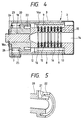
- FIG. 1 shows a condition before a key is inserted
- Fig. 6 shows the components in exploded form
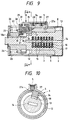
- Fig. 9 shows a condition in which a key rotor is forcibly rotated by a wrong key or the like.
- a rotor case 1 is formed into a substantially cylindrical member by coupling a cap portion 2 with a case main body 3 in an axial direction (the right side as viewed in Fig. 1 is referred to as the front side).
- a substantially cylindrical sleeve 8 is rotatably arranged inside the rotor case 1. As shown in Fig. 2, tumbler engagement grooves 9, 9 are formed on the inner surface of the sleeve 8, and a recessed cam portion 11 is formed on the outer surface thereof.
- the cam portion 11 constitutes a part of an uncoupling mechanism 10, which will be described later.
- a collar portion 12 that is opened at the cam portion 11 is formed at the rear end of the sleeve 8.
- a substantially shaft-like key rotor 13 is rotatably arranged inside the sleeve 8.
- a keyhole 14 runs through the key rotor 13 in the axial direction, and a plurality of tumbler setting grooves 15 are arranged in the key rotor 13 in the radial direction.
- Tumblers 16 are movably set in the respective tumbler setting grooves 15.
- Each tumbler 16 is urged so as to move in a direction indicated by an arrow A1 in Fig. 2 by a corresponding spring member 17, with an end portion 16a thereof being held while inserted into one of the tumbler engagement grooves 9, 9.
- the tumblers can be engaged with the sleeve 8 in a direction of rotation.
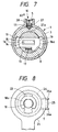
- each tumbler 16 is designed to be disengaged from the tumbler engagement groove 9 by being moved in a direction opposite to the arrow A1 upon insertion of a key (regular key) into the keyhole 14 (see Fig. 7).
- a lock lever 24 is fitted into and coupled with this lever fitting protuberance 23.
- the lock lever 24 has not only a positioning portion 25 but also a coupling portion 24a that is coupled with, e.g., a door lock mechanism.
- the lock lever 24 and hence the key rotor 13 are designed to be held in a predetermined angular position by a torsion spring 26. That is, as shown in Fig. 8, with the positioning portion 25 of the lock lever 24 and the spring hold plate 7 of the case main body 3 being aligned, the torsion spring 26 is squeezed in to cause both ends 26a, 26a of the torsion spring 26 to be retained by both sides of the positioning portion 25 and the spring hold plate 7.
- the lock lever 24 is made unreleasable by an E ring 18a attached to an end portion of the support shaft portion 18.
- the uncoupling mechanism 10 is constructed in the following manner.
- a moving element 27 is set in the moving element setting groove 4 so as to be movable in the radial directions (up and down).
- a projected fitting portion 27a that is fitted into the cam portion 11 is formed on the lower surface of the moving element 27.
- This moving element 27 is urged by springs 28 in such a direction as to be fitted into the cam portion 11.
- the moving element 27 is designed to move in a direction indicated by an arrow A2 in Figs. 1 and 2 upon rotation of the sleeve 8.
- a support piece 29 is formed in the rear of the moving element 27.
- the support piece 29 is an arc subtending the center of the key rotor 13.
- an intermediate block 30 is disposed on the rear rotor side coupling portion 21 so as to be movable in both radial and rotational directions.
- a holding groove 31 is formed in an upper portion of the intermediate block 30. The holding groove 31 retains the support piece 29 in the radial direction and allows the support piece 29 to move in the rotational direction.
- a coupling member holding recess 32 and a coupling member holding projection 33 are both lower and front portions of the intermediate block 30.
- a coupling member 34 whose movement is controlled by the uncoupling mechanism 10 is arranged so as to be movable in the radial directions while bridging between the key rotor side coupling portion 19 and the rear rotor side coupling portion 21. That is, the coupling member 34 is substantially C-shaped with an arcuate upper piece 35 and an arcuate lower piece 36 coupled through an intermediate portion 37. The intermediate portion 37 is fitted with the key rotor side coupling portion 19, and the upper piece 35 and the lower piece 36 are fitted into the coupling member holding projection 33 and the coupling member holding recess 32 of the intermediate block 30 within the rear rotor side coupling portion 21, respectively.
- the lower piece 36 of the coupling member 34 confronts both wall surfaces of the rear rotor side coupling portion 21 in the rotational direction and does not confront the release portion 22, so that the coupling member 34 is so positioned as to be engageable with the respective coupling portions 19, 21 in the rotational direction. Further, under the condition shown in Fig. 9, the lower piece 36 of the coupling member 34 confronts the release portion 22 in the rotational direction in the rear rotor side coupling portion 21. That is, the lower piece 36 is disengaged, so that the key rotor 13 is in such a release position as to be freely rotatable independently of the rear rotor 20.
- the coupling member 34 does not move to the uncoupling position, thus leaving the key rotor 13 and the rear rotor 20 coupled.
- the key rotor 13 rotates, so do the rear rotor 20 and hence the lock lever 24, which in turn unlocks the cylinder lock.
- the spring force of the torsion spring 26 causes the rear rotor 20 and the key rotor 13 to return to the original positions thereof.
- the key rotor 13 is continuously rotated, the lower piece 36 of the coupling member 34 is inserted into the release portion 22, allowing the key rotor 13 to rotate.
- the rear rotor 20 and hence the lock lever 24 do not rotate, which does not allow the cylinder lock to be unlocked. That is, even if the key rotor 13 is rotated by a wrong key or the like, the key rotor 13, the sleeve 8, and the coupling member 34 only rotate idly, thereby not allowing the cylinder lock to be unlocked nor giving any damaging force to the respective components thereof. As a result, not only the possibility of the components being broken is excluded, but also the cylinder lock can be used again.
- the key rotor 13, the sleeve 8, and the coupling member 34 only rotate idly although the key rotor is forcibly rotated by a key other than the regular key, a screwdriver, or the like. Therefore, not only the cylinder lock cannot be unlocked, but also no damaging force is applied to the components thereof such as the tumblers 16, the key rotor 13, and the sleeve 8, excluding the likelihood of these components being broken and thereby ensuring reuse of the cylinder lock.
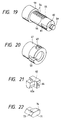
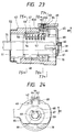
- FIG. 11 to 27 show conditions with a key 41 being inserted; Figs. 17 to 22 show the components; and Figs. 23 to 27 show conditions with the key rotor being forcibly rotated by a wrong key or the like.
- a rotor case 42 is cylindrical, and a moving member setting groove 43 is formed in an upper portion of the rotor case 42.
- a spring hold plate 44 is attached to the upper portion of the moving member setting groove 43.
- an arcuate groove 45 is formed in the rear of the rotor case 42 (on the right side as viewed in Figs. 11 and 17) with retaining portions 45a, 45a formed on both sides of the groove 45.
- a sloped V-shaped original position engagement recess 46 is formed in a position about 90° shifted in a circumferential direction with respect to the moving member setting groove 43.
- a substantially cylindrical sleeve 47 is arranged in an intermediate portion inside the rotor case 42, the portion being intermediate as viewed in the axial direction.
- Tumbler engagement grooves 48, 48 are formed on the inner surface of the sleeve 47 so as to confront each other, and as shown in Fig. 20, not only a recessed cam portion 49 is formed on the outer surface thereof, but also a moving block setting hole 50 is formed in a position about 90° shifted in the circumferential direction with respect to the cam portion 49 so as to pass through in the radial direction.
- the respective tumblers 56, 57 have ends thereof projected from the tumbler setting grooves 54, 55 and inserted into the tumbler engagement groove 48 of the sleeve 47 (see Figs. 25 and 26), making the respective tumblers 56, 57 engageable with the sleeve 47 in the rotational direction.
- the respective tumblers 56, 57 are moved in such a direction as to be set in the tumbler setting grooves 54, 55, thereby being released from the tumbler engagement groove 48 (see Figs. 13 and 14).
- a shaft portion 59 is projected from the rear of the key rotor 51.
- a lock lever engagement recess 60 is formed on top of the root of the shaft portion 59 as shown also in Fig. 19.
- an engagement recess 61 is formed on the outer surface on the rear side of the key rotor 51 so as to confront the original position engagement recess 46.
- a moving member 62 shown in Fig. 21 is arranged in the moving member setting groove 43 of the rotor case 42 so as to be movable in a circumferential direction (up and down as viewed in Fig. 11).
- the moving member 62 is urged toward the sleeve 47 by a spring member 63 that is interposed between the moving member 62 and the spring hold plate 44 with a fitting portion 62a thereof fitted into the cam portion 49 on the sleeve side 47, and is arranged so as to bridge between the rotor case 42 and the sleeve 47.
- On the rear side of the moving member 62 is a retaining groove 64 that has openings on the rear as well as on both left and right sides (see Fig. 15).
- the moving member 62 is movable in the radial directions between a coupling position at which the fitting portion 62a is fitted into the cam portion 49 (see Figs. 11, 14, and 15) and an uncoupling position at which the fitting portion 62a comes out of the cam portion 49 as a result of the rotation of the sleeve 47 (see Figs. 23, 26, and 27).
- a lock lever 65 is attached to the shaft portion 59 of the key rotor 51 so as to be unreleasable by an E ring 66.
- a fitting hole 67 into which the shaft portion 59 is fitted is elongated in a single radial direction, and a projection 68 engageable with the lock lever engagement recess 60 on the shaft portion 59 side is formed on a part of the fitting hole 67.
- a retaining projection 69 that is retained in the retaining groove 64 of the moving member 62 is arranged integrally with the lock lever 65.
- the lock lever 65 is movable in the radial directions between an engagement position at which the projection 68 is engaged with the lock lever engagement recess 60 as shown in Figs. 11 and 12 and a disengagement position at which the projection 68 is disengaged from the lock lever engagement recess 60 as shown in Figs. 23 and 24.
- the lock lever 65 is rotatable integrally with the key rotor 51 with the projection 68 engaged with the lock lever engagement recess 60.
- a return spring 70 which is a torsion spring, is provided in an outer circumferential portion in the rear of the key rotor 51. This return spring 70 gives a force for urging the lock lever 65 and the key rotor 51 to an original position when the lock lever 65 and the key rotor 51 are rotated from the original position.
- a moving block 71 shown in Fig. 22 is movably arranged in the moving block setting hole 50 of the sleeve 47.
- This moving block 71 is urged toward the rotor case 42 by a spring member 72, and holds the sleeve 47 in the original position with a first engagement portion 73 thereof engaged with the original position engagement recess 46 (see Figs. 14 to 16).
- This moving block 71 has a second engagement portion 74 on the key rotor 51 side.
- reference numeral 75 in Figs. 23, 25 to 27 denotes a wrong key as a key other than the regular key.
- the moving member 62 is set to the coupling position, but also the lock lever 65 is set to the engagement position, so that the projection 68 of the lock lever 65 is engaged with the lock lever engagement recess 60 of the key rotor 51 (see Figs. 11 and 12). Therefore, the key rotor 51 and the lock lever 65 are rotatable integrally with each other.
- the engagement groove 64 of the moving member 62 is in communication with the groove 45 of the rotor case 42 (see Fig. 15).
- the moving block 71 bridges between the sleeve 47 and the rotor case 42 while engaged with the original position engagement recess 46 of the rotor case 42. As a result of the engagement, the sleeve 47 is held in the original position.
- the moving member 62 When the sleeve 47 is rotated, the moving member 62 is caused to move to the uncoupling position, which is up, by the slopes of the cam portion 49 arranged in the sleeve 47 (see an arrow B1 in Figs. 23 and 26) and, in association therewith, the lock lever 65 is moved to the disengagement position, which is up (see the arrow B1 in Fig. 24), disengaging the projection 68 of the lock lever 65 from the lock lever engagement recess 60 of the key rotor 51.
- the moving block 71 is moved toward the key rotor 51 by the slopes of the original position engagement recess 46 (see an arrow B2 in Figs. 26 and 27), which disengages the moving block 71 from the rotor case 42 and in turn engages the moving block 71 with the engagement recess 61 of the key rotor 51.
- the key rotor 51 and the sleeve 47 are rotated integrally with each other, but the lock lever 65 is not rotated.
- the cylinder lock is not unlocked. That is, even if the key rotor is forcibly rotated by the wrong key or the like, the key rotor 51 and the sleeve 47 only rotate idly, which neither unlocks the cylinder lock nor gives any damaging force to the components thereof, thereby excluding the possibility of the components being broken and allowing the cylinder lock to be used again.
- the cylinder lock according to the second embodiment is provided as only rotating the key rotor 51 and the sleeve 47 idly and not rotating the lock lever 65 when the key rotor 51 is forcibly rotated by the insertion of the wrong key 75 or the like. Therefore, not only the cylinder lock is not unlocked, but also no damaging force is applied to the components thereof. As a result, there is no likelihood that the components will be broken, and the cylinder lock can therefore be used again.
- the cylinder lock according to the second embodiment is further advantageous in preventing the cylinder lock from becoming large in the axial direction.
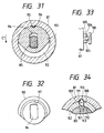
- FIG. 28 to 34 show conditions before a key is inserted as well as components; Figs. 35 and 36 show conditions with a regular key inserted; and Fig. 37 shows a condition when the key rotor is forcibly rotated by a wrong key or the like.
- a cylindrical sleeve 82 is rotatably arranged inside a cylindrical rotor case 81.
- a key rotor 83 is rotatably arranged inside the sleeve 82.
- the key rotor 83 is provided with a cover 84 so as not to be released frontward.
- a shaft portion 85 in the rear (on the right portion as viewed in Fig. 28) of the key rotor 83 is projected rearward from a shaft insertion hole 86.
- the shaft portion 85 is substantially oval in section (see Fig. 31), and has a projection 87 at the rear end thereof.
- a lock lever engagement recess 88 (see Fig. 30) is formed on the projection 87.
- Tumbler engagement grooves 89, 89 are formed on the inner surface of the sleeve 82 so as to confront each other. Not only a keyhole (not shown) is formed in the key rotor 83 in the axial direction, but also a plurality of radially extending tumbler setting grooves 91 are formed.
- the respective tumbler setting grooves 91 have tumblers 92 movably set therein, and the respective tumblers 92 are urged so as to move in a single direction by not shown corresponding springs.
- a recess 95 is formed on an upper portion of the rear rotor 93.
- a cam portion 96 arranged at the rear end portion of the sleeve 82 is fitted into this recess 95.
- an arcuate retaining groove 97 is formed on the rear side of the rear rotor 93.
- a retaining piece 104 is formed below the fitting hole 100 by cutting a piece and raising the cut piece frontward. This retaining piece 104 is inserted between stopper projections 105, 105 arranged on the rear wall 81a of the rotor case 81 (see Fig. 33).
- a return spring 106 which is a torsion spring, is arranged around the shaft portion 85 of the key rotor 83. This return spring 106 imparts a force for urging the key rotor 83 and the lock lever 98 to an original position when the key rotor 83 and the lock lever 98 are rotated from the original position. Further, the lock lever 98 is urged upward as viewed in Fig. 28 by this return spring 106.
- the lock lever 98 under the pre-insertion condition, the lock lever 98 is set to a disengagement position, which is up, and the rear rotor 93 engaged with the lock lever 98 is set to an uncoupling position, which is up. Under such condition, the projection 101 of the lock lever 98 is disengaged from the lock lever engagement recess 88 of the key rotor 83 (see Fig. 30).
- a moving block setting hole 107 is formed in the sleeve 82, and a moving block 108 is set in the moving block setting hole 107 so as to be movable in the radial directions.
- This moving block 108 is urged toward the rotor case 81 by a pin-like spring member 109 that is arranged so as to pass through the moving block 108.
- the moving block 108 By the moving block 108 being brought into engagement with the original position engagement recess 111 of the rotor case 81, the moving block 108 bridge between the sleeve 82 and the rotor case 81, so that the sleeve 82 is held in the original position by the engagement.
- the rear rotor 93 is caused to move to the coupling position (see Fig. 35), which is down, by the cam portion 96 arranged in the sleeve 82 and, in association therewith, the lock lever 98 is moved to the engagement position (see Figs. 35 and 36), thereby engaging the projection 101 of the lock lever 98 with the lock lever engagement recess 88 of the key rotor 83.
- the retaining piece 104 is displaced downward from the stopper projections 105, 105, which in turn allows the lock lever 98 to rotate.
- the key rotor 83 and the lock lever 98 are rotated integrally with each other, thus allowing the cylinder lock to be unlocked.
- the range of rotation of the lock lever 98 is regulated by the hole 103 of the rotor case 81.
- the sleeve 82 since the sleeve 82 is held in the original position by the moving block 108 in this case, the sleeve 82 does not rotate although the key rotor 83, the rear rotor 93, and the lock lever 98 are rotated integrally with one another.
- a key other than the regular key e.g., a wrong key (not shown) is inserted into the keyhole to forcibly rotate the key rotor.
- the tumblers 92 are brought into engagement with the tumbler engagement groove 89, so that the key rotor 83, the sleeve 82, and the rear rotor 93 rotate integrally with one another.
- the sleeve 82 and the rear rotor 93 rotate integrally, the relative positions of the sleeve 82 and the rear rotor 93 remain unchanged.
- the rear rotor 93 remains in the disengagement position, and the lock lever 98 remains in the disengagement position as well.
- the lock lever 98 does not rotate in this case, thereby not allowing the cylinder lock to be unlocked. That is, even if the key rotor is forcibly rotated by a wrong key or the like, the key rotor 83, the sleeve 82, and the rear rotor 93 only rotate idly, thereby neither allowing the cylinder lock to be unlocked, nor allowing a damaging force to be applied to the components thereof. Hence, the possibility of the components being broken is excluded, and the cylinder lock can therefore be used again.
- the key rotor 83, the sleeve 82, and the rear rotor 93 may, in some cases, be out of the original position also in the third embodiment.
- the cylinder lock according to the third embodiment is provided as only rotating the key rotor 83, the sleeve 82, and the rear rotor 93 idly and not rotating the lock lever 98 when the key rotor 83 is forcibly rotated by the insertion of a wrong key or the like. Therefore, not only the cylinder lock is not unlocked, but also no damaging force is applied to the components thereof. As a result, there is no likelihood that the components will be broken, and the cylinder lock can therefore be used again.
- the cylinder lock according to the third embodiment is also provided as holding the sleeve 82 in the original position by arranging the moving block 108 in the sleeve 82 and engaging the moving block 108 with the original position engagement recess 111 of the rotor case 81, as well as causing the moving block 108 to be engaged with the key rotor 83 to thereby rotate the sleeve 82 and the key rotor 83 integrally with each other if the sleeve 82 and the key rotor 83 are rotated by a wrong key or the like. Therefore, the rotation of the sleeve 82 is prohibited at the time of legally unlocking and locking the cylinder lock.
- the original position of the sleeve 82 and the key rotor 83 can be identified.
- the cylinder lock according to the third embodiment is further advantageous in preventing the cylinder lock from becoming large in the axial direction.
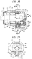
- FIG. 38 to 41 show conditions before the regular key 41 is inserted;
- Fig. 42 shows a main portion of major components in exploded perspective form; and
- Figs. 43 to 46 show conditions in which the key rotor is forcibly rotated by a wrong key or the like.
- the moving member setting groove 43 and the arcuate groove 45 having the retaining portions 45a are formed on a lower portion in the drawings.
- the recessed original position engagement recess 46 having slopes is formed in a position about 90° shifted in the circumferential direction with respect to the moving member setting groove 43.
- On the outer surface on the rear side of the key rotor 51 arranged inside the sleeve 47 is the engagement recess 61 as shown in Fig. 42.
- a coupling member engagement recess 121 is also formed in a position about 90° shifted in the circumferential direction with respect to the engagement recess 61.
- the moving member setting groove 43 has a moving member 122 arranged so as to be movable in the circumferential direction (up and down as viewed in Fig. 38).
- the moving member 122 is urged toward the sleeve 47 by the spring member 63 interposed between the moving member 122 and a spring receiving portion 43a.
- a fitting portion 122a is fitted with the cam portion 49 on the sleeve 47 side. That is, the moving member 122 is arranged so as to bridge between the rotor case 42 and the sleeve 47.
- On the rear side of the moving member 122 is a retaining groove 123 that is opened on the rear as well as both left and right sides (see Fig. 41).
- This moving member 122 is designed to be movable in the radial directions between the coupling position at which the fitting portion 122a is fitted into the cam portion 49 (see Figs. 38, 40, and 41) and the uncoupling position at which the fitting portion 122a is out of the cam portion 49 (see Figs. 43, 45, and 46).
- a lock lever 124 is attached to the shaft portion 59 of the key rotor 51 so as to be unreleasable by the E ring 66.
- a fitting hole 125 of the lock lever 124 which is fitted with the shaft portion 59 is formed into a circular member so as to correspond to the shaft portion 59.
- a retaining piece 126 is formed on the lock lever 124 so as to face downward.
- the coupling member 127 is movable in the radial directions between the engagement position at which the engagement projection 130 is engaged with the coupling member engagement recess 121 as shown in Figs. 38 and 39 and the disengagement position at which the engagement projection 130 is disengaged from the coupling member engagement recess 121 as shown in Figs. 43 and 44, so that the key rotor 51 and the lock lever 124 can be rotated integrally with each other with the engagement projection 130 engaged with the coupling member engagement recess 121.
- the moving member 122 is set to the coupling position, but also the coupling member 127 is set to the engagement position, and the engagement projection portion 130 of the coupling member 127 is engaged with the coupling member engagement recess 121 of the key rotor 51 (see Figs. 38 and 39), so that the key rotor 51 is readily engageable with the lock lever 124 through the coupling member 127. Therefore, the key rotor 51 and the lock lever 124 are rotatable integrally with each other.
- the retaining groove 123 of the moving member 122 is in communication with the groove 45 of the rotor case 42 (see Fig. 41).
- the moving block 71 bridges between the sleeve 47 and the rotor case 42 while engaged with the original position engagement recess 46 of the rotor case 42. As a result of the engagement, the sleeve 47 is held in the original position.
- the key rotor 51 is made freely rotatable with respect to the sleeve 47.
- the key rotor 51 is rotated with respect to the sleeve 47 and hence the rotor case 42, which in turn rotates the lock lever 124 that is engaged with the key rotor 51 through the coupling member 127 integrally, thereby allowing the cylinder lock to be unlocked.
- the moving member 122 When the sleeve 47 rotates, the moving member 122 is moved to the uncoupling position, which is down, by the slopes of the cam portion 49 arranged in the sleeve 47 (see an arrow D1 in Figs. 43 and 45) and, in association therewith, the coupling member 127 is moved to the disengagement position, which is down (see the arrow D1 in Fig. 44), disengaging the engagement projection 130 of the coupling member 127 from the coupling member engagement recess 121 of the key rotor 51.
- the moving block 71 is moved toward the key rotor 51 by the slopes of the original position engagement recess 46 (see an arrow D2 in Figs. 45 and 46), which disengages the moving block 71 from the rotor case 42 and in turn engages the moving block 71 with the engagement recess 61 of the key rotor 51.
- the key rotor 51 and the sleeve 47 rotate integrally with each other, but the lock lever 124 is not rotated.
- the cylinder lock is not unlocked. That is, even if the key rotor is forcibly rotated by a wrong key or the like, the key rotor 51 and the sleeve 47 only rotate idly, which neither unlocks the cylinder lock nor gives any damaging force to the components thereof, thereby excluding the possibility of the components being broken and allowing the cylinder lock to be used again.
- the key rotor 51 and the sleeve 47 may, in some cases, be out of the original position.
- the cylinder lock according to the fourth embodiment can provide not only advantages similar to those of the second embodiment, but also the following advantages. Since not only the retaining piece 126 of the lock lever 124 is fitted with the fitting cylinder portion 128 of the coupling member 127 but also the engagement projection 130 of the coupling member 127 is engaged with the coupling member engagement recess 121 of the key rotor 51, a sufficiently large margin is given for the engagement of the engagement projection 130 with the coupling member engagement recess 121 in the axial direction, which in turn ensures sufficient mechanical strength for these engagement portions.
- the projection 68 arranged on the fitting hole 67 portion of the lock lever 65 is engaged with the lock lever engagement recess 60 arranged on the shaft portion 59 of the key rotor 51. Therefore, only a margin as much as the thickness of the lock lever 65 can be provided for the engagement of the projection 68 in the axial direction, which thus makes it difficult to ensure a sufficient strength of the projection 68.
- the cylinder locks according to the present invention are provided as only rotating the key rotor and the sleeve idly and not rotating the lock lever even if a key other than the regular key, a screwdriver, or the like is inserted thereinto to forcibly rotate the key rotor. Therefore, not only the cylinder locks cannot be unlocked, but also no damaging force is applied to the components thereof. Hence, the possibility of the components being broken is excluded and the cylinder locks can thereby be used again. In addition, the absence of axially moving members contributes to preventing the cylinder locks from growing in size in the axial direction.
- the cylinder lock according to the present invention is provided as holding the sleeve in the original position by arranging the moving block in the sleeve and allowing the moving block to be engaged with the original position engagement recess of the rotor case, and as rotating the sleeve and the key rotor integrally with each other by causing the moving block to be engaged with the key rotor if the sleeve and the key rotor are rotated by a wrong key or the like. Therefore, the rotation of the sleeve can be prohibited at the time of regularly unlocking and locking the cylinder lock. In addition, the position of the sleeve and the key rotor can be identified.
Landscapes
- Lock And Its Accessories (AREA)
Applications Claiming Priority (9)
| Application Number | Priority Date | Filing Date | Title |
|---|---|---|---|
| JP29996593 | 1993-11-30 | ||
| JP299965/93 | 1993-11-30 | ||
| JP29996593 | 1993-11-30 | ||
| JP8452494 | 1994-04-22 | ||
| JP8452494 | 1994-04-22 | ||
| JP84524/94 | 1994-04-22 | ||
| JP26025294 | 1994-10-25 | ||
| JP260252/94 | 1994-10-25 | ||
| JP26025294A JPH084378A (ja) | 1993-11-30 | 1994-10-25 | シリンダ錠装置 |
Publications (2)
| Publication Number | Publication Date |
|---|---|
| EP0659961A1 true EP0659961A1 (fr) | 1995-06-28 |
| EP0659961B1 EP0659961B1 (fr) | 2000-04-19 |
Family
ID=27304572
Family Applications (1)
| Application Number | Title | Priority Date | Filing Date |
|---|---|---|---|
| EP19940118897 Expired - Lifetime EP0659961B1 (fr) | 1993-11-30 | 1994-11-30 | Serrure cylindrique |
Country Status (4)
| Country | Link |
|---|---|
| US (1) | US5577409A (fr) |
| EP (1) | EP0659961B1 (fr) |
| JP (1) | JPH084378A (fr) |
| DE (1) | DE69424026T2 (fr) |
Cited By (4)
| Publication number | Priority date | Publication date | Assignee | Title |
|---|---|---|---|---|
| EP0769598A1 (fr) * | 1995-10-18 | 1997-04-23 | Valeo Securite Habitacle | Verrou du type à rotor débrayable |
| EP0769597A1 (fr) * | 1995-10-18 | 1997-04-23 | Valeo Securite Habitacle | Verrou du type à rotor débrayable |
| EP0833023A3 (fr) * | 1996-09-25 | 1998-09-16 | VALEO GmbH & Co Schliesssysteme KG | Serrure cylindrique avec une embrayage de surcharge |
| WO1999063187A1 (fr) * | 1998-05-30 | 1999-12-09 | Huf Hülsbeck & Fürst Gmbh & Co. Kg | Dispositif de fermeture pour fonctions de fermeture pouvant etre executees notamment sur des vehicules |
Families Citing this family (23)
| Publication number | Priority date | Publication date | Assignee | Title |
|---|---|---|---|---|
| DE4412609A1 (de) * | 1994-04-13 | 1995-10-19 | Huelsbeck & Fuerst | Verschlußvorrichtung für insbesondere an Kraftfahrzeugen vollziehbare Schließfunktionen |
| US5765417A (en) * | 1996-04-03 | 1998-06-16 | U-Shin Ltd. | Free wheel lock cylinder |
| FR2748513B1 (fr) * | 1996-05-10 | 1998-06-26 | Valeo Securite Habitacle | Verrou a debrayage axial pour un mecanisme de serrure de vehicule automobile |
| US5934117A (en) * | 1997-09-24 | 1999-08-10 | Shen; Mu-Lin | Lock with a clutching outer handle |
| US6523382B1 (en) * | 1998-09-08 | 2003-02-25 | Strattec Security Corporation | Free wheeling lock assembly |
| US6058751A (en) * | 1998-09-08 | 2000-05-09 | Strattec Security Corporation | Free-wheeling lock |
| US6527308B2 (en) * | 2000-11-01 | 2003-03-04 | S.P.E.P. Acquisitions Corp | Spring-loaded camlock |
| US6553793B1 (en) * | 2002-05-16 | 2003-04-29 | Tian-Yuan Chen | Motorcycle disc brake lock |
| US6711924B2 (en) * | 2002-06-18 | 2004-03-30 | Strattec Security Corporation | Freewheeling lock apparatus and method |
| US6978645B2 (en) * | 2003-06-23 | 2005-12-27 | Strattec Security Corporation | Freewheeling lock apparatus and method |
| US20050115288A1 (en) * | 2003-12-02 | 2005-06-02 | Burmahln Jedediah A. | Adjustable locking mechanism |
| EP1896676A4 (fr) * | 2005-06-16 | 2014-07-02 | Moshe Dolev | Cylindre a barillet avec came modifiee |
| JP4746467B2 (ja) * | 2006-04-10 | 2011-08-10 | 株式会社東海理化電機製作所 | キーシリンダ |
| US8522584B2 (en) * | 2006-06-14 | 2013-09-03 | Moshe Dolev | High-security rotating bolt lock |
| US7357010B1 (en) * | 2006-11-21 | 2008-04-15 | Taiwan Fu Hsing Industrial Co., Ltd. | Plug assembly for a door lock |
| JP2008255726A (ja) * | 2007-04-06 | 2008-10-23 | Tokai Rika Co Ltd | シリンダ錠装置 |
| JP5005459B2 (ja) * | 2007-07-30 | 2012-08-22 | 株式会社東海理化電機製作所 | シリンダ錠及びこれを備えた解錠装置 |
| JP5014914B2 (ja) | 2007-08-08 | 2012-08-29 | 株式会社東海理化電機製作所 | シリンダ錠装置 |
| JP4907489B2 (ja) * | 2007-10-25 | 2012-03-28 | 株式会社東海理化電機製作所 | シリンダ錠及びこれを備えた解錠装置 |
| JP2009281005A (ja) * | 2008-05-20 | 2009-12-03 | Tokai Rika Co Ltd | シリンダ錠装置 |
| US20150211257A1 (en) * | 2014-01-28 | 2015-07-30 | Vsi, Llc | Free-wheel lock and assembly |
| JP2015227584A (ja) * | 2014-06-02 | 2015-12-17 | 株式会社東海理化電機製作所 | シリンダ錠装置 |
| TWM521102U (zh) * | 2015-08-28 | 2016-05-01 | Lintex Co Ltd | 鎖具 |
Citations (3)
| Publication number | Priority date | Publication date | Assignee | Title |
|---|---|---|---|---|
| FR2583813A1 (fr) * | 1985-06-19 | 1986-12-26 | Neiman Sa | Verrou a rotor cylindrique commandant un doigt d'entrainement |
| EP0341132A1 (fr) * | 1988-05-04 | 1989-11-08 | Valeo Neiman | Verrou à rotor débrayable |
| EP0444972A1 (fr) * | 1990-01-29 | 1991-09-04 | Vachette | Verrou comprenant un stator et un rotor monté libre en rotation dans le stator |
Family Cites Families (8)
| Publication number | Priority date | Publication date | Assignee | Title |
|---|---|---|---|---|
| US3410123A (en) * | 1966-09-12 | 1968-11-12 | Briggs & Stratton Corp | Disconnecting side bar lock |
| US3992907A (en) * | 1975-03-27 | 1976-11-23 | Aksel Pilvet | Axial pin tumber lock with engageable clutch member |
| FR2557623B1 (fr) * | 1983-12-28 | 1986-04-25 | Neiman Sa | Dispositif de commande debrayable d'un mecanisme de serrure a condamnation |
| FR2642463B1 (fr) * | 1989-01-30 | 1991-03-29 | Neiman Sa | Serrure debrayable a stator rotatif |
| GB2228523B (en) * | 1989-02-23 | 1993-04-14 | Land Rover Uk Ltd | A locking mechanism |
| US5265453A (en) * | 1990-11-30 | 1993-11-30 | Alpha Corporation | Cylinder lock |
| DE4122414C1 (de) * | 1991-07-06 | 1992-12-03 | Huelsbeck & Fuerst | Schließzylinder |
| FR2691496B1 (fr) * | 1992-05-20 | 1999-12-03 | Valeo Securite Habitacle | Verrou a rotor debrayable, notamment pour serrure de vehicule automobile. |
-
1994
- 1994-10-25 JP JP26025294A patent/JPH084378A/ja active Pending
- 1994-11-29 US US08/348,830 patent/US5577409A/en not_active Expired - Fee Related
- 1994-11-30 EP EP19940118897 patent/EP0659961B1/fr not_active Expired - Lifetime
- 1994-11-30 DE DE69424026T patent/DE69424026T2/de not_active Expired - Fee Related
Patent Citations (3)
| Publication number | Priority date | Publication date | Assignee | Title |
|---|---|---|---|---|
| FR2583813A1 (fr) * | 1985-06-19 | 1986-12-26 | Neiman Sa | Verrou a rotor cylindrique commandant un doigt d'entrainement |
| EP0341132A1 (fr) * | 1988-05-04 | 1989-11-08 | Valeo Neiman | Verrou à rotor débrayable |
| EP0444972A1 (fr) * | 1990-01-29 | 1991-09-04 | Vachette | Verrou comprenant un stator et un rotor monté libre en rotation dans le stator |
Cited By (8)
| Publication number | Priority date | Publication date | Assignee | Title |
|---|---|---|---|---|
| EP0769598A1 (fr) * | 1995-10-18 | 1997-04-23 | Valeo Securite Habitacle | Verrou du type à rotor débrayable |
| EP0769597A1 (fr) * | 1995-10-18 | 1997-04-23 | Valeo Securite Habitacle | Verrou du type à rotor débrayable |
| FR2740163A1 (fr) * | 1995-10-18 | 1997-04-25 | Valeo Securite Habitacle | Verrou du type a rotor debrayable |
| FR2740164A1 (fr) * | 1995-10-18 | 1997-04-25 | Valeo Securite Habitacle | Verrou a rotor debrayable |
| EP0833023A3 (fr) * | 1996-09-25 | 1998-09-16 | VALEO GmbH & Co Schliesssysteme KG | Serrure cylindrique avec une embrayage de surcharge |
| WO1999063187A1 (fr) * | 1998-05-30 | 1999-12-09 | Huf Hülsbeck & Fürst Gmbh & Co. Kg | Dispositif de fermeture pour fonctions de fermeture pouvant etre executees notamment sur des vehicules |
| US6439016B1 (en) | 1998-05-30 | 2002-08-27 | Huf Hülsbeck & Fürst GmbH & Co., KG | Closing device for closing functions in vehicles in particular |
| CZ298358B6 (cs) * | 1998-05-30 | 2007-09-05 | Huf Hülsbeck & Fürst Gmbh & Co. Kg | Uzavírací zarízení, zejména pro vykonávání a ovládání uzavíracích funkcí na vozidlech |
Also Published As
| Publication number | Publication date |
|---|---|
| US5577409A (en) | 1996-11-26 |
| DE69424026T2 (de) | 2000-09-14 |
| EP0659961B1 (fr) | 2000-04-19 |
| JPH084378A (ja) | 1996-01-09 |
| DE69424026D1 (de) | 2000-05-25 |
Similar Documents
| Publication | Publication Date | Title |
|---|---|---|
| US5577409A (en) | Cylinder lock | |
| US4885923A (en) | Combination lock | |
| US6578396B2 (en) | Removable cylindrical lock core | |
| US6382006B1 (en) | Removable cylindrical lock core | |
| US5431034A (en) | Cylinder lock with removable and replaceable key plug | |
| EP0675248B1 (fr) | Dispositif de serrure cylindrique résistant au déverrouillage non autorisé | |
| US6523382B1 (en) | Free wheeling lock assembly | |
| US4142388A (en) | Tumbler wheels for combination locks | |
| US7536887B2 (en) | Cylinder lock | |
| US4416129A (en) | Cylinder lock with key removable plug | |
| KR20020000646A (ko) | 도어 록킹 장치 | |
| JPH10500744A (ja) | とくに自動車において実行可能な閉鎖機能のための鎖錠装置 | |
| US5402660A (en) | Axial tumbler cylinder lock and key | |
| US4233913A (en) | Safe door | |
| US3541820A (en) | Breechlock core and knob | |
| CA1172867A (fr) | Serrures a combinaison | |
| US5402662A (en) | Cylindrical lock and key therefor | |
| US6003351A (en) | Structure for a mortise lock | |
| EP1149220A1 (fr) | Ensemble barillet de serrure | |
| US7406847B2 (en) | Cylinder lock | |
| JPH0252752B2 (fr) | ||
| JP2881103B2 (ja) | シリンダ錠装置 | |
| JPH07229332A (ja) | 内筒交換式のシリンダ錠 | |
| JP2894943B2 (ja) | シリンダ錠装置 | |
| AU704192B2 (en) | Locks and keys |
Legal Events
| Date | Code | Title | Description |
|---|---|---|---|
| PUAI | Public reference made under article 153(3) epc to a published international application that has entered the european phase |
Free format text: ORIGINAL CODE: 0009012 |
|
| AK | Designated contracting states |
Kind code of ref document: A1 Designated state(s): DE FR GB |
|
| 17P | Request for examination filed |
Effective date: 19950810 |
|
| 17Q | First examination report despatched |
Effective date: 19961223 |
|
| GRAG | Despatch of communication of intention to grant |
Free format text: ORIGINAL CODE: EPIDOS AGRA |
|
| RAP1 | Party data changed (applicant data changed or rights of an application transferred) |
Owner name: KABUSHIKI KAISHA TOKAI RIKA DENKI SEISAKUSHO |
|
| GRAG | Despatch of communication of intention to grant |
Free format text: ORIGINAL CODE: EPIDOS AGRA |
|
| GRAH | Despatch of communication of intention to grant a patent |
Free format text: ORIGINAL CODE: EPIDOS IGRA |
|
| GRAH | Despatch of communication of intention to grant a patent |
Free format text: ORIGINAL CODE: EPIDOS IGRA |
|
| GRAA | (expected) grant |
Free format text: ORIGINAL CODE: 0009210 |
|
| AK | Designated contracting states |
Kind code of ref document: B1 Designated state(s): DE FR GB |
|
| REF | Corresponds to: |
Ref document number: 69424026 Country of ref document: DE Date of ref document: 20000525 |
|
| ET | Fr: translation filed | ||
| PG25 | Lapsed in a contracting state [announced via postgrant information from national office to epo] |
Ref country code: GB Free format text: LAPSE BECAUSE OF NON-PAYMENT OF DUE FEES Effective date: 20001130 |
|
| PLBE | No opposition filed within time limit |
Free format text: ORIGINAL CODE: 0009261 |
|
| STAA | Information on the status of an ep patent application or granted ep patent |
Free format text: STATUS: NO OPPOSITION FILED WITHIN TIME LIMIT |
|
| 26N | No opposition filed | ||
| GBPC | Gb: european patent ceased through non-payment of renewal fee |
Effective date: 20001130 |
|
| PG25 | Lapsed in a contracting state [announced via postgrant information from national office to epo] |
Ref country code: FR Free format text: LAPSE BECAUSE OF NON-PAYMENT OF DUE FEES Effective date: 20010731 |
|
| PG25 | Lapsed in a contracting state [announced via postgrant information from national office to epo] |
Ref country code: DE Free format text: LAPSE BECAUSE OF NON-PAYMENT OF DUE FEES Effective date: 20010801 |
|
| REG | Reference to a national code |
Ref country code: FR Ref legal event code: ST |