EP0659982A1 - Sequentieller Drehschieber mit doppeltwirkender Steuerung - Google Patents
Sequentieller Drehschieber mit doppeltwirkender Steuerung Download PDFInfo
- Publication number
- EP0659982A1 EP0659982A1 EP94100605A EP94100605A EP0659982A1 EP 0659982 A1 EP0659982 A1 EP 0659982A1 EP 94100605 A EP94100605 A EP 94100605A EP 94100605 A EP94100605 A EP 94100605A EP 0659982 A1 EP0659982 A1 EP 0659982A1
- Authority
- EP
- European Patent Office
- Prior art keywords
- valve shaft
- jacket
- combustion chamber
- cylindrical
- openings
- Prior art date
- Legal status (The legal status is an assumption and is not a legal conclusion. Google has not performed a legal analysis and makes no representation as to the accuracy of the status listed.)
- Granted
Links
- 238000009826 distribution Methods 0.000 title claims abstract description 25
- 230000000694 effects Effects 0.000 title claims description 22
- 238000002485 combustion reaction Methods 0.000 claims abstract description 49
- 210000003027 ear inner Anatomy 0.000 claims abstract description 47
- 239000012530 fluid Substances 0.000 claims abstract description 46
- 239000007789 gas Substances 0.000 claims abstract description 34
- 230000004888 barrier function Effects 0.000 claims abstract description 23
- 230000006835 compression Effects 0.000 claims abstract description 13
- 238000007906 compression Methods 0.000 claims abstract description 13
- 238000012546 transfer Methods 0.000 claims abstract description 6
- 238000004891 communication Methods 0.000 claims description 14
- 239000000314 lubricant Substances 0.000 claims description 10
- 238000007789 sealing Methods 0.000 claims description 10
- 238000001816 cooling Methods 0.000 claims description 6
- 230000001050 lubricating effect Effects 0.000 claims description 6
- XLYOFNOQVPJJNP-UHFFFAOYSA-N water Substances O XLYOFNOQVPJJNP-UHFFFAOYSA-N 0.000 claims description 5
- 230000001276 controlling effect Effects 0.000 claims description 3
- 230000001105 regulatory effect Effects 0.000 claims description 2
- 239000010687 lubricating oil Substances 0.000 abstract description 4
- 238000004880 explosion Methods 0.000 abstract description 3
- 239000003921 oil Substances 0.000 description 24
- 238000005461 lubrication Methods 0.000 description 9
- 238000010276 construction Methods 0.000 description 7
- 239000000919 ceramic Substances 0.000 description 4
- 230000033001 locomotion Effects 0.000 description 4
- 230000006872 improvement Effects 0.000 description 3
- 230000000712 assembly Effects 0.000 description 2
- 238000000429 assembly Methods 0.000 description 2
- 238000013461 design Methods 0.000 description 2
- 238000004519 manufacturing process Methods 0.000 description 2
- 229910045601 alloy Inorganic materials 0.000 description 1
- 239000000956 alloy Substances 0.000 description 1
- 230000005540 biological transmission Effects 0.000 description 1
- 239000010724 circulating oil Substances 0.000 description 1
- 238000007667 floating Methods 0.000 description 1
- 210000003128 head Anatomy 0.000 description 1
- 230000017525 heat dissipation Effects 0.000 description 1
- 238000003780 insertion Methods 0.000 description 1
- 230000037431 insertion Effects 0.000 description 1
- 230000001788 irregular Effects 0.000 description 1
- 238000003754 machining Methods 0.000 description 1
- 230000014759 maintenance of location Effects 0.000 description 1
- 239000000463 material Substances 0.000 description 1
- 230000007246 mechanism Effects 0.000 description 1
- 239000002184 metal Substances 0.000 description 1
- CKFGINPQOCXMAZ-UHFFFAOYSA-N methanediol Chemical compound OCO CKFGINPQOCXMAZ-UHFFFAOYSA-N 0.000 description 1
- 238000012986 modification Methods 0.000 description 1
- 230000004048 modification Effects 0.000 description 1
- 239000002245 particle Substances 0.000 description 1
- 230000021715 photosynthesis, light harvesting Effects 0.000 description 1
- 230000009467 reduction Effects 0.000 description 1
Images

Classifications
-
- F—MECHANICAL ENGINEERING; LIGHTING; HEATING; WEAPONS; BLASTING
- F01—MACHINES OR ENGINES IN GENERAL; ENGINE PLANTS IN GENERAL; STEAM ENGINES
- F01L—CYCLICALLY OPERATING VALVES FOR MACHINES OR ENGINES
- F01L1/00—Valve-gear or valve arrangements, e.g. lift-valve gear
- F01L1/34—Valve-gear or valve arrangements, e.g. lift-valve gear characterised by the provision of means for changing the timing of the valves without changing the duration of opening and without affecting the magnitude of the valve lift
-
- F—MECHANICAL ENGINEERING; LIGHTING; HEATING; WEAPONS; BLASTING
- F01—MACHINES OR ENGINES IN GENERAL; ENGINE PLANTS IN GENERAL; STEAM ENGINES
- F01L—CYCLICALLY OPERATING VALVES FOR MACHINES OR ENGINES
- F01L13/00—Modifications of valve-gear to facilitate reversing, braking, starting, changing compression ratio, or other specific operations
- F01L13/0015—Modifications of valve-gear to facilitate reversing, braking, starting, changing compression ratio, or other specific operations for optimising engine performances by modifying valve lift according to various working parameters, e.g. rotational speed, load, torque
-
- F—MECHANICAL ENGINEERING; LIGHTING; HEATING; WEAPONS; BLASTING
- F01—MACHINES OR ENGINES IN GENERAL; ENGINE PLANTS IN GENERAL; STEAM ENGINES
- F01L—CYCLICALLY OPERATING VALVES FOR MACHINES OR ENGINES
- F01L7/00—Rotary or oscillatory slide valve-gear or valve arrangements
- F01L7/02—Rotary or oscillatory slide valve-gear or valve arrangements with cylindrical, sleeve, or part-annularly shaped valves
- F01L7/026—Rotary or oscillatory slide valve-gear or valve arrangements with cylindrical, sleeve, or part-annularly shaped valves with two or more rotary valves, their rotational axes being parallel, e.g. 4-stroke
-
- F—MECHANICAL ENGINEERING; LIGHTING; HEATING; WEAPONS; BLASTING
- F01—MACHINES OR ENGINES IN GENERAL; ENGINE PLANTS IN GENERAL; STEAM ENGINES
- F01L—CYCLICALLY OPERATING VALVES FOR MACHINES OR ENGINES
- F01L7/00—Rotary or oscillatory slide valve-gear or valve arrangements
- F01L7/16—Sealing or packing arrangements specially therefor
-
- F—MECHANICAL ENGINEERING; LIGHTING; HEATING; WEAPONS; BLASTING
- F02—COMBUSTION ENGINES; HOT-GAS OR COMBUSTION-PRODUCT ENGINE PLANTS
- F02B—INTERNAL-COMBUSTION PISTON ENGINES; COMBUSTION ENGINES IN GENERAL
- F02B1/00—Engines characterised by fuel-air mixture compression
- F02B1/02—Engines characterised by fuel-air mixture compression with positive ignition
- F02B1/04—Engines characterised by fuel-air mixture compression with positive ignition with fuel-air mixture admission into cylinder
-
- F—MECHANICAL ENGINEERING; LIGHTING; HEATING; WEAPONS; BLASTING
- F02—COMBUSTION ENGINES; HOT-GAS OR COMBUSTION-PRODUCT ENGINE PLANTS
- F02B—INTERNAL-COMBUSTION PISTON ENGINES; COMBUSTION ENGINES IN GENERAL
- F02B75/00—Other engines
- F02B75/02—Engines characterised by their cycles, e.g. six-stroke
- F02B2075/022—Engines characterised by their cycles, e.g. six-stroke having less than six strokes per cycle
- F02B2075/027—Engines characterised by their cycles, e.g. six-stroke having less than six strokes per cycle four
-
- F—MECHANICAL ENGINEERING; LIGHTING; HEATING; WEAPONS; BLASTING
- F02—COMBUSTION ENGINES; HOT-GAS OR COMBUSTION-PRODUCT ENGINE PLANTS
- F02B—INTERNAL-COMBUSTION PISTON ENGINES; COMBUSTION ENGINES IN GENERAL
- F02B2275/00—Other engines, components or details, not provided for in other groups of this subclass
- F02B2275/18—DOHC [Double overhead camshaft]
-
- F—MECHANICAL ENGINEERING; LIGHTING; HEATING; WEAPONS; BLASTING
- F02—COMBUSTION ENGINES; HOT-GAS OR COMBUSTION-PRODUCT ENGINE PLANTS
- F02F—CYLINDERS, PISTONS OR CASINGS, FOR COMBUSTION ENGINES; ARRANGEMENTS OF SEALINGS IN COMBUSTION ENGINES
- F02F7/00—Casings, e.g. crankcases
- F02F7/006—Camshaft or pushrod housings
Definitions
- the present invention relates to a device to be used in any machine which uses a valve distribution system and especially for use in internal combustion engines. More particularly, the present invention relates to a double effect distribution sequential valve shaft assembly with a high closing efficiency for use in an internal combustion engine.
- the present invention will be described by illustrating its operation in an internal combustion engine with spark ignition.
- the valve in such a system is a rod with a small plate on one extreme which has a conical seat for shutting the opening to the cylinder head, due to the effect of a spring fixed to it.
- the valve slips inside a guide, and the opening and closing of the cylinder is done by a rocker arm which pushes it to its extreme or, when the pressure of the rocker arm ceases, it closes the conduit by the effect of the spring.
- the movement of the rocker arm is carried out by a camshaft which transmits the sequence of opening and closing of each one of the intake or exhaust valves.
- the camshaft is moved by the crankshaft by means of a chain, cogwheels or a dented belt with a rotational speed equal to 1/2 that of the crankshaft in a four stroke engine (Otto cycle).
- a rotary valve arrangement having two longitudinal valve shafts rotatably mounted within the cylinder head cover and aligned with the engine axis.
- the valve shafts are cylindrical in shape and each include a radial passageway for controlling the flow of fluid into and out of the combustion chamber as the valves rotate.
- One of the valve shafts communicates with an inlet port leading into the combustion chamber, and the other communicates with an exhaust port.
- valve shaft is typically called a "double effect sequential valve shaft." Because of this double effect, one complete turn of the crankshaft need only correspond to 1/4 of the turn of the double effect distribution sequential valve shaft, instead of 1/2 turn as in a conventional camshaft.
- the rotation is typically transmitted from a pulley on the crankshaft by means of pulleys and toothed belts, with a corresponding difference of diameters to reduce the number of turns to a 4:1 ratio.
- U.S. Patent No. 4,960,086 to Rassey discloses a rotary valve construction that includes grooved seals provided as separate ceramic inserts between adjacent valve portions. Since the grooved seals rotate with the shaft, the shaft cannot be moved axially without also displacing the seals. Thus, this form of seal precludes axial movement of the shaft to adjust the size of the valve opening.
- Rassey sealing is provided entirely by an air seal, which creates heat and requires a ceramic bushing.
- the seal shown includes only one or two spiral grooves.
- Such spiral grooves when fixed to a rotating shaft tend to impel the pressurized fluid along the inclined rotating channel edges. Since the spiral grooves are formed on the shaft, the centrifugal force in the grooves during operation tends to force particles to the interface between the valve shaft and the bore thereby reducing the effectiveness of the grooves for creating pressure barriers.
- the valve and bushing portions are separate, assembly of the valve construction is complicated.
- the present invention provides an improved double effect sequential valve system which overcomes the problems of the prior art systems.
- the present invention relates to a double effect distribution sequential valve shaft assembly for use in an internal combustion engine or in any other type of apparatus requiring a valve-type distribution system.
- the device of the present invention is an improvement over the above-mentioned prior art double effect sequential valve systems in its superior performance and low cost of manufacturing.
- the improvements and advantages of the present invention have not previously been achieved by the existing systems.
- the device of this invention may comprise a double effect distribution sequential valve shaft assembly for regulating the flow of gases into a compression chamber, including a hollow cylindrical jacket having a longitudinal axis and an interior surface, the jacket including at least one pair of diametrically opposed openings extending through the walls of the jacket providing communication to the compression chamber, and a cylindrical valve shaft rotatably supported within the jacket with a close tolerance fit therein, the valve shaft including at least one opening extending diametrically therethrough such that when the opening extending through the valve shaft is aligned with the diametrically opposed openings through the walls of the jacket a passage to the compression chamber is open, but when the opening extending through the valve shaft is not aligned with the openings through the walls of the jacket the passage to the compression chamber is closed, the jacket having a series of parallel, circumferential labyrinth grooves etched in the interior surface on each axial side of the pair of
- the device hereof may also comprise at least one annular groove disposed in the midst of each series of circumferential labyrinth grooves on each axial side of the pair of diametrical openings through the jacket, and fluid ports for introducing a lubricating fluid into the annular groove to create a high pressure fluid seal to further prevent gases from escaping in an axial direction between the valve shaft and the jacket.
- This construction makes it possible to provide the grooves directly on the jacket, without need for a separate ceramic piece as in the prior art.
- the device hereof may also comprise a series of parallel, axially extending labyrinth grooves etched into the interior surface of the jacket adjacent each side of one opening of the pair of diametrical openings through the jacket, the axially extending grooves creating a pressure barrier to prevent gases from escaping between the diametrical openings in the jacket when the opening through the valve shaft is not in alignment with the pair of diametrical openings through the jacket.
- each valve shaft assembly includes a jacket and a holed shaft mounted for rotation within the jacket (i.e., a shaft formed with a plurality of spaced holes or openings extending diametrically therethrough). Both valve assemblies are housed in a cylinder head cover of an appropriate design.
- the cylinder head cover is water cooled and has upper and lower openings which coincide with openings in each of the jackets.
- Each lower opening of the cylinder head cover communicates with a combustion chamber of a respective cylinder of the engine.
- the upper openings of the cylinder head cover communicate respectively with either the intake or the exhaust manifolds.
- Each longitudinal valve shaft is mounted inside its respective jacket with a very close tolerance fit and has openings extending through the shaft from side to side in the vertical plane.
- Each valve shaft opening is separated from the other by the distance between cylinder centers and is placed at a predetermined angle in the vertical plane, depending on its function in the sequence of intake or exhaust and the relative timing of the individual cylinders. In operation, each of the valve shafts rotate only 1/4 turn for each complete turn of the crankshaft.
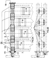
- One of the ends of the valve shaft has a seeger ring and a bolted cover to permit longitudinal expansion only in the direction opposite to the pulleys. (See Fig. 2A).
- a key improvement of the present invention over the above-mentioned prior art lies in its provision of annular grooves and labyrinths formed on an interior wall of the cylindrical jackets to enhance the closing efficiency and heat dissipation of the valve system during operation.
- the present invention includes a series of parallel, circumferential labyrinth grooves etched into the interior wall of the cylindrical jackets between each adjacent cylinder, and a series of parallel, axially extending labyrinth grooves etched into the interior wall of the cylindrical jackets adjacent the lower openings in the jackets.
- an annular fluid seal groove is formed in the interior wall of the jackets in the midst of the circumferential labyrinth grooves.
- the annular fluid seal groove communicates with a supply of pressurized lubricating oil and forms a high pressure fluid seal during engine operation.
- the oil acts as a lubricant and also provides a medium for transferring heat generated during operation of the valve assembly.
- heat transfer lubrication and containment of pressure.
- Additional annular oil groove seals are formed in the interior wall of the jackets adjacent each of the series of labyrinths for providing an additional high pressure fluid seal during engine operation.
- the present invention includes two longitudinal shafts (a) and (b) on the cylinder head 5 aligned with the engine axis, comprising a jacket 1 and a shaft 2 formed with holes, i.e., a holed shaft.
- the engine includes a motor block 7, pistons 8, a cylinder head 5, connecting rod 12, crankshaft 25, a distribution toothed belt 9 (timing belt), distribution and reduction toothed pulley 11, belt tensioner 13, and motion distribution toothed pulley 14.
- a housing for two jackets is provided in the cylinder head cover 5, the cylinder head cover 5 having outer water chambers surrounding the jacket housing for cooling.
- a jacket 1, with perforations or openings 20 from side to side in the vertical plane of the jacket, is inserted into the housing under pressure and with a sealer. Each opening 20 coincides with a combustion chamber of one cylinder of the engine.
- the jacket is preferably of a unitary one-piece construction. This greatly simplifies machining of the assembly and its insertion in the housing.
- a double effect distribution sequential valve shaft 2 is mounted inside the jacket 1 with a very accurate tolerance.
- the shaft also has perforations or openings 22 extending from side to side in the vertical plane.
- Each opening 22 corresponds with an inlet or exhaust port into a respective combustion chamber of the engine.
- the openings 22 are separated from each other along the length of the valve shaft 2 by at least the distance between adjacent cylinders and are placed at a predetermined angle in the vertical plane, depending on the sequence of intake or exhaust and the type of engine.
- the openings 22 extend through the shaft 2 from side to side in the vertical plane, at every complete turn, one of the openings 22 communicates twice through an opening 20 in the jacket 1 with a hole 24 in the head of one combustion chamber of a given cylinder 3, for which reason it is named a "double effect distribution sequential valve.”
- a double effect distribution sequential valve Thus, one complete turn of the crankshaft need only result in 1/4 of a turn of the double effect distribution sequential valve shaft 2.
- the rotation of the valve shaft 2 is transmitted from a pulley 14 on the crankshaft 25 by means of a toothed belt 9 and a pulley 11.
- a corresponding difference of diameters between the pulley 11 and the pulley 14 reduces the number of turns of the valve shaft 2 to 1:4 with respect to the crankshaft.
- the exhaust or intake port in the cylinder head cover 5 is shown at 4 in Fig. 1B, with the lower end of the port in communication with the cylinder 3 shown at 24.
- one of the ends of the valve shaft has a seeger ring 15 and a bolted cover 16 to limit the longitudinal expansion of the valve shaft in the direction opposite to the pulleys.
- the cover 16 which limits the movement of the seeger ring 15 has a double tip rubber lock 17.
- a back locking cover is shown at 18.
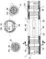
- the present invention includes a series of labyrinths 34 etched into an internal surface of the jacket 1.
- the labyrinths 34 are in the form of a series of circumferential parallel grooves etched into the jacket 1 along a portion of the jacket on each side of the openings 20.
- the labyrinths 34 function to create a barrier of turbulent gas flow which opposes the escape of gases from the combustion chamber during engine operation to enhance the closing efficiency of the valve system. Because the labyrinths are in the form of circumferential parallel grooves, rather than spiral grooves, they have no tendency to impel pressurized fluid.
- a fluid seal groove 32 In the midst of each series of circumferential labyrinths 34 is a fluid seal groove 32 having an oil entry port 35 in fluid communication with the lubricating system of the engine or independent lubrication system.
- the fluid seal groove 32 fills with oil and provides an effective high pressure fluid seal to ensure a very high closing efficiency of the valve system.
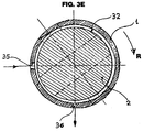
- the oil entry port 35 is accompanied by an oil exit port 36 to allow circulation of lubricating oil through the groove 32 during operation.
- the oil exit port 36 has a smaller diameter than the entry port 35 so that the circulating oil maintains a fluid pressure within the groove 32.
- the entry and exit ports 35 and 36 are circumferentially spaced such that the direction of rotation R of the valve shaft 2 tends to distribute the entering oil about the circumference of the groove before it exits the groove via port 36.
- the oil circulating through the groove 32 enhances the heat transfer away from the valve shaft to help cool the valve system during operation.
- the oil is further cooled on the jacket 1 by water circulating through the water chambers of the cylinder head cover 5.
- Additional fluid seal grooves 33 are formed in the jacket 1 adjacent the openings 20 to provide secondary fluid seals to further enhance the closing efficiency and improve heat transfer.
- the grooves 33 are preferably in fluid communication with the lubrication system so that they maintain fluid pressure about the shaft 2 similar to the grooves 32.
- a series of axially extending labyrinth grooves 34A (Fig. 3C) are etched into the inner surface of the jacket 1 adjacent each side of a lower portion 30 of the openings 20.
- the axially extending labyrinth grooves 34A extend at least the length of the openings 20 and function to create an additional barrier of turbulent gas flow which opposes the escape of gases towards the upper portion of the openings 20.
- the sealing interface between the shaft and the jacket is located at the radially innermost portion of each groove.
- the novel features of the present invention will now be further described with reference to two phases of engine operation.
- the first phase of operation occurs when the engine is first being started and may last for a short time after the engine starts.
- the lubricating system of the engine is either inoperative or has not yet reached its normal operating pressure.
- Fig. 3A it can be seen that the valve shaft is without an oil cushion or bearing supporting it in a sealed fit within the jacket in the first phase of operation (i.e, the minute space 31 between the shaft 2 and jacket 1 is dry). It is to be noted that the close tolerance fit of the valve shaft 2 within the jacket 1 is greatly exaggerated in Fig. 3A for explanatory purposes.
- the fluid seal grooves 32 and 33 do not provide effective fluid seals.
- the closing efficiency of the valve system largely depends on the close tolerance fit between the jacket 1 and shaft 2 and the pressure barriers created by the labyrinths 34 and 34A.
- the labyrinths 34 and 34A create a pressure barrier or brake to substantially reduce the above-mentioned gas escape.
- the braking effect grows exponentially as a square of the speed of the gases.
- the greater the speed of the gases (given by the ratio of compression, the pressure of explosion, and the size of the conduits of escape 31), the greater the resistance to the passage of gas produced by the turbulence, and hence, the barrier created by the labyrinths 34 and 34A.
- the labyrinths 34 and 34A increase the turbulence by opposing an irregular surface transverse to the direction of flow.
- the labyrinths cause a loss of energy of the escaping gases as they expand into one groove after the other.
- the lubrication system of the engine is up to operating pressure so that the fluid seal grooves 32 and 33 are filled with pressurized oil, and the minute space 31 between the shaft 2 and the jacket 1 is effectively filled by a film of oil.
- the lubricating oil enters and exits the annular grooves 32 and 33 under high pressure producing a hydrodynamic barrier to gases seeking to escape in the axial direction along the valve shaft 2 between the cylinders.
- the close tolerance fit of the valve shaft 2 within the jacket 1 is crucial to effective sealing operation of the fluid seals provided by the grooves 32 and 33.
- the circumferential labyrinths 34 may fill up with oil during the second phase of operation to such an extent that they no longer function as labyrinths to dissipate the pressure in escaping gases. However, the distribution of oil throughout the labyrinth grooves 34 further enhances the fluid pressure barrier in the second phase of operation and helps reduce friction and dissipate heat in the system.
- the area of the jack 1 swept by the holes 22 of the valve shaft 2 is largely deprived of lubrication by virtue of the oil-trapping function of the annular grooves 33.
- the oil film is necessarily broken by the successive passage of the holes 22 in front of the openings 20 and 30 in the jacket 1. Therefore, the minute space 31 extending between the annular grooves 33 in front of the openings 20 and 30 in the jacket will not contain oil.
- the shaft 2 maintains its position within the jacket because it is "floating" in an oil bed created along the lubricated sections of the assembly (i.e., between the annular grooves 32 and 33).
- axial labyrinths 34A In the absence of an oil film, pressure containment is provided by the axial labyrinths 34A, which remain operable in both the first and second phases of operation.
- the location of such axial labyrinths, at each side of the lower opening in the jacket, is intended to provide energy dissipation for the gases which would escape from the cylinder in the critical compression and explosion strokes of the engine.
- the labyrinths 34 and 34A provide an effective pressure barrier in the start-up period of the engine when the valve shaft assembly is without oil lubrication.
- the annular grooves 32 and 33 create high pressure fluid seals within the close tolerance fit of the assembly after the engine has run long enough for oil pressure to build up in the cavities 32 and 33.
- lubrication and cooling are enhanced for the valve assembly during operation via oil circulation, oil cooling and water jackets.
- the present invention provides a totally integrated system with superior operating capabilities in all phases of engine operation.
- the shape of the openings in the valve shaft and the projections thereof may be arcs, open or closed and combinations thereof.
- the concentric jacket 1 may be part of the cylinder head cover 5 or a separate replaceable part. Further, all the openings from side to side, corresponding to intake and exhaust, may be on the same shaft.
- the double effect distribution sequential valve shaft may be made of any kind of material adequate to maintain its functioning, such as metal, carbonite, ceramic, KEVLARTM or their alloys or combinations.
- the double effect distribution sequential valve shaft may be located anywhere on or over the cylinder head or to the side of the engine block.
- the rotation of the double effect distribution sequential valve shaft 2 may be transmitted in an indirect way by a chain toothed belt, gearing or any other known transmission system.
Landscapes
- Engineering & Computer Science (AREA)
- Mechanical Engineering (AREA)
- General Engineering & Computer Science (AREA)
- Valve Device For Special Equipments (AREA)
- Multiple-Way Valves (AREA)
- Fluid-Driven Valves (AREA)
- Cylinder Crankcases Of Internal Combustion Engines (AREA)
- Sealing Using Fluids, Sealing Without Contact, And Removal Of Oil (AREA)
Applications Claiming Priority (2)
| Application Number | Priority Date | Filing Date | Title |
|---|---|---|---|
| US08/172,386 US5417188A (en) | 1992-07-20 | 1993-12-23 | Double effect distribution sequential valve shaft assembly |
| US172386 | 1993-12-23 |
Publications (2)
| Publication Number | Publication Date |
|---|---|
| EP0659982A1 true EP0659982A1 (de) | 1995-06-28 |
| EP0659982B1 EP0659982B1 (de) | 1998-04-15 |
Family
ID=22627499
Family Applications (1)
| Application Number | Title | Priority Date | Filing Date |
|---|---|---|---|
| EP94100605A Expired - Lifetime EP0659982B1 (de) | 1993-12-23 | 1994-01-18 | Sequentieller Drehschieber mit doppeltwirkender Steuerung |
Country Status (5)
| Country | Link |
|---|---|
| US (1) | US5417188A (de) |
| EP (1) | EP0659982B1 (de) |
| JP (1) | JPH07208131A (de) |
| AT (1) | ATE165140T1 (de) |
| DE (1) | DE69409619T2 (de) |
Cited By (1)
| Publication number | Priority date | Publication date | Assignee | Title |
|---|---|---|---|---|
| GB2380229A (en) * | 2001-07-05 | 2003-04-02 | Leon Donald Bachelier | Rotary valve |
Families Citing this family (12)
| Publication number | Priority date | Publication date | Assignee | Title |
|---|---|---|---|---|
| EP0673471B1 (de) * | 1992-11-06 | 1998-05-13 | A.E. Bishop Research Pty. Limited | Schmiersystem für drehventil |
| AUPN559395A0 (en) * | 1995-09-22 | 1995-10-19 | Smith, Brian | Rotary valve for an internal combustion engine |
| US5967108A (en) | 1996-09-11 | 1999-10-19 | Kutlucinar; Iskender | Rotary valve system |
| GB9719548D0 (en) | 1997-09-15 | 1997-11-19 | Stone Timothy | Improvements in and relating to internal combustion engines |
| US6095106A (en) * | 1999-07-28 | 2000-08-01 | Kaluris; Emmanuel | Cyclo-valve for internal combustion engines |
| US6311668B1 (en) | 2000-02-14 | 2001-11-06 | Caterpillar Inc. | Monovalve with integrated fuel injector and port control valve, and engine using same |
| JP4596518B2 (ja) * | 2004-06-25 | 2010-12-08 | 株式会社ダンレイ | 湯水混合弁 |
| JP4596517B2 (ja) * | 2004-06-25 | 2010-12-08 | 株式会社ダンレイ | 湯水混合弁 |
| JP2007009777A (ja) * | 2005-06-29 | 2007-01-18 | Soji Nakagawa | 内燃機関の吸気・排気構造 |
| JP5124358B2 (ja) * | 2008-06-18 | 2013-01-23 | 株式会社不二工機 | 流量調整弁 |
| ITTN20100002A1 (it) * | 2010-02-10 | 2011-08-11 | Speccher Renz0 | Dispositivo di distribuzione a "doppio tubo rotante" per motori a scoppio |
| WO2019101981A1 (en) | 2017-11-24 | 2019-05-31 | Brp-Rotax Gmbh & Co. Kg | Exhaust valve assembly for a two-stroke internal combustion engine |
Citations (6)
| Publication number | Priority date | Publication date | Assignee | Title |
|---|---|---|---|---|
| FR441686A (fr) * | 1912-03-23 | 1912-08-13 | Fernand Tribot | Distributeur rotatif pour moteurs à explosions à quatre temps |
| US1413567A (en) * | 1918-10-14 | 1922-04-25 | Bennett William Henry | Internal-combustion engine |
| FR1053298A (fr) * | 1952-04-02 | 1954-02-01 | Distribution rotative pour moteur à combustion | |
| FR2244076A1 (en) * | 1973-09-19 | 1975-04-11 | Kremer Alphonse | IC engine with rotating gas distributor - concentric tubes alternately connect inlet and outlet passages |
| FR2547867A1 (fr) * | 1983-06-24 | 1984-12-28 | Collin Gilbert | Culasse perfectionnee, notamment pour moteurs a explosion, et son application a un compresseur de fluides |
| US4960086A (en) * | 1989-04-10 | 1990-10-02 | Rassey Louis J | Rotary valve construction utilizing a compressed gas as lubricant and coolant |
Family Cites Families (31)
| Publication number | Priority date | Publication date | Assignee | Title |
|---|---|---|---|---|
| FR741463A (de) * | 1900-01-01 | |||
| US924897A (en) * | 1907-11-25 | 1909-06-15 | Gen Electric | Shaft-packing. |
| US1041485A (en) * | 1911-04-29 | 1912-10-15 | Gen Electric | Leakage-reducing device. |
| US2183024A (en) * | 1938-03-30 | 1939-12-12 | William W Large | Rotary valve for engines |
| US2543615A (en) * | 1947-04-24 | 1951-02-27 | Clark Bros Co Inc | Gas seal for rotating shafts |
| US2839036A (en) * | 1956-05-07 | 1958-06-17 | Kiekhaefer Corp | Rotary valve timing mechanism |
| US3871340A (en) * | 1972-10-03 | 1975-03-18 | Tetrahedron Associates Inc | Rotary valve internal combustion engine |
| US3945364A (en) * | 1974-06-24 | 1976-03-23 | Cook Danny G | Rotary valve for internal combustion engine |
| US3993036A (en) * | 1974-08-27 | 1976-11-23 | Tischler Wald E | Internal combustion engine |
| US4163438A (en) * | 1975-11-26 | 1979-08-07 | Dana Corporation | Rotary valve timing apparatus |
| US4019487A (en) * | 1975-11-26 | 1977-04-26 | Dana Corporation | Rotary valve seal assembly |
| US4198946A (en) * | 1977-06-03 | 1980-04-22 | Rassey Louis J | Rotary valve construction for an internal combustion engine |
| FR2428736A1 (fr) * | 1978-06-16 | 1980-01-11 | Honda Motor Co Ltd | Soupape rotative pour moteurs a combustion interne |
| US4333427A (en) * | 1980-08-05 | 1982-06-08 | Antonio Burillo | Internal combustion engine |
| AU7955082A (en) * | 1981-02-25 | 1982-09-02 | Fred L. Baldwin | Rotary valve cylinder head |
| US4545337A (en) * | 1981-12-14 | 1985-10-08 | Lyons George A | Rotary valve engine |
| EP0099873A3 (de) * | 1982-07-19 | 1985-01-09 | Josef V. Illichmann | Zylindrischer Drehschieber mit Abdichtung für Kolbenmotoren |
| US4556023A (en) * | 1983-08-02 | 1985-12-03 | Joseph Giocastro | Rotary valves and gear timing |
| DE3432047C2 (de) * | 1983-09-19 | 1993-11-04 | Suzuki Motor Co | Zweitaktmaschine |
| US4738233A (en) * | 1985-02-25 | 1988-04-19 | Mazda Motor Corporation | Intake system for internal combustion engines |
| WO1986006135A1 (fr) * | 1985-04-10 | 1986-10-23 | Honda Giken Kogyo Kabushiki Kaisha | Structure de connexion dans un mecanisme d'entrainement de soupapes pour des moteurs a combustion interne |
| JPS61237825A (ja) * | 1985-04-12 | 1986-10-23 | Mazda Motor Corp | ロ−タリバルブ付エンジン |
| GB2190139A (en) * | 1986-05-03 | 1987-11-11 | Howard Brian Leitch | Rotary spool valve |
| US4864984A (en) * | 1986-09-02 | 1989-09-12 | Blish Nelson A | Rotary valve internal combustion engine |
| US4832350A (en) * | 1987-12-21 | 1989-05-23 | Orlowski David C | One piece labyrinth seal |
| US4815428A (en) * | 1987-12-31 | 1989-03-28 | Bunk Paul H | Rotary valve internal combustion engine |
| JPH02169818A (ja) * | 1988-12-21 | 1990-06-29 | Fuji Heavy Ind Ltd | 2サイクルエンジン |
| CA1292702C (en) * | 1989-06-23 | 1991-12-03 | George Ristin | Rotary valve with facility for stratified combustion in the internal combustionengine |
| US4976227A (en) * | 1990-04-16 | 1990-12-11 | Draper David J | Internal combustion engine intake and exhaust valve control apparatus |
| US5052349A (en) * | 1990-07-30 | 1991-10-01 | Terry Buelna | Rotary valve for internal combustion engine |
| US5105784A (en) * | 1991-04-08 | 1992-04-21 | General Motors Corporation | Rotary valve and system for duration and phase control |
-
1993
- 1993-12-23 US US08/172,386 patent/US5417188A/en not_active Expired - Fee Related
-
1994
- 1994-01-18 AT AT94100605T patent/ATE165140T1/de not_active IP Right Cessation
- 1994-01-18 EP EP94100605A patent/EP0659982B1/de not_active Expired - Lifetime
- 1994-01-18 DE DE69409619T patent/DE69409619T2/de not_active Expired - Fee Related
- 1994-01-20 JP JP6004815A patent/JPH07208131A/ja active Pending
Patent Citations (6)
| Publication number | Priority date | Publication date | Assignee | Title |
|---|---|---|---|---|
| FR441686A (fr) * | 1912-03-23 | 1912-08-13 | Fernand Tribot | Distributeur rotatif pour moteurs à explosions à quatre temps |
| US1413567A (en) * | 1918-10-14 | 1922-04-25 | Bennett William Henry | Internal-combustion engine |
| FR1053298A (fr) * | 1952-04-02 | 1954-02-01 | Distribution rotative pour moteur à combustion | |
| FR2244076A1 (en) * | 1973-09-19 | 1975-04-11 | Kremer Alphonse | IC engine with rotating gas distributor - concentric tubes alternately connect inlet and outlet passages |
| FR2547867A1 (fr) * | 1983-06-24 | 1984-12-28 | Collin Gilbert | Culasse perfectionnee, notamment pour moteurs a explosion, et son application a un compresseur de fluides |
| US4960086A (en) * | 1989-04-10 | 1990-10-02 | Rassey Louis J | Rotary valve construction utilizing a compressed gas as lubricant and coolant |
Cited By (2)
| Publication number | Priority date | Publication date | Assignee | Title |
|---|---|---|---|---|
| GB2380229A (en) * | 2001-07-05 | 2003-04-02 | Leon Donald Bachelier | Rotary valve |
| GB2380229B (en) * | 2001-07-05 | 2005-06-22 | Leon Donald Bachelier | Rotary valve |
Also Published As
| Publication number | Publication date |
|---|---|
| DE69409619T2 (de) | 1998-09-17 |
| ATE165140T1 (de) | 1998-05-15 |
| JPH07208131A (ja) | 1995-08-08 |
| EP0659982B1 (de) | 1998-04-15 |
| DE69409619D1 (de) | 1998-05-20 |
| US5417188A (en) | 1995-05-23 |
Similar Documents
| Publication | Publication Date | Title |
|---|---|---|
| US5417188A (en) | Double effect distribution sequential valve shaft assembly | |
| US6308677B1 (en) | Overhead rotary valve for engines | |
| US5152259A (en) | Cylinder head for internal combustion engine | |
| KR100490247B1 (ko) | 개선된 축 피스톤 로터리 엔진 | |
| US6257191B1 (en) | Rotary valve system | |
| US5191863A (en) | Rotary sleeve-valve internal combustion engine | |
| US6321699B1 (en) | Spheroidal rotary valve for combustion engines | |
| US5372104A (en) | Rotary valve arrangement | |
| HU219044B (hu) | Axiáldugattyús forgógép | |
| EP0293335B1 (de) | Steuerungsvorrichtung für Hubkolbenmaschinen, wie endothermische Hubmaschinen, mit einem Drehventil in Form eines Drehkörpers, insbesondere einer Kugel | |
| GB2284860A (en) | Liquid cooled i.c.engine cylinder head | |
| JPH0230911A (ja) | ロータリーバルブ式内燃機関 | |
| EP0801211B1 (de) | Vorrichtung zum Verändern der Steuerzeiten einer Brennkraftmaschine | |
| US20020104497A1 (en) | Accessory drive for the valves of an internal combustion engine | |
| KR20100080558A (ko) | 내연 기관용 로터리 밸브 시일 | |
| US5072705A (en) | Rotary engine and method | |
| US4867117A (en) | Rotary valve with integrated combustion chamber | |
| EP0579903A1 (de) | Sequentieller Drehschieber mit doppelt wirkender Steuerung | |
| US5350287A (en) | Rotary engine and cam-operated working member assembly | |
| KR100872640B1 (ko) | 캠 샤프트 마찰 저감을 위한 오일 공급 통로 | |
| WO1996032569A1 (en) | Rotary valve for internal combustion engine | |
| US4313401A (en) | Regulator for an internal combustion engine | |
| US5230307A (en) | Internal combustion engine having rotary engine body | |
| US5133305A (en) | Internal combustion engine having rotary engine body | |
| WO2022061444A1 (en) | Internal combustion engine |
Legal Events
| Date | Code | Title | Description |
|---|---|---|---|
| PUAI | Public reference made under article 153(3) epc to a published international application that has entered the european phase |
Free format text: ORIGINAL CODE: 0009012 |
|
| AK | Designated contracting states |
Kind code of ref document: A1 Designated state(s): AT DE ES FR GB IT SE |
|
| 17P | Request for examination filed |
Effective date: 19950906 |
|
| 17Q | First examination report despatched |
Effective date: 19960118 |
|
| GRAG | Despatch of communication of intention to grant |
Free format text: ORIGINAL CODE: EPIDOS AGRA |
|
| GRAG | Despatch of communication of intention to grant |
Free format text: ORIGINAL CODE: EPIDOS AGRA |
|
| GRAH | Despatch of communication of intention to grant a patent |
Free format text: ORIGINAL CODE: EPIDOS IGRA |
|
| GRAH | Despatch of communication of intention to grant a patent |
Free format text: ORIGINAL CODE: EPIDOS IGRA |
|
| GRAA | (expected) grant |
Free format text: ORIGINAL CODE: 0009210 |
|
| AK | Designated contracting states |
Kind code of ref document: B1 Designated state(s): AT DE ES FR GB IT SE |
|
| PG25 | Lapsed in a contracting state [announced via postgrant information from national office to epo] |
Ref country code: IT Free format text: LAPSE BECAUSE OF FAILURE TO SUBMIT A TRANSLATION OF THE DESCRIPTION OR TO PAY THE FEE WITHIN THE PRESCRIBED TIME-LIMIT;WARNING: LAPSES OF ITALIAN PATENTS WITH EFFECTIVE DATE BEFORE 2007 MAY HAVE OCCURRED AT ANY TIME BEFORE 2007. THE CORRECT EFFECTIVE DATE MAY BE DIFFERENT FROM THE ONE RECORDED. Effective date: 19980415 Ref country code: FR Free format text: LAPSE BECAUSE OF FAILURE TO SUBMIT A TRANSLATION OF THE DESCRIPTION OR TO PAY THE FEE WITHIN THE PRESCRIBED TIME-LIMIT Effective date: 19980415 Ref country code: ES Free format text: THE PATENT HAS BEEN ANNULLED BY A DECISION OF A NATIONAL AUTHORITY Effective date: 19980415 Ref country code: AT Free format text: LAPSE BECAUSE OF FAILURE TO SUBMIT A TRANSLATION OF THE DESCRIPTION OR TO PAY THE FEE WITHIN THE PRESCRIBED TIME-LIMIT Effective date: 19980415 |
|
| REF | Corresponds to: |
Ref document number: 165140 Country of ref document: AT Date of ref document: 19980515 Kind code of ref document: T |
|
| REF | Corresponds to: |
Ref document number: 69409619 Country of ref document: DE Date of ref document: 19980520 |
|
| PG25 | Lapsed in a contracting state [announced via postgrant information from national office to epo] |
Ref country code: SE Free format text: LAPSE BECAUSE OF FAILURE TO SUBMIT A TRANSLATION OF THE DESCRIPTION OR TO PAY THE FEE WITHIN THE PRESCRIBED TIME-LIMIT Effective date: 19980715 |
|
| EN | Fr: translation not filed | ||
| PG25 | Lapsed in a contracting state [announced via postgrant information from national office to epo] |
Ref country code: GB Free format text: LAPSE BECAUSE OF NON-PAYMENT OF DUE FEES Effective date: 19990118 |
|
| PLBE | No opposition filed within time limit |
Free format text: ORIGINAL CODE: 0009261 |
|
| STAA | Information on the status of an ep patent application or granted ep patent |
Free format text: STATUS: NO OPPOSITION FILED WITHIN TIME LIMIT |
|
| 26N | No opposition filed | ||
| GBPC | Gb: european patent ceased through non-payment of renewal fee |
Effective date: 19990118 |
|
| PG25 | Lapsed in a contracting state [announced via postgrant information from national office to epo] |
Ref country code: DE Free format text: LAPSE BECAUSE OF NON-PAYMENT OF DUE FEES Effective date: 19991103 |