EP0660355A1 - Structure de maintien du noyau de fer d'un contacteur électromagnétique - Google Patents
Structure de maintien du noyau de fer d'un contacteur électromagnétique Download PDFInfo
- Publication number
- EP0660355A1 EP0660355A1 EP94120199A EP94120199A EP0660355A1 EP 0660355 A1 EP0660355 A1 EP 0660355A1 EP 94120199 A EP94120199 A EP 94120199A EP 94120199 A EP94120199 A EP 94120199A EP 0660355 A1 EP0660355 A1 EP 0660355A1
- Authority
- EP
- European Patent Office
- Prior art keywords
- iron core
- receiving surfaces
- lower casing
- leaf spring
- retaining structure
- Prior art date
- Legal status (The legal status is an assumption and is not a legal conclusion. Google has not performed a legal analysis and makes no representation as to the accuracy of the status listed.)
- Granted
Links
Images


Classifications
-
- H—ELECTRICITY
- H01—ELECTRIC ELEMENTS
- H01H—ELECTRIC SWITCHES; RELAYS; SELECTORS; EMERGENCY PROTECTIVE DEVICES
- H01H50/00—Details of electromagnetic relays
- H01H50/16—Magnetic circuit arrangements
-
- H—ELECTRICITY
- H01—ELECTRIC ELEMENTS
- H01H—ELECTRIC SWITCHES; RELAYS; SELECTORS; EMERGENCY PROTECTIVE DEVICES
- H01H50/00—Details of electromagnetic relays
- H01H50/16—Magnetic circuit arrangements
- H01H50/18—Movable parts of magnetic circuits, e.g. armature
- H01H50/30—Mechanical arrangements for preventing or damping vibration or shock, e.g. by balancing of armature
- H01H50/305—Mechanical arrangements for preventing or damping vibration or shock, e.g. by balancing of armature damping vibration due to functional movement of armature
Definitions
- the present invention relates to an iron core retaining structure of an electromagnetic contactor which switches on and off an electric source for an electrical equipment such as a motor.
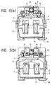
- FIG. 5 shows an example of a conventional electromagnetic contactor of this type.
- Fig. 5(a) is a sectional view of the electromagnetic contactor
- Fig. 5(b) is a sectional view of the same electromagnetic contactor in its making state, for explaining the operation of the electromagnetic contactor.
- a central leg of an E-shaped fixed iron core 3 is inserted into an exciting coil 5.
- a movable iron core 4 placed so as to be opposite to the fixed iron core 3 is connected to a movable contact support 6 through a connection plate 7 and supported by a return spring 8.
- the movable iron core 4 and the fixed iron core 3 are placed in a lower casing 2, with an upper portion of the movable iron core 4 left outside.
- the back portion of the fixed iron core 3 is mounted on a bottom plate of the lower casing 2 through an elastic sheet 13 such as a rubber material.
- An upper casing 1 defines, by its lower surface 1a, the upward moving distance of the movable contact support 6.
- a fixed contact 9 attached on the upper surface of the upper casing 1 is made to be opposite to a movable contact 10.
- the movable contact 10 is attached on the movable contact support 6 so as to be pressed by means of a contact spring 12.
- Electromagnetic contactor mounting portions 2a are provided on the lower casing 2.
- the elastic sheet 13 is provided so that the fixed iron core 3 is pressed against the elastic sheet 13 and the elastic sheet 13 absorbs the impact force acting on the fixed iron core 3 because of its flexibility.
- the impact force acting on the movable iron core 4 is also absorbed when the impact force acting on the fixed iron core 3 is absorbed, whereby the contacts are prevented from chattering.
- an elastic sheet such as a rubber material is disposed between the back portion of the fixed iron core and the bottom plate of the lower casing in order to absorb impact force due to the collision of the movable iron core against the fixed iron core.
- the quantity of flexion of the electric sheet is however small, so that the effect of absorption of the impact force is not always sufficient.
- the impact force acts on the bottom plate of the lower casing on which the electromagnetic contactor mounting portions are provided. Therefore, when the electromagnetic contactor is mounted on a panel, the impact given to the panel and noises are large, so that the adverse affect may be caused on other devices mounted on the panel.
- An object of the present invention is to provide an iron core retaining structure of an electromagnetic contactor for reducing impact force due to the collision of a movable iron core against a fixed iron core at the time of making operation of the electromagnetic contactor, and for particularly reducing impact force acting on a bottom plate of a lower casing on which portions for mounting the electromagnetic contactor are provided, and for making it easy to assemble the electromagnetic contactor.
- an iron core retaining structure of an electromagnetic contactor for retaining a back portion of a fixed iron core onto a bottom plate of a lower casing, the fixed iron core having a leg which is inserted into an exciting coil, wherein a convex leaf spring having opposite end portions bent at right angles to form lower pressure-receiving surfaces and side pressure-receiving surfaces respectively is disposed between the fixed iron core and the bottom plate of the lower casing so that the lower pressure-receiving surfaces and the side pressure-receiving surfaces are brought into contact with the bottom plate of the lower casing and with side walls of the lower casing, respectively.
- buffer materials each having a larger side surface than each of the side pressure-receiving surfaces of the leaf spring are disposed between the side pressure-receiving surfaces formed at opposite end portions of the leaf spring and the side walls of the lower casing.
- recesses or blind-holes are provided in inner surfaces of the buffer materials so that the bent portions including the lower pressure-receiving surfaces and the side pressure-receiving surfaces formed at the opposite end portions of the leaf spring are closely inserted into the buffer materials, respectively.
- beam portions capable of being bent at right angles are formed respectively in the side walls of the lower casing with which the side pressure-receiving surfaces formed at the opposite end portions of the leaf spring are in contact.
- a convex leaf spring having opposite end portions bent at right angles to form lower pressure-receiving surfaces and side pressure-receiving surfaces respectively is disposed between the fixed iron core and the bottom plate of the lower casing so that the lower pressure-receiving surfaces and the side pressure-receiving surfaces are brought into contact with the bottom plate of the lower casing and with side walls of the lower casing, respectively.
- the leaf spring bends greatly to thereby absorb the impact force acting on the fixed iron core, and, at the same time, diffuse the impact force to the bottom plate of the lower casing through the lower pressure-receiving surfaces and to the side walls of the lower casing through the side pressure-receiving surfaces. Accordingly, impact force due to the collision of the movable iron core against the fixed iron core, particularly, impact force acting on the bottom plate of the lower casing in which the electromagnetic contactor mounting portions are provided, is reduced.
- buffer materials each having a larger side surface than each of the side pressure-receiving surfaces of the leaf spring may be disposed between the side pressure-receiving surfaces formed at opposite end portions of the leaf spring and the side walls of the lower casing. Accordingly, when the movable iron core collides against the fixed iron core, impact force from the side pressure-receiving surfaces is diffused to the side walls of the lower casing by the buffer materials. Consequently, even side walls having small withstanding pressure can be used safely.
- recesses may be provided in inner surfaces of the buffer materials so that the bent portions including the lower pressure-receiving surfaces and the side pressure-receiving surfaces formed at the opposite end portions of the leaf spring are closely inserted into the buffer materials, respectively. Accordingly, the leaf spring and the buffer materials formed at the opposite end portions of the leaf spring are connected to each other so as to be united into one body, so that assembling of the leaf spring and the two buffer materials into the lower casing is made easy.
- beam portions capable of being bent in the direction perpendicular to the side walls of the lower casing are further formed respectively in the side walls of the lower casing with which the side pressure-receiving surfaces formed at the opposite end portions of the leaf spring are in contact. Accordingly, when the movable iron core collides against the fixed iron core, impact force from the side pressure-receiving surfaces is absorbed by the bending or flexion of the beam portions. Consequently, even side walls having small withstanding pressure may be used safely.
- Fig. 1(a) is a sectional view of an iron core retaining structure of an electromagnetic contactor according to an embodiment of the present invention
- Fig. 1(b) is a perspective view of a leaf spring depicted in Fig. 1(a).
- Fig. 2(a) is a sectional view of an iron core retaining structure of an electromagnetic contactor according to another embodiment of the present invention
- Fig. 2(b) is a perspective view of a leaf spring and opposite side members depicted in Fig. 2(a).
- Fig. 3(a) is a sectional view of an iron core retaining structure of an electromagnetic contactor according to a further embodiment of the present invention
- Fig. 3(b) is a perspective view of a leaf spring and opposite side members depicted in Fig. 3(b).
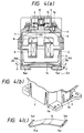
- Fig. 4(a) is a sectional view of an iron core retaining structure of an electromagnetic contactor according to a yet further embodiment of the present invention
- Fig. 4(b) is a perspective view of important part of the structure depicted in Fig. 4(a)
- Fig. 4(c) is a perspective view of a leaf spring depicted in Fig. 4(a).
- Fig. 5(a) is a sectional view of an example of a conventional iron core retaining structure of an electromagnetic contactor
- Fig. 5(b) is a sectional view of the structure in a making state for explaining the operation of the electromagnetic contactor.
- Figs. 1(a) and 1(b) show an embodiment of an iron core retaining structure of an electromagnetic contactor according to the present invention, wherein Fig. 1(a) is a sectional view of the structure and Fig. 1(b) is a perspective view of a leaf spring 14 depicted in Fig. 1(a).
- Fig. 1(a) is a sectional view of the structure
- Fig. 1(b) is a perspective view of a leaf spring 14 depicted in Fig. 1(a).
- a point of difference between the embodiment shown in Fig. 1(a) and the conventional case shown in Fig. 5(a) is in that the elastic sheet 13 of Fig. 5(a) is replaced by a convex leaf spring 14 in Fig. 1(a).
- the opposite end portions of the convex leaf spring 14 are bent upward substantially at right angles so as to form lower pressure-receiving surfaces 14a and side pressure-receiving surfaces 14b.
- the side pressure-receiving surfaces 14b are in slight contact with side walls, respectively, of a lower casing 2.
- an exciting coil 5 When an exciting coil 5 is energized with an electric current, that is, when a movable iron core 4 moves to and collides against a fixed iron core 3, the fixed iron core 3 is pressed against the convex portion of the leaf spring 14 by impact force due to the collision. At this time, the leaf spring 14 bends greatly to thereby absorb the impact force acting on the fixed iron core 3 and, at the same time, diffuse the impact force to a bottom plate of the lower casing 2 through the lower pressure-receiving surfaces 14a and to the side walls of the lower casing 2 through the side pressure-receiving surfaces 14b.
- the leaf spring 14 bends greatly to thereby absorb the impact force acting on the fixed iron core 3 and diffuse the impact force to the bottom plate and side walls of the lower casing 2, the impact force acting on the bottom plate of the lower casing 2 on which electromagnetic contactor mounting portions 2a are provided is reduced remarkably. Accordingly, when the electromagnetic contactor is mounted onto a panel, not only the impact against the panel but also noises generated are reduced.
- Figs. 2(a) and 2(b) show another embodiment of the iron core retaining structure according to the present invention, wherein Fig. 2(a) is a sectional view of the structure, and Fig. 2(b) is a perspective view of a leaf spring 14 and side members 15 depicted in Fig. 2(a).
- a point of difference between the embodiment shown in Fig. 2(a) and the embodiment shown in Fig. 1(a) is in that buffer materials 15 each having a larger side surface in area than each side pressure-receiving surface 14b of the leaf spring 14 are provided respectively between the side pressure-receiving surfaces 14b of the leaf spring 14 and the side walls of the lower casing 2 in Fig. 2.
- Figs. 3(a) and 3(b) show a further embodiment of the iron core retaining structure according to the present invention, wherein Fig. 3(a) is a sectional view of the structure, and Fig. 3(b) is a perspective view of a leaf spring 14 and buffer materials 16 depicted in Fig. 3(a).
- a point of difference between the embodiment shown in Fig. 3(a) and the embodiment shown in Fig. 2(a) is in that the buffer materials 15 in Fig. 2(a) are replaced by buffer materials 16 in Fig. 3(a).
- the buffer materials 16 are provided with recesses or blind-holes 16a, respectively, which are formed in the inner surfaces of buffer materials like the buffer materials 15 in Fig. 2(a) so that bent portions where the lower pressure-receiving surfaces 14a and the side pressure-receiving surfaces 14b are formed at the opposite end portions of the leaf spring 14 are closely inserted into the recesses 16a, respectively.
- the embodiment in Fig. 2(a) is generally assembled such that the respective buffer materials 15 are disposed at the opposite side ends of the bottom plate of the lower casing 2 before the leaf spring 14 is inserted into the lower casing 2 from the upper portion
- the embodiment in Fig. 3(a) is generally assembled such that bent portions where the lower pressure-receiving surfaces 14a and the side pressure-receiving surfaces 14b are formed at the opposite end portions of the leaf spring 14 are closely inserted into the recesses 16a, respectively, of the buffer materials 16 to form the leaf spring 14 and the buffer as one unit, and then the unit of the leaf spring 14 and the buffer materials 16 is inserted into the lower casing 2 from the upper portion.
- the embodiment in Fig. 3(a) has an advantage in that easy assembling such as automatic assembling can be made.
- Figs. 4(a), 4(b) and 4(c) show a further embodiment of the iron core retaining structure according to the present invention, wherein Fig. 4(a) is a sectional view of the structure, Fig. 4(b) is a perspective view of important part of the structure depicted in Fig. 4(a), and Fig. 4(c) is a perspective view of a leaf spring 14 depicted in Fig. 4(a).
- a point of difference between the embodiment shown in Fig. 4(a) and the embodiment shown in Fig. 1(a) is in that U-shaped slits are formed in the side walls, respectively, of the lower casing in Fig.
- the iron core retaining structure of an electromagnetic contactor In the iron core retaining structure of an electromagnetic contactor according to the present invention, impact force due to the collision of the movable iron core against the fixed iron core in the electromagnetic contactor, especially, impact force against the bottom plate of the lower casing where the electromagnetic contactor mounting portions are provided, is reduced. Accordingly, when the electromagnetic contactor is mounted onto a panel, both the impact force and noises given to the panel are reduced so that other devices mounted on the same panel are free from the adverse effect of the impact force. In addition, assembling of the iron core retaining structure may be carried out easily similarly to the assembling in the conventional structure.
Landscapes
- Physics & Mathematics (AREA)
- Electromagnetism (AREA)
- Electromagnets (AREA)
- Building Environments (AREA)
- Switch Cases, Indication, And Locking (AREA)
- Vibration Prevention Devices (AREA)
Applications Claiming Priority (2)
| Application Number | Priority Date | Filing Date | Title |
|---|---|---|---|
| JP322961/93 | 1993-12-22 | ||
| JP5322961A JPH07182961A (ja) | 1993-12-22 | 1993-12-22 | 電磁接触器の鉄心保持構造 |
Publications (2)
| Publication Number | Publication Date |
|---|---|
| EP0660355A1 true EP0660355A1 (fr) | 1995-06-28 |
| EP0660355B1 EP0660355B1 (fr) | 1997-11-12 |
Family
ID=18149581
Family Applications (1)
| Application Number | Title | Priority Date | Filing Date |
|---|---|---|---|
| EP94120199A Expired - Lifetime EP0660355B1 (fr) | 1993-12-22 | 1994-12-20 | Structure de maintien du noyau de fer d'un contacteur électromagnétique |
Country Status (7)
| Country | Link |
|---|---|
| US (1) | US5495220A (fr) |
| EP (1) | EP0660355B1 (fr) |
| JP (1) | JPH07182961A (fr) |
| KR (1) | KR0151742B1 (fr) |
| CN (1) | CN1040262C (fr) |
| DE (1) | DE69406767T2 (fr) |
| TW (1) | TW414905B (fr) |
Cited By (8)
| Publication number | Priority date | Publication date | Assignee | Title |
|---|---|---|---|---|
| WO1997014166A3 (fr) * | 1995-10-12 | 1997-10-30 | Siemens Ag | Boitier pour appareils de commutation |
| WO1997014165A3 (fr) * | 1995-10-12 | 1997-10-30 | Siemens Ag | Dispositif d'amortissement magnetique |
| FR2805390A1 (fr) * | 2000-02-17 | 2001-08-24 | Chint Group Corp | Contacteur a courant alternatif |
| WO2002063646A3 (fr) * | 2000-12-14 | 2002-11-21 | Think Outside Inc | Interrupteur a cle |
| EP1548781A3 (fr) * | 2003-12-22 | 2008-02-13 | Omron Corporation | Relais électromagnétique |
| WO2011009694A1 (fr) * | 2009-07-22 | 2011-01-27 | Siemens Aktiengesellschaft | Appareil de commutation à dispositif d'amortissement |
| EP2924701A1 (fr) * | 2014-03-27 | 2015-09-30 | Siemens Aktiengesellschaft | Bloc de rehausse d'un appareil de commutation basse tension |
| CN119361378A (zh) * | 2024-12-25 | 2025-01-24 | 内蒙古凯仕达机电工程有限公司 | 充电开关控制组件及免平台对接防占位、篡位充电的系统 |
Families Citing this family (18)
| Publication number | Priority date | Publication date | Assignee | Title |
|---|---|---|---|---|
| RU2138091C1 (ru) * | 1998-02-24 | 1999-09-20 | Виктор Александрович Рягузов | Электромагнит |
| RU2339113C2 (ru) * | 2006-10-18 | 2008-11-20 | Открытое акционерное общество "Всероссийский научно-исследовательский проектно-конструкторский и технологический институт релестроения с опытным производством" | Электромагнитный коммутационный аппарат (варианты) |
| RU2433500C2 (ru) * | 2009-04-09 | 2011-11-10 | Иван Захарович Ахазов | Электромагнитный коммутационный аппарат с управлением на постоянном токе |
| JP5277078B2 (ja) * | 2009-06-04 | 2013-08-28 | 株式会社日立産機システム | 電磁接触器 |
| DE102009034611B4 (de) * | 2009-07-27 | 2019-10-02 | Siemens Aktiengesellschaft | Schaltgerät mit Dämpfungsanordnung |
| JP5809443B2 (ja) * | 2011-05-19 | 2015-11-10 | 富士電機株式会社 | 接点機構及びこれを使用した電磁接触器 |
| JP5776449B2 (ja) * | 2011-08-30 | 2015-09-09 | 株式会社デンソー | 電磁スイッチ |
| JP5793048B2 (ja) * | 2011-10-07 | 2015-10-14 | 富士電機株式会社 | 電磁接触器 |
| JP5856426B2 (ja) * | 2011-10-07 | 2016-02-09 | 富士電機株式会社 | 接点装置及びこれを使用した電磁接触器 |
| CN104584173B (zh) * | 2012-11-05 | 2017-03-08 | 三菱电机株式会社 | 电磁接触器 |
| AT515040B1 (de) * | 2013-10-25 | 2017-12-15 | Blum Gmbh Julius | Antriebsvorrichtung für ein bewegbares Möbelteil |
| CN103646824B (zh) * | 2013-11-30 | 2015-12-16 | 德力西电气有限公司 | 接触器电磁系统 |
| CN105934809B (zh) * | 2014-05-20 | 2018-04-27 | 富士电机机器制御株式会社 | 电磁接触器 |
| TWI575544B (zh) * | 2015-06-30 | 2017-03-21 | Solen Electric Co Ltd | Solenoid |
| CN105118741A (zh) * | 2015-09-28 | 2015-12-02 | 林勇 | 节能接触器结构系统 |
| JP6867343B2 (ja) * | 2018-09-03 | 2021-04-28 | Ckd株式会社 | 電磁弁 |
| CN109119290B (zh) * | 2018-09-17 | 2023-11-17 | 浙江天正电气股份有限公司 | 接触器 |
| WO2020184108A1 (fr) * | 2019-03-12 | 2020-09-17 | アルプスアルパイン株式会社 | Dispositif d'entraînement magnétique et dispositif de fonctionnement |
Citations (6)
| Publication number | Priority date | Publication date | Assignee | Title |
|---|---|---|---|---|
| FR1374384A (fr) * | 1962-07-02 | 1964-10-09 | Square D Co | Relais électromagnétique |
| US3196231A (en) * | 1960-02-12 | 1965-07-20 | Licentia Gmbh | Switch which reduces rebounding of its contacts |
| US3467921A (en) * | 1968-03-04 | 1969-09-16 | Furnas Electric Co | Magnetic contactor with special supporting frame |
| DE7107335U (fr) * | 1970-04-13 | 1971-07-15 | Ghisalba Spa | |
| DE2411539A1 (de) * | 1974-03-11 | 1975-09-25 | Siemens Ag | Anordnung zur halterung des nichtschaltenden magnetteils |
| DD213787A1 (de) * | 1983-02-11 | 1984-09-19 | Oppach Schaltelektronik | Daempfungsanordnung fuer elektromagnetisch betaetigte schaltgeraete |
Family Cites Families (2)
| Publication number | Priority date | Publication date | Assignee | Title |
|---|---|---|---|---|
| DE213787C (fr) * | ||||
| DE1776914U (de) * | 1958-02-17 | 1958-11-06 | Licentia Gmbh | Befestigung des magnetankers am beweglichen schaltteil von elektromagneten, insbesondere bei schuetzen. |
-
1993
- 1993-12-22 JP JP5322961A patent/JPH07182961A/ja active Pending
-
1994
- 1994-11-05 TW TW083110236A patent/TW414905B/zh not_active IP Right Cessation
- 1994-12-20 DE DE69406767T patent/DE69406767T2/de not_active Expired - Lifetime
- 1994-12-20 EP EP94120199A patent/EP0660355B1/fr not_active Expired - Lifetime
- 1994-12-21 US US08/360,885 patent/US5495220A/en not_active Expired - Fee Related
- 1994-12-22 CN CN94120016A patent/CN1040262C/zh not_active Expired - Fee Related
- 1994-12-22 KR KR1019940035933A patent/KR0151742B1/ko not_active Expired - Fee Related
Patent Citations (6)
| Publication number | Priority date | Publication date | Assignee | Title |
|---|---|---|---|---|
| US3196231A (en) * | 1960-02-12 | 1965-07-20 | Licentia Gmbh | Switch which reduces rebounding of its contacts |
| FR1374384A (fr) * | 1962-07-02 | 1964-10-09 | Square D Co | Relais électromagnétique |
| US3467921A (en) * | 1968-03-04 | 1969-09-16 | Furnas Electric Co | Magnetic contactor with special supporting frame |
| DE7107335U (fr) * | 1970-04-13 | 1971-07-15 | Ghisalba Spa | |
| DE2411539A1 (de) * | 1974-03-11 | 1975-09-25 | Siemens Ag | Anordnung zur halterung des nichtschaltenden magnetteils |
| DD213787A1 (de) * | 1983-02-11 | 1984-09-19 | Oppach Schaltelektronik | Daempfungsanordnung fuer elektromagnetisch betaetigte schaltgeraete |
Cited By (12)
| Publication number | Priority date | Publication date | Assignee | Title |
|---|---|---|---|---|
| WO1997014166A3 (fr) * | 1995-10-12 | 1997-10-30 | Siemens Ag | Boitier pour appareils de commutation |
| WO1997014165A3 (fr) * | 1995-10-12 | 1997-10-30 | Siemens Ag | Dispositif d'amortissement magnetique |
| US6037852A (en) * | 1995-10-12 | 2000-03-14 | Siemens Ag | Magnet damping arrangement |
| US6583695B1 (en) | 1995-10-12 | 2003-06-24 | Siemens Aktiengesellschaft | Housing for switchgears |
| FR2805390A1 (fr) * | 2000-02-17 | 2001-08-24 | Chint Group Corp | Contacteur a courant alternatif |
| WO2002063646A3 (fr) * | 2000-12-14 | 2002-11-21 | Think Outside Inc | Interrupteur a cle |
| EP1548781A3 (fr) * | 2003-12-22 | 2008-02-13 | Omron Corporation | Relais électromagnétique |
| WO2011009694A1 (fr) * | 2009-07-22 | 2011-01-27 | Siemens Aktiengesellschaft | Appareil de commutation à dispositif d'amortissement |
| CN102473553A (zh) * | 2009-07-22 | 2012-05-23 | 西门子公司 | 带有减震结构的开关装置 |
| CN102473553B (zh) * | 2009-07-22 | 2016-02-03 | 西门子公司 | 带有减震结构的开关装置 |
| EP2924701A1 (fr) * | 2014-03-27 | 2015-09-30 | Siemens Aktiengesellschaft | Bloc de rehausse d'un appareil de commutation basse tension |
| CN119361378A (zh) * | 2024-12-25 | 2025-01-24 | 内蒙古凯仕达机电工程有限公司 | 充电开关控制组件及免平台对接防占位、篡位充电的系统 |
Also Published As
| Publication number | Publication date |
|---|---|
| JPH07182961A (ja) | 1995-07-21 |
| KR950020835A (ko) | 1995-07-24 |
| EP0660355B1 (fr) | 1997-11-12 |
| CN1040262C (zh) | 1998-10-14 |
| DE69406767T2 (de) | 1998-03-12 |
| KR0151742B1 (ko) | 1998-10-15 |
| TW414905B (en) | 2000-12-11 |
| CN1111804A (zh) | 1995-11-15 |
| DE69406767D1 (de) | 1997-12-18 |
| US5495220A (en) | 1996-02-27 |
Similar Documents
| Publication | Publication Date | Title |
|---|---|---|
| EP0660355B1 (fr) | Structure de maintien du noyau de fer d'un contacteur électromagnétique | |
| US5160910A (en) | Electromagnetic relay | |
| EP3264437A2 (fr) | Relais électromagnétique | |
| EP0049088A2 (fr) | Relais électromagnétique | |
| JPH11213839A (ja) | 電磁継電器 | |
| US5597332A (en) | Solder contact | |
| US5577601A (en) | Actuating device for a monitor power switch | |
| JP2518853B2 (ja) | 電磁式の継電器 | |
| JP4071493B2 (ja) | 押しボタン装置 | |
| US5070315A (en) | Electromagnetic relay | |
| US4340876A (en) | Magnetic armature mounting in particular for minicompact relays | |
| JP2020047464A (ja) | 電気機器の接続構造 | |
| JP3031149B2 (ja) | 封止接点装置 | |
| KR100451918B1 (ko) | 전기콘택터스프링 | |
| EP0024922A1 (fr) | Interrupteurs à action brusque | |
| GB2175451A (en) | Pushbutton switch | |
| JPS6114136Y2 (fr) | ||
| JPS6350747Y2 (fr) | ||
| JPS645732B2 (fr) | ||
| JP2993573B2 (ja) | 棒移動支持機構 | |
| JPS61218037A (ja) | リレー | |
| JP3255672B2 (ja) | 電磁継電器 | |
| JPH0537383Y2 (fr) | ||
| KR890000051Y1 (ko) | 자동 복귀형 스위치 | |
| JPH0754909Y2 (ja) | 電磁継電器 |
Legal Events
| Date | Code | Title | Description |
|---|---|---|---|
| PUAI | Public reference made under article 153(3) epc to a published international application that has entered the european phase |
Free format text: ORIGINAL CODE: 0009012 |
|
| AK | Designated contracting states |
Kind code of ref document: A1 Designated state(s): DE FR GB |
|
| 17P | Request for examination filed |
Effective date: 19951004 |
|
| GRAG | Despatch of communication of intention to grant |
Free format text: ORIGINAL CODE: EPIDOS AGRA |
|
| 17Q | First examination report despatched |
Effective date: 19970117 |
|
| GRAH | Despatch of communication of intention to grant a patent |
Free format text: ORIGINAL CODE: EPIDOS IGRA |
|
| GRAH | Despatch of communication of intention to grant a patent |
Free format text: ORIGINAL CODE: EPIDOS IGRA |
|
| GRAA | (expected) grant |
Free format text: ORIGINAL CODE: 0009210 |
|
| AK | Designated contracting states |
Kind code of ref document: B1 Designated state(s): DE FR GB |
|
| REF | Corresponds to: |
Ref document number: 69406767 Country of ref document: DE Date of ref document: 19971218 |
|
| ET | Fr: translation filed | ||
| PLBE | No opposition filed within time limit |
Free format text: ORIGINAL CODE: 0009261 |
|
| STAA | Information on the status of an ep patent application or granted ep patent |
Free format text: STATUS: NO OPPOSITION FILED WITHIN TIME LIMIT |
|
| 26N | No opposition filed | ||
| REG | Reference to a national code |
Ref country code: GB Ref legal event code: IF02 |
|
| PGFP | Annual fee paid to national office [announced via postgrant information from national office to epo] |
Ref country code: GB Payment date: 20021218 Year of fee payment: 9 |
|
| REG | Reference to a national code |
Ref country code: FR Ref legal event code: D6 |
|
| PG25 | Lapsed in a contracting state [announced via postgrant information from national office to epo] |
Ref country code: GB Free format text: LAPSE BECAUSE OF NON-PAYMENT OF DUE FEES Effective date: 20031220 |
|
| GBPC | Gb: european patent ceased through non-payment of renewal fee |
Effective date: 20031220 |
|
| REG | Reference to a national code |
Ref country code: FR Ref legal event code: TP |
|
| REG | Reference to a national code |
Ref country code: FR Ref legal event code: TP |
|
| PGFP | Annual fee paid to national office [announced via postgrant information from national office to epo] |
Ref country code: FR Payment date: 20091221 Year of fee payment: 16 |
|
| PGFP | Annual fee paid to national office [announced via postgrant information from national office to epo] |
Ref country code: DE Payment date: 20091217 Year of fee payment: 16 |
|
| REG | Reference to a national code |
Ref country code: FR Ref legal event code: ST Effective date: 20110831 |
|
| PG25 | Lapsed in a contracting state [announced via postgrant information from national office to epo] |
Ref country code: FR Free format text: LAPSE BECAUSE OF NON-PAYMENT OF DUE FEES Effective date: 20110103 |
|
| PG25 | Lapsed in a contracting state [announced via postgrant information from national office to epo] |
Ref country code: DE Free format text: LAPSE BECAUSE OF NON-PAYMENT OF DUE FEES Effective date: 20110701 |
|
| REG | Reference to a national code |
Ref country code: DE Ref legal event code: R119 Ref document number: 69406767 Country of ref document: DE Effective date: 20110701 |