EP0660462A1 - Douille de lampe à incandescence et projecteur équipé d'une telle douille - Google Patents
Douille de lampe à incandescence et projecteur équipé d'une telle douille Download PDFInfo
- Publication number
- EP0660462A1 EP0660462A1 EP94118546A EP94118546A EP0660462A1 EP 0660462 A1 EP0660462 A1 EP 0660462A1 EP 94118546 A EP94118546 A EP 94118546A EP 94118546 A EP94118546 A EP 94118546A EP 0660462 A1 EP0660462 A1 EP 0660462A1
- Authority
- EP
- European Patent Office
- Prior art keywords
- lamp
- section
- socket body
- housing
- socket
- Prior art date
- Legal status (The legal status is an assumption and is not a legal conclusion. Google has not performed a legal analysis and makes no representation as to the accuracy of the status listed.)
- Granted
Links
- 239000004020 conductor Substances 0.000 claims abstract description 21
- 230000007704 transition Effects 0.000 claims description 7
- 230000008878 coupling Effects 0.000 claims description 6
- 238000010168 coupling process Methods 0.000 claims description 6
- 238000005859 coupling reaction Methods 0.000 claims description 6
- 210000002105 tongue Anatomy 0.000 claims description 5
- 239000004033 plastic Substances 0.000 claims description 4
- 229920003023 plastic Polymers 0.000 claims description 4
- 230000035515 penetration Effects 0.000 claims description 2
- 230000002093 peripheral effect Effects 0.000 claims description 2
- 238000010276 construction Methods 0.000 abstract 2
- 230000008901 benefit Effects 0.000 description 4
- 239000000463 material Substances 0.000 description 4
- 238000007373 indentation Methods 0.000 description 2
- 238000001746 injection moulding Methods 0.000 description 2
- 239000003086 colorant Substances 0.000 description 1
- 238000011161 development Methods 0.000 description 1
- 230000018109 developmental process Effects 0.000 description 1
- 230000017525 heat dissipation Effects 0.000 description 1
- 238000003780 insertion Methods 0.000 description 1
- 230000037431 insertion Effects 0.000 description 1
- 238000009434 installation Methods 0.000 description 1
- 239000011810 insulating material Substances 0.000 description 1
- 238000000465 moulding Methods 0.000 description 1
- 239000013589 supplement Substances 0.000 description 1
- 229920001169 thermoplastic Polymers 0.000 description 1
Images

Classifications
-
- H—ELECTRICITY
- H01—ELECTRIC ELEMENTS
- H01R—ELECTRICALLY-CONDUCTIVE CONNECTIONS; STRUCTURAL ASSOCIATIONS OF A PLURALITY OF MUTUALLY-INSULATED ELECTRICAL CONNECTING ELEMENTS; COUPLING DEVICES; CURRENT COLLECTORS
- H01R33/00—Coupling devices specially adapted for supporting apparatus and having one part acting as a holder providing support and electrical connection via a counterpart which is structurally associated with the apparatus, e.g. lamp holders; Separate parts thereof
- H01R33/05—Two-pole devices
- H01R33/22—Two-pole devices for screw type base, e.g. for lamp
Definitions
- the invention relates to an incandescent lamp socket, essentially consisting of a one-piece socket body designed as a plastic injection-molded part with preferably screwless conductor connection terminals and lamp contact tongues arranged therein, an internal thread for screw-mounting a lamp being formed in the socket body, the lamp-side end of the socket body following one Socket body section with an essentially circular-cylindrical circumference has a possibly threaded collar for connecting a reflector or lampshade and the conductor connection terminals are arranged centrally in the socket end region pointing away from the lamp.
- the invention is therefore based on an incandescent lamp holder, as described for example in DE 33 29 475 C1.
- the known version has proven extremely successful, especially because ten years ago it was able to significantly reduce the material required for the frame body compared to previously known frames.
- the present invention has for its object to provide an incandescent lamp socket of the presupposed type, the socket body requires even less plastic material and which is so cleverly designed that it makes a new use in connection with a spotlight possible.
- the invention solves this problem essentially and primarily in that the conductor connecting terminals and lamp contact tongues are arranged in a narrow rectangular assembly block, the width of which is measured in cross section and the length of which is at least slightly smaller in cross section than the diameter of the cylindrical socket body section, which is followed by a transition section tapering away from the lamp towards the mounting block.
- the bulb holder according to the invention is designed to be considerably slimmer in this area .
- the possible types of fastening are reduced, but new advantages can be realized.
- the design and arrangement of the narrow, rectangular assembly block in connection with the indentation from the cylindrical socket body section results in a very slim design in the upper region of the socket body.
- the cylindrical socket body section is the one with the largest circumference or diameter. All sections that follow to the end of the frame body are at best in in a transverse direction, however large, the rest is kept much narrower or smaller. This creates very advantageous free spaces for the installation of such a socket, for example for connecting the conductors.
- a bulb holder is particularly suitable for a spotlight luminaire, in which the tapering section adjoins the cylindrical section in the area of a diameter-narrowing step, the radial extent of the step being approximately 1 mm.
- This step of the lampholder body serves to receive the peripheral edge of the pot-like housing, so that the housing and the adjacent lamp holder essentially border flush with one another or merge into one another.
- the socket is integrated into the outer appearance in a special way. Any colors or color contrasts can also be produced in a simple manner by choosing the plastics used for the injection molding of the mount and the pot-like housing.
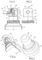
- the light bulb socket designated as a whole in FIG. 1 with 10 (usually an Edison socket of dimension E 27) essentially consists of a socket body 11 made of insulating material, in particular thermoplastic Plastic. Starting from the lamp side, the lampholder body 11 initially has a collar 12 which, in the exemplary embodiment, is provided with a screw thread 13 on the outside. This is followed by a circular cylindrical section 14 with a smooth outer surface, which ends remote from the lamp at a narrow, approximately 1 mm high step, to which a conical or conical section 16 connects.
- the conductor connection terminals and lamp contact tongues which are not shown and which establish the electrical connection between the mains conductors 27 in FIG. 2) and the lamp, are located in a mounting block 17 which - as can be clearly seen from FIG. 1 - has a narrow rectangular cross section.
- the transverse width 18 of the mounting block 17 is considerably narrower than the diameter of the cylindrical socket body section 14 and is only about a third thereof.
- the transverse length 19 of the building block 17 is at least slightly smaller than the diameter of the cylindrical section 14.
- coupling means 20 for snap-on connecting pieces such as holder, lamp body or the like are shown.
- the projection of this coupling means 20 is drawn exaggerated in FIG. 1, because the coupling means 20 should not protrude beyond the diameter of the cylindrical section 14 of the socket body 11.
- the narrow rectangular connector block 17, which goes without saying with the other socket body parts is integrally molded, sits transversely on the conical transition section 16, so that a parabolic transition edge 21 is formed on the two long sides of the mounting block 17 in accordance with the geometrical penetration of the smooth side walls of the mounting block 17 through the conical body 16.
- an internal thread 23 of size E 27 for screw fastening of the lamp base is arranged in the interior of the socket body 11 in the region of the externally cylindrical socket body section 14.
- the conical indentation 16, with a tip angle of approximately 90 ° largely corresponds to the conical base end of an incandescent lamp, ie the course of the inclined surface between the threaded end and the center contact.
- the socket body 11 thus optimally approximates the lamp geometry.
- the external thread 13 on the end collar 12 of the socket body 11 serves, as can be seen in FIGS. 2 and 4 and 5, for screwing on a dish-shaped reflector 24.
- the external thread 13 on the collar 12 is not mandatory because one also has a smooth collar, for example, for sliding on and So for the clamp-like mounting of a reflector or the like. could use.
- the space 25 is the interior of a pot-shaped housing 28 of a luminaire body, generally designated 29. It has a conductor entry 30 into which, as shown in Fig. 2, a connector, e.g. a trimmed tube 31 opens. This can be connected at its end, not shown, to a joint, a wall bracket and / or a base.
- the arrangement is cleverly and visually extremely appealing in such a way that the radial extension of the step 15 (FIG. 1) corresponds essentially to the wall thickness of the pot-like housing 28, so that the outer surface 32 of the pot-like housing 28 and the outer surface 33 of the cylindrical socket body section 14 in the same area can pass over or connect to one another (see in particular FIGS. 3 and 5).
- the bulb holder 15 is a functional and at the same time form-determining component of the spotlight shown overall in FIG. 2.
- the lampholder body 10 is not “swallowed” by the spotlight lamp housing, but only supplements it to form a complete lamp. This has considerable advantages.
- the pot-like housing 28 can be made very small in the longitudinal direction as well as in the circumference or in diameter and thus save material, and on the other hand an extremely compact spotlight is possible overall.
- the decisive diameter of the spotlight is no longer determined by the lamp body, but by the diameter of the socket body section 14 of the bulb holder 10, and the entire lamp is only a few millimeters longer than the bulb holder 10 itself, which is necessary for guiding the connecting conductors 27.
- the bulb holder 10 was cleverly designed in such a way that, combined with a pot-like housing 28 with conductor entry 30, it can immediately form a spotlight.
- the pot-like housing 28 and the bulb holder 10 are to be firmly connected to one another, although they can be detached if necessary.
- a non-rotatable connection between them is provided be, if only to ensure that the lamp can be screwed in and out without the conductors 27 twisting.
- this can have resilient locking elements, not shown, which can be locked with the coupling means 20 on the socket body 11.
- This latching can be designed in such a way that it not only acts in the axial direction, but also reliably prevents the parts that are coupled together from being able to be rotated relative to one another.
- the outer surfaces 32 and 33 of the lamp housing 29 and the socket body 11 do not have to be smooth.
- the molding of surface structures during the injection molding of the parts could even set special design accents.
Landscapes
- Fastening Of Light Sources Or Lamp Holders (AREA)
- Non-Portable Lighting Devices Or Systems Thereof (AREA)
- Vessels And Coating Films For Discharge Lamps (AREA)
Applications Claiming Priority (2)
| Application Number | Priority Date | Filing Date | Title |
|---|---|---|---|
| DE4343883 | 1993-12-22 | ||
| DE4343883A DE4343883C1 (de) | 1993-12-22 | 1993-12-22 | Glühlampenfassung |
Publications (2)
| Publication Number | Publication Date |
|---|---|
| EP0660462A1 true EP0660462A1 (fr) | 1995-06-28 |
| EP0660462B1 EP0660462B1 (fr) | 1996-04-10 |
Family
ID=6505803
Family Applications (1)
| Application Number | Title | Priority Date | Filing Date |
|---|---|---|---|
| EP94118546A Expired - Lifetime EP0660462B1 (fr) | 1993-12-22 | 1994-11-25 | Douille de lampe à incandescence et projecteur équipé d'une telle douille |
Country Status (5)
| Country | Link |
|---|---|
| EP (1) | EP0660462B1 (fr) |
| AT (1) | ATE136695T1 (fr) |
| DE (2) | DE4343883C1 (fr) |
| DK (1) | DK0660462T3 (fr) |
| ES (1) | ES2087786T3 (fr) |
Families Citing this family (1)
| Publication number | Priority date | Publication date | Assignee | Title |
|---|---|---|---|---|
| DE29618637U1 (de) * | 1996-10-25 | 1998-02-26 | Metalluk Bauscher Gmbh & Co Kg, 96050 Bamberg | Lampenfassung mit Führungsdurchgang |
Citations (5)
| Publication number | Priority date | Publication date | Assignee | Title |
|---|---|---|---|---|
| US4257664A (en) * | 1979-03-08 | 1981-03-24 | Eagle Electric Mfg. Co., Inc. | Screw socket for an electric lamp |
| DE8323973U1 (de) * | 1983-08-20 | 1983-12-15 | Brökelmann, Jaeger & Busse GmbH & Co, 5760 Arnsberg | Glühlampenfassung |
| DE3329475C1 (de) * | 1983-08-16 | 1985-02-07 | Brökelmann, Jaeger & Busse GmbH & Co, 5760 Arnsberg | Gluehlampenfassung |
| US4911656A (en) * | 1989-04-12 | 1990-03-27 | Yu Kuang Shih | Socket assembly for electric lamps |
| DE9305897U1 (de) * | 1993-04-20 | 1993-06-17 | Brökelmann, Jaeger & Busse GmbH & Co, 5760 Arnsberg | Lampenfassung |
Family Cites Families (1)
| Publication number | Priority date | Publication date | Assignee | Title |
|---|---|---|---|---|
| DE8800994U1 (de) * | 1988-01-28 | 1988-03-10 | Brökelmann, Jaeger & Busse GmbH & Co, 5760 Arnsberg | Lampenfassung |
-
1993
- 1993-12-22 DE DE4343883A patent/DE4343883C1/de not_active Expired - Fee Related
-
1994
- 1994-11-25 DE DE59400192T patent/DE59400192D1/de not_active Expired - Lifetime
- 1994-11-25 DK DK94118546.4T patent/DK0660462T3/da active
- 1994-11-25 EP EP94118546A patent/EP0660462B1/fr not_active Expired - Lifetime
- 1994-11-25 AT AT94118546T patent/ATE136695T1/de not_active IP Right Cessation
- 1994-11-25 ES ES94118546T patent/ES2087786T3/es not_active Expired - Lifetime
Patent Citations (5)
| Publication number | Priority date | Publication date | Assignee | Title |
|---|---|---|---|---|
| US4257664A (en) * | 1979-03-08 | 1981-03-24 | Eagle Electric Mfg. Co., Inc. | Screw socket for an electric lamp |
| DE3329475C1 (de) * | 1983-08-16 | 1985-02-07 | Brökelmann, Jaeger & Busse GmbH & Co, 5760 Arnsberg | Gluehlampenfassung |
| DE8323973U1 (de) * | 1983-08-20 | 1983-12-15 | Brökelmann, Jaeger & Busse GmbH & Co, 5760 Arnsberg | Glühlampenfassung |
| US4911656A (en) * | 1989-04-12 | 1990-03-27 | Yu Kuang Shih | Socket assembly for electric lamps |
| DE9305897U1 (de) * | 1993-04-20 | 1993-06-17 | Brökelmann, Jaeger & Busse GmbH & Co, 5760 Arnsberg | Lampenfassung |
Also Published As
| Publication number | Publication date |
|---|---|
| DK0660462T3 (da) | 1996-05-06 |
| EP0660462B1 (fr) | 1996-04-10 |
| DE4343883C1 (de) | 1995-07-06 |
| ES2087786T3 (es) | 1996-07-16 |
| DE59400192D1 (de) | 1996-05-15 |
| ATE136695T1 (de) | 1996-04-15 |
Similar Documents
| Publication | Publication Date | Title |
|---|---|---|
| EP0303561B1 (fr) | Lampe | |
| EP0557776A2 (fr) | Voyant lumineux | |
| DE3635808C2 (fr) | ||
| EP2650595B1 (fr) | Bande lumineuse avec luminaire | |
| EP0660462B1 (fr) | Douille de lampe à incandescence et projecteur équipé d'une telle douille | |
| DE4139905A1 (de) | Steckverbindung zur kontaktierung einer gasentladungslampe bei einem scheinwerfer | |
| EP0139075B1 (fr) | Ensemble projecteur | |
| DE9319755U1 (de) | Glühlampenfassung und damit ausgerüstete Strahlerleuchte | |
| DE4316271C2 (de) | Beleuchtungsvorrichtung für Kleinstleuchtstofflampen | |
| DE4343884C1 (de) | Glühlampenfassung | |
| DE20004194U1 (de) | Steckverbinder zur Leuchtenhalterung | |
| DE19922298B4 (de) | Befestigungssystem für eine Gasentladungslampe an einem Reflektor eines Scheinwerfers | |
| DE9305897U1 (de) | Lampenfassung | |
| DE1106868B (de) | Anschlusskappe fuer Neon-Leuchtroehren | |
| DE202023103963U1 (de) | Leuchte | |
| DE8134664U1 (de) | Isolationsteil für die Fassung eines elektrischen Gerätes | |
| DE819424C (de) | System von Feuchtraumleuchten | |
| DE2721310A1 (de) | Leuchte fuer eine leuchtenkette | |
| AT409904B (de) | Stromschiene und kupplungsvorrichtung | |
| EP0961077A2 (fr) | Dispositif porte-lampe pour luminaire à bras articulés comprenant une tête d'éclairage | |
| DE20021307U1 (de) | Elektrische Leuchte | |
| DE20313185U1 (de) | Lampen-Fassung | |
| DE4316273A1 (de) | Leuchtengehäuse für kleine Leuchtstofflampen | |
| DE19911347A1 (de) | Leuchte für eine langgestreckte Lampe | |
| DE19901077A1 (de) | Installationssystem für Leuchten |
Legal Events
| Date | Code | Title | Description |
|---|---|---|---|
| PUAI | Public reference made under article 153(3) epc to a published international application that has entered the european phase |
Free format text: ORIGINAL CODE: 0009012 |
|
| AK | Designated contracting states |
Kind code of ref document: A1 Designated state(s): AT BE CH DE DK ES FR GB IT LI NL SE |
|
| 17P | Request for examination filed |
Effective date: 19950710 |
|
| 17Q | First examination report despatched |
Effective date: 19950918 |
|
| ITF | It: translation for a ep patent filed | ||
| GRAH | Despatch of communication of intention to grant a patent |
Free format text: ORIGINAL CODE: EPIDOS IGRA |
|
| GRAA | (expected) grant |
Free format text: ORIGINAL CODE: 0009210 |
|
| AK | Designated contracting states |
Kind code of ref document: B1 Designated state(s): AT BE CH DE DK ES FR GB IT LI NL SE |
|
| REF | Corresponds to: |
Ref document number: 136695 Country of ref document: AT Date of ref document: 19960415 Kind code of ref document: T |
|
| REG | Reference to a national code |
Ref country code: DK Ref legal event code: T3 |
|
| REF | Corresponds to: |
Ref document number: 59400192 Country of ref document: DE Date of ref document: 19960515 |
|
| ET | Fr: translation filed | ||
| GBT | Gb: translation of ep patent filed (gb section 77(6)(a)/1977) |
Effective date: 19960503 |
|
| REG | Reference to a national code |
Ref country code: CH Ref legal event code: NV Representative=s name: MOINAS KIEHL SAVOYE & CRONIN |
|
| REG | Reference to a national code |
Ref country code: ES Ref legal event code: BA2A Ref document number: 2087786 Country of ref document: ES Kind code of ref document: T3 |
|
| REG | Reference to a national code |
Ref country code: ES Ref legal event code: FG2A Ref document number: 2087786 Country of ref document: ES Kind code of ref document: T3 |
|
| PLBE | No opposition filed within time limit |
Free format text: ORIGINAL CODE: 0009261 |
|
| STAA | Information on the status of an ep patent application or granted ep patent |
Free format text: STATUS: NO OPPOSITION FILED WITHIN TIME LIMIT |
|
| 26N | No opposition filed | ||
| REG | Reference to a national code |
Ref country code: GB Ref legal event code: IF02 |
|
| PGFP | Annual fee paid to national office [announced via postgrant information from national office to epo] |
Ref country code: DK Payment date: 20041112 Year of fee payment: 11 |
|
| PGFP | Annual fee paid to national office [announced via postgrant information from national office to epo] |
Ref country code: BE Payment date: 20041117 Year of fee payment: 11 |
|
| PGFP | Annual fee paid to national office [announced via postgrant information from national office to epo] |
Ref country code: AT Payment date: 20041119 Year of fee payment: 11 |
|
| PGFP | Annual fee paid to national office [announced via postgrant information from national office to epo] |
Ref country code: FR Payment date: 20041124 Year of fee payment: 11 |
|
| PGFP | Annual fee paid to national office [announced via postgrant information from national office to epo] |
Ref country code: NL Payment date: 20041130 Year of fee payment: 11 Ref country code: CH Payment date: 20041130 Year of fee payment: 11 |
|
| PGFP | Annual fee paid to national office [announced via postgrant information from national office to epo] |
Ref country code: SE Payment date: 20050131 Year of fee payment: 11 |
|
| PG25 | Lapsed in a contracting state [announced via postgrant information from national office to epo] |
Ref country code: AT Free format text: LAPSE BECAUSE OF NON-PAYMENT OF DUE FEES Effective date: 20051125 |
|
| PG25 | Lapsed in a contracting state [announced via postgrant information from national office to epo] |
Ref country code: SE Free format text: LAPSE BECAUSE OF NON-PAYMENT OF DUE FEES Effective date: 20051126 |
|
| PG25 | Lapsed in a contracting state [announced via postgrant information from national office to epo] |
Ref country code: LI Free format text: LAPSE BECAUSE OF NON-PAYMENT OF DUE FEES Effective date: 20051130 Ref country code: DK Free format text: LAPSE BECAUSE OF NON-PAYMENT OF DUE FEES Effective date: 20051130 Ref country code: CH Free format text: LAPSE BECAUSE OF NON-PAYMENT OF DUE FEES Effective date: 20051130 Ref country code: BE Free format text: LAPSE BECAUSE OF NON-PAYMENT OF DUE FEES Effective date: 20051130 |
|
| PG25 | Lapsed in a contracting state [announced via postgrant information from national office to epo] |
Ref country code: NL Free format text: LAPSE BECAUSE OF NON-PAYMENT OF DUE FEES Effective date: 20060601 |
|
| REG | Reference to a national code |
Ref country code: DK Ref legal event code: EBP |
|
| REG | Reference to a national code |
Ref country code: CH Ref legal event code: PL |
|
| EUG | Se: european patent has lapsed | ||
| PG25 | Lapsed in a contracting state [announced via postgrant information from national office to epo] |
Ref country code: FR Free format text: LAPSE BECAUSE OF NON-PAYMENT OF DUE FEES Effective date: 20060731 |
|
| NLV4 | Nl: lapsed or anulled due to non-payment of the annual fee |
Effective date: 20060601 |
|
| REG | Reference to a national code |
Ref country code: FR Ref legal event code: ST Effective date: 20060731 |
|
| BERE | Be: lapsed |
Owner name: *BROKELMANN JAEGER & BUSSE G.M.B.H. & CO. Effective date: 20051130 |
|
| PGFP | Annual fee paid to national office [announced via postgrant information from national office to epo] |
Ref country code: GB Payment date: 20101111 Year of fee payment: 17 Ref country code: IT Payment date: 20101027 Year of fee payment: 17 |
|
| PGFP | Annual fee paid to national office [announced via postgrant information from national office to epo] |
Ref country code: ES Payment date: 20101130 Year of fee payment: 17 |
|
| REG | Reference to a national code |
Ref country code: DE Ref legal event code: R082 Ref document number: 59400192 Country of ref document: DE Representative=s name: PATENTANWAELTE OSTRIGA, SONNET, WIRTHS & VORWE, DE |
|
| GBPC | Gb: european patent ceased through non-payment of renewal fee |
Effective date: 20111125 |
|
| PG25 | Lapsed in a contracting state [announced via postgrant information from national office to epo] |
Ref country code: IT Free format text: LAPSE BECAUSE OF NON-PAYMENT OF DUE FEES Effective date: 20111125 |
|
| PG25 | Lapsed in a contracting state [announced via postgrant information from national office to epo] |
Ref country code: GB Free format text: LAPSE BECAUSE OF NON-PAYMENT OF DUE FEES Effective date: 20111125 |
|
| REG | Reference to a national code |
Ref country code: ES Ref legal event code: FD2A Effective date: 20130604 |
|
| PG25 | Lapsed in a contracting state [announced via postgrant information from national office to epo] |
Ref country code: ES Free format text: LAPSE BECAUSE OF NON-PAYMENT OF DUE FEES Effective date: 20111126 |
|
| PGFP | Annual fee paid to national office [announced via postgrant information from national office to epo] |
Ref country code: DE Payment date: 20130926 Year of fee payment: 20 |
|
| REG | Reference to a national code |
Ref country code: DE Ref legal event code: R071 Ref document number: 59400192 Country of ref document: DE |