EP0660604A2 - Précorrection d'une porteuse audio dans un système d'amplification commun pour les porteuses vidéo et audio - Google Patents
Précorrection d'une porteuse audio dans un système d'amplification commun pour les porteuses vidéo et audio Download PDFInfo
- Publication number
- EP0660604A2 EP0660604A2 EP94309715A EP94309715A EP0660604A2 EP 0660604 A2 EP0660604 A2 EP 0660604A2 EP 94309715 A EP94309715 A EP 94309715A EP 94309715 A EP94309715 A EP 94309715A EP 0660604 A2 EP0660604 A2 EP 0660604A2
- Authority
- EP
- European Patent Office
- Prior art keywords
- signal
- aural
- video
- visual
- corrector
- Prior art date
- Legal status (The legal status is an assumption and is not a legal conclusion. Google has not performed a legal analysis and makes no representation as to the accuracy of the status listed.)
- Granted
Links
Images




Classifications
-
- H—ELECTRICITY
- H04—ELECTRIC COMMUNICATION TECHNIQUE
- H04N—PICTORIAL COMMUNICATION, e.g. TELEVISION
- H04N7/00—Television systems
- H04N7/04—Systems for the transmission of one television signal, i.e. both picture and sound, by a single carrier
-
- H—ELECTRICITY
- H04—ELECTRIC COMMUNICATION TECHNIQUE
- H04N—PICTORIAL COMMUNICATION, e.g. TELEVISION
- H04N5/00—Details of television systems
- H04N5/38—Transmitter circuitry for the transmission of television signals according to analogue transmission standards
-
- H—ELECTRICITY
- H04—ELECTRIC COMMUNICATION TECHNIQUE
- H04N—PICTORIAL COMMUNICATION, e.g. TELEVISION
- H04N5/00—Details of television systems
- H04N5/44—Receiver circuitry for the reception of television signals according to analogue transmission standards
- H04N5/60—Receiver circuitry for the reception of television signals according to analogue transmission standards for the sound signals
- H04N5/62—Intercarrier circuits, i.e. heterodyning sound and vision carriers
Definitions
- This invention relates to the art of common amplification television transmitters wherein aural and visual signals are commonly amplified.
- U.S. Patent No. 5,198,904 proposes to correct the unwanted distortion of the aural carrier by predistorting phase and amplitude components of tile aural carrier so as to be directly opposite to the unwanted distortions caused by the common amplification in a television transmitter.
- the above referenced samples the baseband video signal prior to the signal being used to modulate a visual IF carrier signal.
- the sampled baseband video signal is delayed by a video delay to compensate for the delays that are introduced in an IF vision modulator to which the baseband video signal is also supplied for modulating a visual carrier signal.
- the delayed baseband video signal is then applied to a complementary nonlinear amplifier which provides a phase correction signal and an amplitude correction signal.
- correction signals are supplied to an amplitude and phase modulator which also receives the aural carrier.
- the aural carrier is modulated by the amplitude and phase correction signals to provide a modified aural signal which is summed with the output of the IF vision modulator.
- the sampled baseband video signal patent has a relatively flat amplitude response over the baseband video spectrum.
- the cross-modulation on the aural carrier has two different sideband levels.
- the high level is created by the double sideband region of the visual spectrum, that is 10.75 MHz about the visual carrier frequency.
- the half amplitude levels extending to ⁇ 4.2 MHz about the aural carrier are due to the single sideband region (0.75 - 4.2 MHz) of the visual spectrum. Therefore, when modulating the aural carrier with frequency and amplitude correction signals based on the flat spectral response (of the baseband signal) an incomplete cancellation of the cross- niodulation will result.
- Another problem noted is the cost and complexity of a video delay circuit which serves to delay the baseband video signal prior to developing the correction signals. This video delay serves to compensate for the delays introduced in the IF vision modulator and filter where the baseband video signal modulates the visual IF carrier signal.
- Such delay circuits are expensive and, consequently, it is desirable to design circuitry to minimize or eliminate the use of such circuits.
- An object of the present invention is to provide an improved aural correction system wherein a video signal is obtained for use in developing amplitude and phase correction signals with the video signal being obtained from a location after the IF vision modulator so as to eliminate the need for a video delay circuit.
- a further object of the present invention to provide an aural correction circuit wherein the video signal employed for providing phase and amplitude correction signals is obtained from a point subsequent to the IF vision modulator so that the sampled video signal includes visual carrier characteristics and exhibits a first high level amplitude at frequencies in the double sideband region of the frequency spectrum and a second lower level amplitude at frequencies extending therefrom into the single sideband regions of the frequency spectrum. This is done to provide correction which is opposite to the cross-modulation over the full spectrum thereof to thereby achieve full cancellation O ⁇ the cross-modulation on the aural carrier.
- the present invention includes apparatus for precorrecting an aural carrier signal in a common amplifier system in which the precorrecting serves to minimize cros-modulation distortion of said aural carrier signal caused by said common amplifier system and characterized by means for receiving a moduleated visual signal comprised of a visual carrier signal modulated by a video baseband signal and providing therefrom a sampled video signal; aural corrector means for receiving said sampled video signal and providing therefrom a phase correction signal and an amplitude correction signal, phase and amplitude modulating means for receiving said aural carrier signal and modulating same with said phase and amplitude correction signals to provide a precorrected aural signal, and means for comgining said visual signal with said precorrected aural signal to provide a combined signal.
- the precorrecting apparatus includes means for receiving a modulated visual signal and which is comprised of a visual carrier signal modulated by a video baseband signal, and providing therefrom a sampled video signal.
- the sampled video signal is received by an aural corrector which provides therefrom a phase correction signal and an amplitude correction signal.
- These signals are supplied to phase and amplitude modulation circuitry for modulating an aural carrier with the phase and amplitude correction signals to provide a precorrected aural signal which is opposite the cross-modulation distortion.
- the video signal and the precorrected aural signal are combined and commonly amplified in a manner to cancel the cross-modulation.
- Fig. 1 illustrates a prior art aural carrier correction circuit based on that shown in the specification of U.S. Patent No. 5,198,904.
- the character references shown in Fig. 1 herein correspond to those employed in Fig. 1 in the specification U.S. Patent No. 5,198,904.
- an aural carrier correction system 11 in conjunction with a television transmitter, partly shown at 12.
- the transmitter includes an IF vision modulator 19 followed by a summing circuit 21 and an IF system corrector 23.
- the system 11 includes a video delay 13, a processor 15 and an amplitude and phase modulator 17.
- the IF vision modulator receives a baseband video input signal 25 which is used to modulate a visual IF carrier signal 17 to provide an IF visual signal 26.
- the IF visual signal 26 is summed with a modified IF aural signal 28 at the summing circuit 21 and the combined signal 35 is then supplied to an IF system corrector 23.
- the baseband video signal 25 is also used as a sample point to supply a sampled baseband video signal to the aural corrector system 11.
- System 11 includes a complementary amplifier which uses the sampled baseband video signal to provide an amplitude correction signal 29 and a phase correction signal 31. These signals modulate the aural carrier in the modulator circuit 17 which supplies a modified IF aural signal 28 to the summer 21. Since the baseband video signal 25 is delayed by the IF vision modulator 19, a similar delay is provided by the video delay circuit 13 in the aural corrector system 11 so that there is a coincidence between the modified IF aural signal 28 and the visual signal 26 outputted by the IF vision modulator 19. These two signals 26 and 28 are summed by the summer 21 and supplied to the IF system corrector circuit 23.
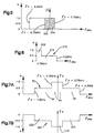
- Fig. 2 illustrates curve 50 which represents the sampled baseband video signal and which has a relatively flat level over the baseband spectrum being illustrated.
- Fig. 3A illustrates a curve 52 of the cross-modulation on the aural carrier F A over the frequency spectrum from F A -4.2 MHz to F A + 4.2MHz.
- This includes a central or double amplitude region 54 due to the double sideband region of the visual signal immediately surrounding the carrier frequency F A and lower amplitude regions 56 and 58.
- It is this cross-modulation 52 over the entire cross-modulation spectrum that is desired to be cancelled by the aural corrector 11.
- the present invention is directed toward improvements over that disclosed in the specification of patent No. 5,198,904 so as to avoid the over correction noted with respect to the single sideband portions 66 and 68 of curve 62 in Fig. 3C and also to eliminate the need for employing a video delay such as delay 13 in the above mentioned specification of U.S. No. 5,198,904 patent.
- a baseband video input signal 99 is supplied to an IF vision modulator 100 which also receives a visual IF carrier signal 101.
- the modulated visual signal is then precorrected for distortions introduced in the power amplifier in a conventional IF linearity corrector circuit 102 (having adjustment means, not shown) with the corrected visual signal being supplied to an automatic gain control circuit 104.
- the automatic gain control (AGC) circuit 104 provides a constant amplitude video signal used in the aural signal correction circuit to be described below.
- the video signal obtained from the automatic gain control circuit (AGA) 104 is supplied to a filter and delay circuit 106, the purpose of which is to equalize the video processing time in processor 114, the output of which is supplied to a summing circuit 108.
- the video signal from the automatic gain control circuit 104 is demodulated or detected by a detector 110 with the detected video signal then being supplied to a processor 114 which provides both a phase correction signal 115 and an amplitude correction signal 117.
- the aural IF carrier input signal 119 is applied to a phase modulator 116 and then to an amplitude modulator 118 where the aural carrier is modulated by the phase correction signal 115 and the amplitude correction signal 117 with the output being supplied to an automatic gain control (AGC) 120.
- AGC automatic gain control
- the precorrected or modified carrier signal is then supplied to the summing circuit 108 with the output thereof, as in the case of the circuit of Fig. 1, being commonly amplified and transmitted.
- the video signal employed by the video processor 114 is sampled by detector 110 which is downstream from the vision modulator 100 and from the IF linearity corrector 102. Consequently, the sampled video signal in Fig, 4 is taken from an entirely different sample point in tile frequency spectrum from that of the sample obtained from the baseband video input signal 25 in the prior art of Fig. 1. Also, the linearity corrector 102 in Fig. 4 is upstream from the summer 108 and, consequently, visual correction is made independently of aural correction. In Fig. 1, the visual correction is made in corrector 23 after the visual carrier has been summed with the modified aural carrier.
- Fig. 5 illustrates a curve 200 showing amplitude with respect to frequency of a signal taken from the output of the IF vision modulator 100 in Fig. 4
- This signal represents the vestigial sideband filtered modulated visual IF spectrum.
- This signal shows lower and upper double sideband regions 202 and 204 on either side of the visual carrier frequency F v .
- the sampled video signal appears as curve 210 in Fig. 6 having a higher magnitude portion 208 at the double sideband portion and a lower magnitude portion 212 extending from 0.75 Mhz out to approximately 4.2 MHz.
- This sampled video signal differs substantially from that of the sampled video signal represented by curve 50 in Fig. 2.
- Fig. 7 which includes Figs. 7A and 7B.
- Fig. 7A is a repeat of Fig. 3A which illustrates the cross-modulation 52 on the aural carrier F A including that due to the visual single sideband portions at 56 and 58 and that due to the visual double sideband portion at 54. It is this cross-modulation that should be cancelled by the correcting signals.
- the sampled video signal spectrum illustrated by the curve 210 in Fig.6 is employed by the corrector circuits herein for modulating the aural IF carrier signal 119 so as to obtain a modulated carrier appearing as curve 220 in Fig. 78.
- Curve 220 includes half amplitude portions 222 and 224 and a full sideband portion 226, the negative sign indicating that the spectrum is in antiphase. It is seen that when the cross-modulation curve 52 is combined with the correction curve 220, complete cancellation results in accordance with the present invention.
- the circuitry of Fig. 4 to accomplish the foregoing will now be described in greater detail with the expanded circuitry illustrated in Fig. 8.
- the visual corrector circuit 102 corresponds with the IF linearity corrector circuit 102 in Fig. 4 and serves to receive the output of the IF vision modulator 100. That signal is a visual IF input signal which includes the visual carrier signal modulated by the baseband video signal 99.
- the visual corrector circuit 102 includes conventional corrector circuits 300 and 302 which are adjustable and serve to provide correction signals for the white level and the black-sync levels.
- the output of the visual corrector circuit 102 is supplied to an automatic gain control 104 that serves to keep the black level of the detected video signal constant.
- the modulated visual IF signal supplied to corrector 102 is predistorted by the visual correctors 300 and 302 in a way which will aid in the correction of the aural carrier. This predistortion is created by the visual correctors 300 and 302 in the process of "mopping up" residual video distortion present on the visual output of the host transmitter.
- the automatic gain control circuit 104 keeps the modulated visual IF level constant. The output of the automatic gain control 104 is detected by the video detector 110.
- the sampling for the gain control circuit is obtained during the video horizontal blanking period at the output of the video detector 110.
- the sampled video signal may take the form O ⁇ spectrum 210 in Fig. 6 including a first high level portion 208 and a lower level portion 212 as opposed to the relatively flat spectral response as shown by curve 50 in Fig. 2 and which is representative of the sampled video signal employed in the Ta et al. patent discussed hereinbefore.
- the sampled video signal in Figs. 4 and 8 is taken from a point after the visual IF carrier signal 101 has been modulated by the baseband video input signal 99 so as to provide an output signal which generally takes the term of curve 200 shown in Fig. 5.
- Curve 200 represents the vestigial sideband filtered, modulated visual IF spectrum which, when detected by the video detector 110, provides a signal with a spectrum as shown by waveform 210 in Fig. 6.
- the higher level portion 208 in Fig. 6 from 0 to 0.75 MHz is due to the fact that for a baseband modulating frequency up to 0.75 MHz, a double sideband output exists due to the shape of the IF filter used in the IF vision modulator 19 of Fig. 1 or in the IF vision modulator 100 in Fig. 4.
- the sampled video signal obtained from the video detector 110 is negative in that the synchronization pulses are positive going and the picture information is negative going. This is considered a negative video signal and is inverted by an inverter amplifier 304 inside the video processor 114 (see Fig. 8).
- This video processor 114 as shown in Fig. 8 also includes a negative video signal clipper circuit 306, a positive video clipper circuit 308, and a summing circuit 310 for summing the outputs of the clipper circuits 306 and 308 and supplying the amplitude correction signal 117 to the amplitude modulator 118.
- the video processor also includes an analog multiplier 31 2 which multiplies the negative video signal obtained from the video detector 110 and the positive video signal obtained from inverter amplifier 304 to provide the phase correction signal 115 that is supplied to the phase modulator 116.
- the video clipper circuits 306 and 308 are conventional in the art and each includes an onset adjuster, a slope adjuster and an amplitude level adjuster.
- the adjustable clipper circuit 306 includes an onset adjuster taking the form of potentiometer 320, a slope adjuster taking the form of a potentiometer 322 and a level adjuster taking the form of a potentiometer 324.
- the positive video signal clipper 308 includes an onset adjuster taking the form of a potentiometer 326, a slope adjuster taking the form of a potentiometer 328, and a level adjuster taking the form of a potentiometer 330.
- the sampled or detected video signals provided by the video detector 110 are distorted or precorrected by the clipper circuits 306 and 308 where the onset or clip points and the slopes are adjustable using the onset and slope adjusters.
- the detected positive and negative video signals are distorted by the clipper circuits 306 and 308 where the clip points or onset points as well as the slopes are adjustable.
- the outputs of the clipper circuits 306 and 308 are also adjustable in level by the level potentiometers 324 and 330 prior to being summed in the summation circuit 310.
- the summation circuit 310 produces the correcting or modulating signal 117 which is supplied to the amplitude modulator 118 to predistort or precorrect the aural carrier signal. This signal appears as waveform 354 in Fig. 9C. It is to be noted particularly from Fig. 90 that the correcting or modulating signal may have a zero, positive or negative picture signals well as a zero, positive or negative going sync pulse as required by the transmitter being corrected.
- the negative and positive video signals are also illustrated in Figs. 10A and 10B as curves 360 and 362. These signals are supplied to the analog multiplier 312 (Fig. 8) to provide an output signal 115 which is supplied to the phase modulator 116.
- the effect of multiplying the positive and negative video signals is indicated by the curve 354 in Fig. 100.
- This curve 364 shows curved positive and negative portions 366 and 368 which are the result of the multiplying of the two signal in the multiplier 312.
- This predistorted or precorrected modulating signal 115 is supplied to the phase modulator 116 for precorrecting the aural carrier signal.
- the phase modulator 116 provides very little amplitude modulation and the amplitude modulator 118 is of a doubly balanced type.
- the output of the amplitude modulator 118 is supplied to an aural automatic gain control circuit (AGC) 120.
- AGC aural automatic gain control circuit
- the AGC circuit 120 serves to ensure that the aural power is held constant during the adjusting procedure.
- the carrier level at a time corresponding to the visual back porch of the video signal is used as the reference.
- a bandpass filter 106 is incorporated in the visual signal IF path just prior to the aural-video combiner 108. This filter provides a delay which compensates the processing time in the detector and video circuits thereby ensuring that the aural correction is correctly timed relative to the visual modulation and the sidebands are in correctly phased for cancellation.
- a circuit for precorrecting an aural carrier signal in a common amplifier system in a television transmitter wherein an aural frequency signal and a visual signal are commonly amplified.
- the precorrecting serves to minimize cross-modulation distortion of the aural carrier caused by the common amplification.
- a visual carrier signal is modulated by a video baseband signal to provide a modulated video signal from which there is provided a sampled video signal. This sampled video signal is supplied to an aural corrector which provides from the sampled video signal a phase correction signal and an amplitude correction signal.
Landscapes
- Engineering & Computer Science (AREA)
- Multimedia (AREA)
- Signal Processing (AREA)
- Amplitude Modulation (AREA)
- Television Systems (AREA)
- Picture Signal Circuits (AREA)
- Television Receiver Circuits (AREA)
Applications Claiming Priority (2)
| Application Number | Priority Date | Filing Date | Title |
|---|---|---|---|
| US08/173,553 US5418578A (en) | 1993-12-27 | 1993-12-27 | Precorrecting an aural carrier signal in a common amplifier system |
| US173553 | 1993-12-27 |
Publications (3)
| Publication Number | Publication Date |
|---|---|
| EP0660604A2 true EP0660604A2 (fr) | 1995-06-28 |
| EP0660604A3 EP0660604A3 (fr) | 1995-08-16 |
| EP0660604B1 EP0660604B1 (fr) | 1998-09-16 |
Family
ID=22632538
Family Applications (1)
| Application Number | Title | Priority Date | Filing Date |
|---|---|---|---|
| EP94309715A Expired - Lifetime EP0660604B1 (fr) | 1993-12-27 | 1994-12-22 | Précorrection d'une porteuse audio dans un système d'amplification commun pour les porteuses vidéo et audio |
Country Status (5)
| Country | Link |
|---|---|
| US (1) | US5418578A (fr) |
| EP (1) | EP0660604B1 (fr) |
| JP (1) | JPH07288752A (fr) |
| CA (1) | CA2139071A1 (fr) |
| DE (1) | DE69413369T2 (fr) |
Families Citing this family (8)
| Publication number | Priority date | Publication date | Assignee | Title |
|---|---|---|---|---|
| US5751824A (en) * | 1994-09-23 | 1998-05-12 | Lucent Technologies Inc. | Method of stabilizing the level of an audio signal in television broadcasting |
| US6081599A (en) * | 1997-12-01 | 2000-06-27 | Tresness Irrevocable Patent Trust | Saw television scrambling system |
| US20030112370A1 (en) * | 2001-12-18 | 2003-06-19 | Chris Long | Adaptive expanded information capacity for communications systems |
| FR2778810B1 (fr) * | 1998-05-14 | 2000-07-28 | Sagem | Dispositif d'amplification a voie commune pour la television |
| US6515711B1 (en) | 1998-05-27 | 2003-02-04 | Harris Corporation | System for correcting an aural carrier signal |
| US6868372B2 (en) | 2000-04-12 | 2005-03-15 | Home Box Office, Inc. | Image and audio degradation simulator |
| WO2002060049A2 (fr) * | 2001-01-23 | 2002-08-01 | Telefonaktiebolaget Lm Ericsson (Publ) | Procede et appareil de compensation d'effets de transmodulation |
| RU2409897C1 (ru) * | 2009-05-18 | 2011-01-20 | Самсунг Электроникс Ко., Лтд | Кодер, передающее устройство, система передачи и способ кодирования информационных объектов |
Family Cites Families (7)
| Publication number | Priority date | Publication date | Assignee | Title |
|---|---|---|---|---|
| FR2553947B1 (fr) * | 1983-10-21 | 1985-12-13 | Lgt Lab Gen Telecomm | Dispositif de precorrection automatique des non-linearites dans une chaine d'amplification de puissance et emetteur de television comportant un tel dispositif |
| FR2558673B1 (fr) * | 1984-01-20 | 1986-04-25 | Thomson Csf | Emetteur de television comportant un klystron commun pour l'image et le son |
| US4591915A (en) * | 1984-04-18 | 1986-05-27 | Oak Industries Inc. | Remote volume control by means of frequency modulation feedback loop |
| IT1215370B (it) * | 1987-02-26 | 1990-02-08 | Gtg Ora Siemens Telecomunicazi | Linearizzatore per amplificatore di potenza a microonde. |
| US4974087A (en) * | 1989-04-13 | 1990-11-27 | Rca Licensing Corporation | Parallel sound if with reference carrier derived from quasi-synchronous video detector |
| US5198904A (en) * | 1991-02-25 | 1993-03-30 | Comark Communications, Inc. | Aural carrier correction system and method |
| JPH05161081A (ja) * | 1991-11-21 | 1993-06-25 | Alps Electric Co Ltd | Rfモジュレータ |
-
1993
- 1993-12-27 US US08/173,553 patent/US5418578A/en not_active Expired - Fee Related
-
1994
- 1994-12-22 EP EP94309715A patent/EP0660604B1/fr not_active Expired - Lifetime
- 1994-12-22 DE DE69413369T patent/DE69413369T2/de not_active Expired - Fee Related
- 1994-12-23 CA CA002139071A patent/CA2139071A1/fr not_active Abandoned
- 1994-12-27 JP JP6326005A patent/JPH07288752A/ja not_active Ceased
Also Published As
| Publication number | Publication date |
|---|---|
| EP0660604B1 (fr) | 1998-09-16 |
| DE69413369T2 (de) | 1999-03-11 |
| CA2139071A1 (fr) | 1995-06-28 |
| US5418578A (en) | 1995-05-23 |
| JPH07288752A (ja) | 1995-10-31 |
| EP0660604A3 (fr) | 1995-08-16 |
| DE69413369D1 (de) | 1998-10-22 |
Similar Documents
| Publication | Publication Date | Title |
|---|---|---|
| EP0441580B1 (fr) | Circuit pour la réduction de distorsions produites par un amplificateur de puissance de fréquence radio | |
| US4670789A (en) | Television transmitter | |
| US4962426A (en) | Dynamic noise reduction circuit for image luminance signal | |
| EP0454355A2 (fr) | Appareil de traitement de signal d'image pour l'accentuation de contours | |
| EP0660604B1 (fr) | Précorrection d'une porteuse audio dans un système d'amplification commun pour les porteuses vidéo et audio | |
| EP1097508B1 (fr) | Procede et dispositif permettant de compenser la distorsion dans les modulateurs iq | |
| JPS63185177A (ja) | 周波数変調回路 | |
| EP0149319A2 (fr) | Circuit haute fréquence | |
| US5218438A (en) | Picture aperture correction circuit | |
| US5406336A (en) | Contrast and brightness control whereby both are based on the detected difference between a fixed black level in the video signal and the black peak value | |
| US5198904A (en) | Aural carrier correction system and method | |
| US6081599A (en) | Saw television scrambling system | |
| JPH0262971B2 (fr) | ||
| US4197556A (en) | Hue correction circuit | |
| US6515711B1 (en) | System for correcting an aural carrier signal | |
| US6078720A (en) | Apparatus for copying a signal recorded on a video recording medium without demodulation | |
| KR100320428B1 (ko) | 디지털 dv 중계기의 왜곡 보상 방법 및 시스템 | |
| US2896014A (en) | Gamma-correction apparatus | |
| KR900005187B1 (ko) | 수직윤곽 보정장치 | |
| JP2506681Y2 (ja) | 非直線性補正回路 | |
| JPH0568185A (ja) | デイスパーサル信号除去装置 | |
| JP2755163B2 (ja) | 送信機の歪補償装置 | |
| JPH09181787A (ja) | 無線機 | |
| EP0431875A2 (fr) | Dispositif d'addition d'un signal de dispersion d'énergie et dispositif pour supprimer ce signal | |
| KR20010059728A (ko) | 브이에스비 자동 선형화 장치 |
Legal Events
| Date | Code | Title | Description |
|---|---|---|---|
| PUAI | Public reference made under article 153(3) epc to a published international application that has entered the european phase |
Free format text: ORIGINAL CODE: 0009012 |
|
| PUAL | Search report despatched |
Free format text: ORIGINAL CODE: 0009013 |
|
| AK | Designated contracting states |
Kind code of ref document: A2 Designated state(s): DE FR GB IT SE |
|
| AK | Designated contracting states |
Kind code of ref document: A3 Designated state(s): DE FR GB IT SE |
|
| 17P | Request for examination filed |
Effective date: 19960216 |
|
| GRAG | Despatch of communication of intention to grant |
Free format text: ORIGINAL CODE: EPIDOS AGRA |
|
| 17Q | First examination report despatched |
Effective date: 19971212 |
|
| GRAG | Despatch of communication of intention to grant |
Free format text: ORIGINAL CODE: EPIDOS AGRA |
|
| GRAH | Despatch of communication of intention to grant a patent |
Free format text: ORIGINAL CODE: EPIDOS IGRA |
|
| GRAH | Despatch of communication of intention to grant a patent |
Free format text: ORIGINAL CODE: EPIDOS IGRA |
|
| GRAA | (expected) grant |
Free format text: ORIGINAL CODE: 0009210 |
|
| AK | Designated contracting states |
Kind code of ref document: B1 Designated state(s): DE FR GB IT SE |
|
| REF | Corresponds to: |
Ref document number: 69413369 Country of ref document: DE Date of ref document: 19981022 |
|
| ET | Fr: translation filed | ||
| PLBE | No opposition filed within time limit |
Free format text: ORIGINAL CODE: 0009261 |
|
| STAA | Information on the status of an ep patent application or granted ep patent |
Free format text: STATUS: NO OPPOSITION FILED WITHIN TIME LIMIT |
|
| 26N | No opposition filed | ||
| PGFP | Annual fee paid to national office [announced via postgrant information from national office to epo] |
Ref country code: FR Payment date: 20011130 Year of fee payment: 8 |
|
| PGFP | Annual fee paid to national office [announced via postgrant information from national office to epo] |
Ref country code: SE Payment date: 20011203 Year of fee payment: 8 |
|
| PGFP | Annual fee paid to national office [announced via postgrant information from national office to epo] |
Ref country code: GB Payment date: 20011204 Year of fee payment: 8 Ref country code: DE Payment date: 20011204 Year of fee payment: 8 |
|
| REG | Reference to a national code |
Ref country code: GB Ref legal event code: IF02 |
|
| PG25 | Lapsed in a contracting state [announced via postgrant information from national office to epo] |
Ref country code: GB Free format text: LAPSE BECAUSE OF NON-PAYMENT OF DUE FEES Effective date: 20021222 |
|
| PG25 | Lapsed in a contracting state [announced via postgrant information from national office to epo] |
Ref country code: SE Free format text: LAPSE BECAUSE OF NON-PAYMENT OF DUE FEES Effective date: 20021223 |
|
| PG25 | Lapsed in a contracting state [announced via postgrant information from national office to epo] |
Ref country code: DE Free format text: LAPSE BECAUSE OF NON-PAYMENT OF DUE FEES Effective date: 20030701 |
|
| EUG | Se: european patent has lapsed | ||
| GBPC | Gb: european patent ceased through non-payment of renewal fee |
Effective date: 20021222 |
|
| PG25 | Lapsed in a contracting state [announced via postgrant information from national office to epo] |
Ref country code: FR Free format text: LAPSE BECAUSE OF NON-PAYMENT OF DUE FEES Effective date: 20030901 |
|
| REG | Reference to a national code |
Ref country code: FR Ref legal event code: ST |
|
| PG25 | Lapsed in a contracting state [announced via postgrant information from national office to epo] |
Ref country code: IT Free format text: LAPSE BECAUSE OF NON-PAYMENT OF DUE FEES Effective date: 20051222 |