EP0661833A1 - Basisband-Amplitude/Frequenz-Charakteristikschätzer - Google Patents
Basisband-Amplitude/Frequenz-Charakteristikschätzer Download PDFInfo
- Publication number
- EP0661833A1 EP0661833A1 EP94403031A EP94403031A EP0661833A1 EP 0661833 A1 EP0661833 A1 EP 0661833A1 EP 94403031 A EP94403031 A EP 94403031A EP 94403031 A EP94403031 A EP 94403031A EP 0661833 A1 EP0661833 A1 EP 0661833A1
- Authority
- EP
- European Patent Office
- Prior art keywords
- signal
- demodulation
- components
- estimator
- frequency
- Prior art date
- Legal status (The legal status is an assumption and is not a legal conclusion. Google has not performed a legal analysis and makes no representation as to the accuracy of the status listed.)
- Granted
Links
- 230000003111 delayed effect Effects 0.000 claims description 16
- 238000001914 filtration Methods 0.000 claims description 3
- 230000010354 integration Effects 0.000 claims description 3
- 238000001228 spectrum Methods 0.000 description 20
- 238000010586 diagram Methods 0.000 description 6
- 230000010363 phase shift Effects 0.000 description 4
- 238000006073 displacement reaction Methods 0.000 description 3
- 230000003595 spectral effect Effects 0.000 description 3
- 230000001934 delay Effects 0.000 description 2
- 235000021183 entrée Nutrition 0.000 description 2
- 238000005562 fading Methods 0.000 description 2
- 230000005540 biological transmission Effects 0.000 description 1
- 239000000969 carrier Substances 0.000 description 1
- 230000000295 complement effect Effects 0.000 description 1
- 230000000694 effects Effects 0.000 description 1
- 238000005516 engineering process Methods 0.000 description 1
- 238000004519 manufacturing process Methods 0.000 description 1
- 210000000056 organ Anatomy 0.000 description 1
- 238000011084 recovery Methods 0.000 description 1
- 230000035945 sensitivity Effects 0.000 description 1
- 238000011144 upstream manufacturing Methods 0.000 description 1
Images


Classifications
-
- H—ELECTRICITY
- H04—ELECTRIC COMMUNICATION TECHNIQUE
- H04B—TRANSMISSION
- H04B7/00—Radio transmission systems, i.e. using radiation field
- H04B7/005—Control of transmission; Equalising
Definitions
- the field of the invention is that of systems for transmitting digital signals by radio-relay systems.
- the invention relates more precisely to an estimator of the amplitude / frequency characteristic of a source signal from which are obtained by demodulation using two signals of orthogonal phases of the components i and q in baseband which are applied to the inputs of this estimator.
- Such an estimator can in particular be used in a frequency equalizer of a receiver of radio-frequency signals with phase displacement of the MDP-M type (Modulation with Phase Displacement with M states) or MDAP-M (Modulation with Amplitude Displacement and Phase at M states).
- the signal received by a receiver can be affected by multiple paths.
- the spectrum of the received signal exhibits selective fading and, in the digital signal, this results in inter-symbol interference.
- the deformation of the spectrum which on transmission has symmetry around the carrier, can take in particular the form of a deformation commonly called "leaning".
- a spectrum presents a tilt when the amplitude of the received signal is different below and beyond the carrier frequency (or intermediate). This spectral deformation is generally symmetrical around the carrier frequency (respectively intermediate). This phenomenon is observed when the selective fading occurs at the edge of the spectrum.
- a frequency equalizer is therefore to modify the spectrum of a received signal to compensate for the effects of multiple paths.
- a self-adapting frequency equalizer comprises a transverse filter receiving an input signal and providing an corrected output signal to an estimator of the amplitude / frequency characteristic of this output signal.
- the estimator controls the transverse filter to correct this characteristic.
- a frequency equalizer of this type is shown in the demodulation stage of FIG. 1.
- An IF signal at intermediate frequency is applied to the input of a transverse filter 1, the output of which is a signal at intermediate frequency with amplitude / frequency characteristic corrected.
- This signal is applied to two narrow band filters 2, 3 whose central frequencies, respectively f1 and f2, are in the spectrum of the signal FI as shown in FIG. 2.
- This FIG. 2 represents the spectrum of the signal affected by a leaning.
- the frequencies f1 and f2 are on either side of the frequency f0 which is the center frequency of the signal .
- the amplitudes of the signals coming from filters 2 and 3 account for the distortion of the spectrum and it is thus possible to control the transverse filter 1 so that the amplitude of the signals which it delivers is substantially identical around the frequency fo.
- the filter 1 is controlled by processing means 4 which generate correction coefficients applied to the filter 1.
- the filter 1, the narrow band filters 2 and 3 and the processing means 4 form a frequency equalizer operating at intermediate frequency.
- FIG. 3 is a conventional block diagram of the transverse filter 1.
- This filter comprises two delay lines of duration T, three multipliers receiving correction coefficients a ⁇ 1, a0 and a+1 and an adder whose output constitutes the corrected signal .
- Delays T are a function the central frequency fo of the modulated signal FI and the symbolic flow.
- the amplitude / frequency response of the propagation medium is thus corrected and the corrected spectrum is flat in the useful band, that is to say free of tilt.
- the corrected signal from filter 1 (FIG.1) is applied to two mixers 5, 6 receiving two orthogonal phase signals from a local oscillator 7 operating at the intermediate frequency.
- Mixers 5 and 6 are followed by amplifiers 8, 9 providing two demodulation components and in baseband amplified and corrected.
- frequency equalizers operating at microwave have the disadvantage of being complex and expensive. This is why it is preferable to use frequency equalizers operating at an intermediate frequency. In this case, it is not possible to perform a direct demodulation of the received signal, to directly recover two baseband components, if one also wants to correct the amplitude / frequency characteristic of this received signal.
- FIG. 4A represents the observable spectrum of a received signal deformed by a tilt.
- the central frequency denoted f0, corresponds to the central frequency (carrier frequency or intermediate frequency).
- the figure 4B represents the useful spectrum of this signal after demodulation. The resulting useful spectrum is shown in broken lines. It comes from the sum of the negative spectral components, referenced 100 and corresponding to the frequencies below f0, and the positive spectral components, referenced 200 and greater than the frequency f0.
- the object of the present invention is to provide an estimator, thus operating in baseband, of the amplitude / frequency characteristic of a source signal, in intermediate frequency or in microwave, from which are obtained by demodulation using two signals of orthogonal phases of the baseband components which are applied to this estimator.
- Such an estimator must in particular be able to detect a difference in amplitude between the frequencies higher and lower than the carrier (or intermediate) frequency suppressed by the demodulation, that is to say capable of providing a coefficient representative of the amplitude / frequency characteristic. of the source signal.
- This coefficient can in particular be used to control a transverse filter in order to carry out a tilt correction ("tilt corrector" or even "slope equalizer” in English) of the signal applied to this filter.
- the lean correction coefficient generated by the baseband estimator can be equally applied to a transverse filter receiving a baseband signal as an input signal (in particular a signal obtained by demodulation direct), an intermediate frequency signal or a microwave signal, as will be seen below.
- An additional objective of the invention is to provide such an estimator operating in baseband also providing a gain control coefficient to amplifiers.
- a gain control coefficient can in particular be applied to the amplifiers commonly placed between the demodulation stage and the transverse filter or else directly to this transverse filter.
- an estimator of the amplitude / frequency characteristic of a source signal from which are obtained by demodulation using two signals of orthogonal phases of the components i and q in baseband which are applied to the inputs of this estimator comprising combination means for generating complex components i + jq and q + ji from the components i and q, as well as means for evaluating the amplitudes relative of complex components, in order to provide a coefficient representative of the amplitude / frequency characteristic of this source signal.
- Obtaining i + jq and q + ji corresponds to a reconstruction of the positive and negative frequencies of the spectrum after demodulation and it is thus possible to measure the amplitudes of these frequencies at a distance from the zero frequency, while remaining in the band of based.
- the means for combining the components i and q supply the complex components i + j.q and q + j.i to bandpass filters whose central frequencies are equal to a given frequency located in the baseband.
- combination means are preferably constituted by two couplers with two 0-90 ° input ports, each summing on one output one of the baseband components phase shifted by 90 ° to the other baseband component, this phase shift taking place at the given frequency.
- the components i and q are the two demodulation components (generally denoted I and Q) obtained by demodulation of the source signal on two signals of orthogonal phases.
- the aforementioned coefficient constitutes a correction coefficient for the amplitude / frequency characteristic of a signal applied to the input of this transverse filter to which the coefficient of correction.
- the signal from the transverse filter then consists of a corrected signal.
- This corrected signal can be constituted by a corrected microwave signal or by a corrected intermediate frequency signal and, in this case, a demodulation stage inserted between the transverse filter and the estimator provides demodulation of the corrected signal on two signals of orthogonal phases .
- the corrected signal is a baseband signal constituted by two corrected demodulation components and the signal applied to the input of the transverse filter is constituted by two baseband components originating from a stage of demodulation receiving the source signal.
- the estimator of the invention may also include means for summing
- the signal applied to the input of the transverse filter consists of two baseband signals obtained by direct demodulation using two orthogonal phase signals having the frequency of the carrier of a received microwave signal constituting the source signal.
- FIG. 5 is a block diagram of a demodulation stage of a receiver 10 for digital signals implementing direct demodulation.
- a microwave source signal SHF is conveyed on a link 11 and applied to two mixers 12, 13 also receiving two signals in phase quadrature from a 90 ° phase shifter.
- the phase shifter 14 receives a local oscillator signal Fol of frequency equal to that of the carrier of the microwave signal SHF, possibly resulting from carrier recovery.
- the signals from the mixers 12 and 13 are therefore baseband signals which are applied to amplifiers 15, 16 with automatic gain control.
- the gain control is shown in broken lines and can be obtained directly using the estimator of the invention, as will be seen below.
- the output signals of the amplifiers 15, 16 constitute the two demodulation components I and Q in baseband obtained by demodulation on two carriers in quadrature of the source signal SHF.
- Signals I and Q are applied to a self-adjusting frequency equalizer 17 operating in baseband.
- the frequency equalizer 17 includes a transverse filter 18 providing two corrected baseband demodulation components and constituting the corrected output signal. These components are applied to an estimator 19 according to the invention which controls the transverse filter 18.
- the signal SHF can also be replaced by a signal at intermediate frequency and Fol is then equal to this intermediate frequency.
- FIG. 6 represents a preferred embodiment of the transverse filter 18.
- This filter is intended to correct a tilt, that is to say a difference in amplitude of the frequencies situated below and beyond the carrier frequency.
- the signal applied to the input of the transverse filter 18 consists, in general, of the two demodulation components I, Q obtained by demodulation on two signals of orthogonal phases of a source signal (in intermediate frequency or microwave).
- the transverse filter 18 comprises a first 20a and a second 20b identical filter cells. Each cell receives one of the demodulation components I, Q and respectively provides a first and a second sum signal, respectively denoted I s and Q s .
- Each filter cell 20a, 20b comprises a first delay cell 21a, 21b respectively receiving the demodulation components I and Q and respectively providing a first and a second delayed demodulation signal I2, Q2.
- a second delay cell 22a, 22b is placed at the output of the first delay cell of each filter cell to provide delayed signals I3 and Q3.
- Each delay cell 21a, 21b, 22a and 22b delays the signal applied to its input by a time ⁇ which can be chosen independently of the central frequency of the modulated signal and of the symbol time.
- Subtractors 23a and 23b subtract the input signals, denoted I1 and Q1 from the signals I3 and Q3 respectively.
- the output signals of these subtractors 23a, 23b are multiplied, using multipliers 24a and 24b, by a coefficient k p , hereinafter called the tilt correction coefficient and supplied by the estimator 19, to provide the first and second sum signals I s and Q s .
- Summation means 25 sum the second sum signal Q s with the signal I2 called the first delayed demodulation signal.
- the second sum signal Q s has two symmetrical components in time with respect to the first delayed demodulation signal I2 since it takes into account the signals Q1 and Q3.
- Subtraction means 26 subtract from the first sum signal I s the signal Q2 called the second delayed demodulation signal.
- the first sum signal I s also has two time-symmetrical components with respect to the second delayed demodulation signal Q2.
- the output signals of the summation 25 and subtraction means 26 respectively constitute the corrected demodulation components and .
- the transfer function H (j ⁇ ) of the filter cells 20a, 20b is perfectly real with the delay e -j ⁇ close and linear in phase and therefore free of distortion of group propagation time (symmetric impulse response).
- I s Due to the inter-symbol distortions introduced by the multiple paths, I s has a component due to Q and Q s a component due to I.
- FIG. 7 represents a preferred embodiment of this estimator.
- the estimator 19 shown is made entirely of analog technology. As in the prior art, its function is to estimate the amplitude / frequency characteristic of a source signal. Here, components I and Q are obtained by demodulation of the source signal using two orthogonal phase signals and these components are applied to the inputs of the estimator.
- the estimator includes processing means which generate a coefficient k p representative of the amplitude / frequency characteristic of this source signal.
- the signals applied to the inputs of the estimator are baseband components denoted i and q which correspond respectively to the uncorrected demodulation components I and Q, or to the components of demodulation corrected and if the estimator of the invention is used to control a transverse filter.
- the signal applied to the input of the estimator therefore consists of two components i and q, obtained by demodulation of a source signal using two signals of orthogonal phases.
- the processing means shown generate this coefficient k p equal to the difference between
- the estimator has two inputs to which the baseband components i and q are applied, each component being applied to two combination means referenced 32 and 33.
- These combination means 32 and 33 respectively provide i + jq and q + ji and are for example constituted by two 0-90 ° couplers with two input ports. They provide a 90 ° phase shift of one of the baseband components with respect to the other baseband component at a given frequency located in the baseband and a summation of this other component to the phase shifted component.
- This given frequency, denoted fx is as far as possible from the zero frequency and shown in FIG. 4B.
- fx For an actual base band of 20 MHz, for example, fx equal to 10 MHz will be chosen to obtain maximum sensitivity.
- the combination means are provided to phase 90 ° one of the components at this given frequency.
- Filter cells can be used such as LC circuits providing a 90 ° phase shift at the selected frequency or preferably commercial 0-90 ° hybrid couplers whose phase shift is constant over a wider frequency range.
- the combination means consist of 0-90 ° couplers.
- the component i is applied to the 0 ° input of the coupler 32, the 90 ° input of this coupler receiving the q component.
- the component q is applied to the 0 ° input of the coupler 33, the 90 ° input of this coupler receiving the component i.
- the couplers 32 and 33 thus supply respectively on their outputs complex components i + j.q and q + j.i from the components i and q applied to their inputs. This makes it possible to generate signals (at the output of couplers 32 and 33) which are representative of the frequencies above and below the initial center frequency, suppressed by the demodulation. One thus reconstitutes the positive and negative frequencies of the spectrum (compared to the central frequency).
- the complex components are applied to band-pass filters 34, 35 whose central frequencies are preferably identical and equal to this frequency fx.
- the estimator also includes means 36 to 40 for evaluating the relative amplitudes of the complex components i + jq and q + ji, in order to provide the coefficient k p representative of the amplitude / frequency characteristic of the source signal.
- These means comprise for example two energy detectors 36, 37 followed by low-pass filters 38, 39 make it possible to obtain
- a subtractor 40 provides the difference between
- This difference is representative of the difference in energy existing between the frequencies f0 + fx and f0-fx before demodulation and therefore proportional to the amplitude attenuation of the spectrum in the band considered.
- An integrator 41 provides the coefficient k p applied to the two filter cells 20a and 20b in FIG. 6.
- the structure proposed in FIG. 7 is advantageous in that it makes it possible to use commercial 90 ° hybrid couplers, operating at a frequency located in the base band, followed by simple filters selecting frequency bands whose amplitudes are representative of the leaning.
- the realization of the estimator 19 is very simple since it only involves conventional components (hybrid couplers, band-pass and low-pass filters, rectifiers, etc.) to correct the amplitude / frequency characteristic of the applied source signal. at the inlet of the transverse filter.
- the transverse filter 18 may differ from the embodiment shown, the main thing being that the lean correction coefficient k p is applied to a signal reflecting the mutual influence of I on Q, that is to say of the inter-symbol interference.
- the estimator 19 can also include a summator 42 providing
- a setpoint gain C g can possibly also be applied to the summator 42.
- the integration of this value, by an integrator 43, thus makes it possible to obtain a coefficient of gain control k g , applied either to the variable gain amplifiers (referenced 15 and 16 in FIG. 5) located upstream of the transverse filter (link shown in broken lines), or constituting the coefficient k g applied to the multipliers 27, 28 of the transverse filter shown in Figure 6.
- the frequency equalizer described so far does not require modifying the delay ⁇ provided by the delay cells as a function of the symbolic flow rate and the central frequency of the signal at intermediate frequency (or possibly, although to a lesser extent, microwave).
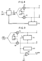
- Figure 8 is a block diagram of a demodulation stage employing the baseband estimator 19 of the invention.
- the source signal constituted by a signal at intermediate frequency IF or microwave SHF, is applied to the input of a transverse filter 90 operating at intermediate frequency or at microwave.
- the output signal of the filter 90 is a microwave corrected signal or at intermediate frequency .
- This corrected signal is applied to a demodulation stage comprising two mixers 91, 92 receiving demodulation signals in quadrature phase from a local oscillator 93.
- the output signals from the mixers 91, 92 constitute two demodulation components and corrected in baseband.
- the estimator of the invention can therefore also be used to generate a lean correction coefficient k p applied to a transverse filter not operating in baseband.
- FIG. 9 shows a demodulation stage where the baseband estimator of the invention is not used to provide a lean correction coefficient to a transverse filter.
- a source signal, SHF microwave or IF intermediate frequency, is demodulated using a demodulation stage comprising two mixers 94, 95 receiving two orthogonal phase signals from a local oscillator 96.
- the demodulation components I and Q supplied by these mixers 94, 95 are in baseband.
- a direct demodulation is carried out if the source signal is microwave SHF and if the local oscillator 96 supplies signals of orthogonal phases of frequency equal to the carrier frequency of the signal SHF.
- the uncorrected components I and Q are applied to the estimator 19 according to the invention which in particular generates the coefficient k p .
- the coefficient k p is supplied to display means 97 - possibly preceded by processing means - informing the user about the latch affecting the received SHF signal, and / or to a detector 98 generating a ALARM alarm signal if the value of k p becomes greater than a given REF reference value corresponding to a maximum tilt not to be exceeded.
- These uses of the estimator 19 are suitable for example for the development of transmitting / receiving stations in a telecommunications network by satellite or by terrestrial relay.
Landscapes
- Engineering & Computer Science (AREA)
- Computer Networks & Wireless Communication (AREA)
- Signal Processing (AREA)
- Digital Transmission Methods That Use Modulated Carrier Waves (AREA)
- Cable Transmission Systems, Equalization Of Radio And Reduction Of Echo (AREA)
- Filters That Use Time-Delay Elements (AREA)
- Superheterodyne Receivers (AREA)
Applications Claiming Priority (2)
| Application Number | Priority Date | Filing Date | Title |
|---|---|---|---|
| FR9315906 | 1993-12-30 | ||
| FR9315906A FR2714782B1 (fr) | 1993-12-30 | 1993-12-30 | Estimateur en bande de base de la caractéristique amplitude/fréquence d'un signal à pluralités de phases. |
Publications (2)
| Publication Number | Publication Date |
|---|---|
| EP0661833A1 true EP0661833A1 (de) | 1995-07-05 |
| EP0661833B1 EP0661833B1 (de) | 2001-12-19 |
Family
ID=9454602
Family Applications (1)
| Application Number | Title | Priority Date | Filing Date |
|---|---|---|---|
| EP94403031A Expired - Lifetime EP0661833B1 (de) | 1993-12-30 | 1994-12-27 | Basisband-Amplitude/Frequenz-Charakteristikschätzer |
Country Status (9)
| Country | Link |
|---|---|
| US (1) | US5677932A (de) |
| EP (1) | EP0661833B1 (de) |
| JP (1) | JPH07212426A (de) |
| AU (1) | AU687461B2 (de) |
| CA (1) | CA2139218A1 (de) |
| DE (1) | DE69429501T2 (de) |
| ES (1) | ES2167352T3 (de) |
| FR (1) | FR2714782B1 (de) |
| NZ (1) | NZ270098A (de) |
Cited By (1)
| Publication number | Priority date | Publication date | Assignee | Title |
|---|---|---|---|---|
| US11235112B2 (en) | 2012-02-29 | 2022-02-01 | Pulmatrix Operating Company, Inc. | Inhalable dry powders |
Families Citing this family (7)
| Publication number | Priority date | Publication date | Assignee | Title |
|---|---|---|---|---|
| EP0786887A1 (de) * | 1996-01-29 | 1997-07-30 | ALCATEL ITALIA S.p.A. | Verfahren zur Kompensierung von unterschiedlichen Gruppenlaufzeiten zwischen den analogen Filtern eines Quadratursenders oder -empfängers |
| DE19627788A1 (de) * | 1996-07-10 | 1998-01-15 | Bosch Gmbh Robert | Umschaltbare Frequenzweiche |
| US5963594A (en) * | 1996-12-31 | 1999-10-05 | Lucent Technologies Inc. | Vector tracking filter |
| US6377967B1 (en) * | 1998-08-12 | 2002-04-23 | Northrop Grumman Corporation | Efficient digital integration technique filter |
| US20030007583A1 (en) * | 2001-04-30 | 2003-01-09 | Hilton Howard E. | Correction of multiple transmission impairments |
| JP4563897B2 (ja) * | 2005-08-30 | 2010-10-13 | 日本放送協会 | マルチパス等化装置及びそれを備えた再送信装置 |
| JP4800026B2 (ja) * | 2005-12-16 | 2011-10-26 | 三星電子株式会社 | 複素係数トランスバーサルフィルタおよび周波数変換器 |
Family Cites Families (4)
| Publication number | Priority date | Publication date | Assignee | Title |
|---|---|---|---|---|
| US4020333A (en) * | 1975-05-06 | 1977-04-26 | International Business Machines Corporation | Digital filter for filtering complex signals |
| JPS59194540A (ja) * | 1983-04-19 | 1984-11-05 | Nec Corp | 自動適応型等化器 |
| DE3765947D1 (de) * | 1986-01-18 | 1990-12-13 | Hewlett Packard Ltd | Beeinflussungsfreier analysator zur erfassung von kanalstoerungen. |
| FR2706714B1 (fr) * | 1993-06-17 | 1995-07-21 | Alcatel Telspace | Système de réception d'un signal numérique à modulation de phase et d'amplitude. |
-
1993
- 1993-12-30 FR FR9315906A patent/FR2714782B1/fr not_active Expired - Fee Related
-
1994
- 1994-12-07 AU AU80302/94A patent/AU687461B2/en not_active Ceased
- 1994-12-08 NZ NZ270098A patent/NZ270098A/en unknown
- 1994-12-22 US US08/362,169 patent/US5677932A/en not_active Expired - Fee Related
- 1994-12-27 ES ES94403031T patent/ES2167352T3/es not_active Expired - Lifetime
- 1994-12-27 DE DE69429501T patent/DE69429501T2/de not_active Expired - Fee Related
- 1994-12-27 EP EP94403031A patent/EP0661833B1/de not_active Expired - Lifetime
- 1994-12-28 JP JP6328781A patent/JPH07212426A/ja active Pending
- 1994-12-28 CA CA002139218A patent/CA2139218A1/fr not_active Abandoned
Non-Patent Citations (2)
| Title |
|---|
| CHAMBERLAIN ET AL: "Receiver Techniques for Microwave Digital Radio", IEEE COMMUNICATIONS MAGAZINE, vol. 24, PISCATAWAY, NJ US, pages 43, XP000763557, DOI: doi:10.1109/MCOM.1986.1092974 * |
| DAVYRIAN: "Mobile Digital Communications via Tone Calibration", IEEE TRANSACTIONS ON VEHICULAR TECHNOLOGY, vol. VT-36, NEW YORK US, pages 55 * |
Cited By (1)
| Publication number | Priority date | Publication date | Assignee | Title |
|---|---|---|---|---|
| US11235112B2 (en) | 2012-02-29 | 2022-02-01 | Pulmatrix Operating Company, Inc. | Inhalable dry powders |
Also Published As
| Publication number | Publication date |
|---|---|
| AU8030294A (en) | 1995-07-06 |
| DE69429501T2 (de) | 2002-08-01 |
| US5677932A (en) | 1997-10-14 |
| ES2167352T3 (es) | 2002-05-16 |
| FR2714782B1 (fr) | 1996-02-02 |
| DE69429501D1 (de) | 2002-01-31 |
| NZ270098A (en) | 1996-12-20 |
| EP0661833B1 (de) | 2001-12-19 |
| CA2139218A1 (fr) | 1995-07-01 |
| JPH07212426A (ja) | 1995-08-11 |
| FR2714782A1 (fr) | 1995-07-07 |
| AU687461B2 (en) | 1998-02-26 |
Similar Documents
| Publication | Publication Date | Title |
|---|---|---|
| EP0421532B1 (de) | Vorverzerrungseinrichtung für digitale Übertragungssysteme | |
| EP0125722B1 (de) | Schaltungsanordnung zur kombinierten adaptativen Entzerrung und Demodulation | |
| EP0006121B1 (de) | Verfahren und Anordnung für die Startprozedur eines sich selbst einstellenden Entzerrers unter Bezugnahme auf ein unbekanntes Signal in einem, die Quadratur-Amplituden-Modulation verwendenden, Übertragungssystem | |
| US8041233B2 (en) | Adaptive equalization in coherent fiber optic communication | |
| EP2562945B1 (de) | Kurzfristige optische Wiederherstellungssysteme und Verfahren für kohärente optische Empfänger | |
| FR2837647A1 (fr) | Emetteur sans fil a consommation de puissance reduite | |
| JP2009253971A (ja) | デジタルコヒーレント光受信器において使用される周波数オフセット検出装置および検出方法 | |
| EP0329537A1 (de) | Übertragungssystem mit MSK-Modulation und kohärenter differentieller Detektion | |
| CA2201387A1 (fr) | Estimateur et recuperateur de phase robuste pour signaux numeriques affectes notamment de gigue de phase | |
| EP0661833B1 (de) | Basisband-Amplitude/Frequenz-Charakteristikschätzer | |
| EP0423666A1 (de) | Verfahren zur digitalen Korrektur der Nichtlinearität einer Sendekette und Anordnung zur Durchführung des Verfahrens | |
| CA2109880C (fr) | Dispositif de recuperation du rythme baud dans un recepteur pour modem | |
| EP0073869B1 (de) | Einrichtung zum Datenempfang mit einem hörerseitigen Echokompensator | |
| FR2479617A1 (fr) | Annuleur d'echo pour signal d'echo a phase variable | |
| EP2854354B1 (de) | Verfahren zur Bestimmung von Störstellen eines Sende- und eines Empfangswegs eines Geräts und dazugehörige Vorrichtung | |
| FR2755808A1 (fr) | Estimateur d'un defaut de fonctionnement d'un modulateur en quadrature et etage de modulation l'utilisant | |
| FR2758038A1 (fr) | Dispositif d'estimation de l'ecart de frequence existant entre la frequence porteuse d'un signal numerique et la frequence d'un oscillateur local de reception, et recepteur correspondant | |
| EP1235356B1 (de) | Empfänger für ein mobiles Funkkommunikationsendgerät | |
| EP1107528B1 (de) | Verfahren der Erkennung von Blöcken für einen schwindenden Kanal | |
| CA2057942C (fr) | Systeme recepteur pour le traitement de signaux recus sur des voies de diversite | |
| EP4099584B1 (de) | Abschwächung von entzerrungsverbessertem phasenrauschen in einem kohärenten optischen empfänger | |
| EP2976852B1 (de) | Taktrückgewinnungsvorrichtung | |
| EP1894322B1 (de) | Satellitenkommunikationssystem mit sendestationsdiversität | |
| FR3157997A1 (fr) | Procédé d'estimation d'un signal de retour souple dans un récepteur turbo basé sur la propagation d'espérance | |
| EP0026372A1 (de) | Schaltung zur Phasenregelung eines lokalen Oszillators für einen Empfänger von Datensignalen, welche mittels Einseitenband-Amplitudenmodulation übertragen werden |
Legal Events
| Date | Code | Title | Description |
|---|---|---|---|
| PUAI | Public reference made under article 153(3) epc to a published international application that has entered the european phase |
Free format text: ORIGINAL CODE: 0009012 |
|
| AK | Designated contracting states |
Kind code of ref document: A1 Designated state(s): DE ES FR GB IT NL SE |
|
| 17P | Request for examination filed |
Effective date: 19951223 |
|
| 17Q | First examination report despatched |
Effective date: 20000107 |
|
| GRAG | Despatch of communication of intention to grant |
Free format text: ORIGINAL CODE: EPIDOS AGRA |
|
| GRAG | Despatch of communication of intention to grant |
Free format text: ORIGINAL CODE: EPIDOS AGRA |
|
| GRAH | Despatch of communication of intention to grant a patent |
Free format text: ORIGINAL CODE: EPIDOS IGRA |
|
| GRAH | Despatch of communication of intention to grant a patent |
Free format text: ORIGINAL CODE: EPIDOS IGRA |
|
| GRAA | (expected) grant |
Free format text: ORIGINAL CODE: 0009210 |
|
| RAP1 | Party data changed (applicant data changed or rights of an application transferred) |
Owner name: ALCATEL |
|
| AK | Designated contracting states |
Kind code of ref document: B1 Designated state(s): DE ES FR GB IT NL SE |
|
| PG25 | Lapsed in a contracting state [announced via postgrant information from national office to epo] |
Ref country code: NL Free format text: LAPSE BECAUSE OF FAILURE TO SUBMIT A TRANSLATION OF THE DESCRIPTION OR TO PAY THE FEE WITHIN THE PRESCRIBED TIME-LIMIT Effective date: 20011219 |
|
| REG | Reference to a national code |
Ref country code: GB Ref legal event code: IF02 |
|
| PGFP | Annual fee paid to national office [announced via postgrant information from national office to epo] |
Ref country code: GB Payment date: 20020115 Year of fee payment: 8 |
|
| PGFP | Annual fee paid to national office [announced via postgrant information from national office to epo] |
Ref country code: DE Payment date: 20020117 Year of fee payment: 8 |
|
| PGFP | Annual fee paid to national office [announced via postgrant information from national office to epo] |
Ref country code: FR Payment date: 20020118 Year of fee payment: 8 |
|
| GBT | Gb: translation of ep patent filed (gb section 77(6)(a)/1977) |
Effective date: 20020102 |
|
| PGFP | Annual fee paid to national office [announced via postgrant information from national office to epo] |
Ref country code: ES Payment date: 20020130 Year of fee payment: 8 |
|
| REF | Corresponds to: |
Ref document number: 69429501 Country of ref document: DE Date of ref document: 20020131 |
|
| PG25 | Lapsed in a contracting state [announced via postgrant information from national office to epo] |
Ref country code: SE Free format text: LAPSE BECAUSE OF FAILURE TO SUBMIT A TRANSLATION OF THE DESCRIPTION OR TO PAY THE FEE WITHIN THE PRESCRIBED TIME-LIMIT Effective date: 20020319 |
|
| REG | Reference to a national code |
Ref country code: ES Ref legal event code: FG2A Ref document number: 2167352 Country of ref document: ES Kind code of ref document: T3 |
|
| NLV1 | Nl: lapsed or annulled due to failure to fulfill the requirements of art. 29p and 29m of the patents act | ||
| PLBE | No opposition filed within time limit |
Free format text: ORIGINAL CODE: 0009261 |
|
| STAA | Information on the status of an ep patent application or granted ep patent |
Free format text: STATUS: NO OPPOSITION FILED WITHIN TIME LIMIT |
|
| 26N | No opposition filed | ||
| PG25 | Lapsed in a contracting state [announced via postgrant information from national office to epo] |
Ref country code: GB Free format text: LAPSE BECAUSE OF NON-PAYMENT OF DUE FEES Effective date: 20021227 |
|
| PG25 | Lapsed in a contracting state [announced via postgrant information from national office to epo] |
Ref country code: ES Free format text: LAPSE BECAUSE OF NON-PAYMENT OF DUE FEES Effective date: 20021228 |
|
| NLV1 | Nl: lapsed or annulled due to failure to fulfill the requirements of art. 29p and 29m of the patents act | ||
| PG25 | Lapsed in a contracting state [announced via postgrant information from national office to epo] |
Ref country code: DE Free format text: LAPSE BECAUSE OF NON-PAYMENT OF DUE FEES Effective date: 20030701 |
|
| GBPC | Gb: european patent ceased through non-payment of renewal fee |
Effective date: 20021227 |
|
| PG25 | Lapsed in a contracting state [announced via postgrant information from national office to epo] |
Ref country code: FR Free format text: LAPSE BECAUSE OF NON-PAYMENT OF DUE FEES Effective date: 20030901 |
|
| REG | Reference to a national code |
Ref country code: FR Ref legal event code: ST |
|
| REG | Reference to a national code |
Ref country code: ES Ref legal event code: FD2A Effective date: 20021228 |
|
| PG25 | Lapsed in a contracting state [announced via postgrant information from national office to epo] |
Ref country code: IT Free format text: LAPSE BECAUSE OF NON-PAYMENT OF DUE FEES;WARNING: LAPSES OF ITALIAN PATENTS WITH EFFECTIVE DATE BEFORE 2007 MAY HAVE OCCURRED AT ANY TIME BEFORE 2007. THE CORRECT EFFECTIVE DATE MAY BE DIFFERENT FROM THE ONE RECORDED. Effective date: 20051227 |