EP0421532B1 - Vorverzerrungseinrichtung für digitale Übertragungssysteme - Google Patents
Vorverzerrungseinrichtung für digitale Übertragungssysteme Download PDFInfo
- Publication number
- EP0421532B1 EP0421532B1 EP90202588A EP90202588A EP0421532B1 EP 0421532 B1 EP0421532 B1 EP 0421532B1 EP 90202588 A EP90202588 A EP 90202588A EP 90202588 A EP90202588 A EP 90202588A EP 0421532 B1 EP0421532 B1 EP 0421532B1
- Authority
- EP
- European Patent Office
- Prior art keywords
- bits
- data
- arrangement
- circuit
- predistortion
- Prior art date
- Legal status (The legal status is an assumption and is not a legal conclusion. Google has not performed a legal analysis and makes no representation as to the accuracy of the status listed.)
- Expired - Lifetime
Links
Images



Classifications
-
- H—ELECTRICITY
- H03—ELECTRONIC CIRCUITRY
- H03F—AMPLIFIERS
- H03F1/00—Details of amplifiers with only discharge tubes, only semiconductor devices or only unspecified devices as amplifying elements
- H03F1/32—Modifications of amplifiers to reduce non-linear distortion
- H03F1/3241—Modifications of amplifiers to reduce non-linear distortion using predistortion circuits
- H03F1/3247—Modifications of amplifiers to reduce non-linear distortion using predistortion circuits using feedback acting on predistortion circuits
-
- H—ELECTRICITY
- H04—ELECTRIC COMMUNICATION TECHNIQUE
- H04B—TRANSMISSION
- H04B1/00—Details of transmission systems, not covered by a single one of groups H04B3/00 - H04B13/00; Details of transmission systems not characterised by the medium used for transmission
- H04B1/62—Details of transmission systems, not covered by a single one of groups H04B3/00 - H04B13/00; Details of transmission systems not characterised by the medium used for transmission for providing a predistortion of the signal in the transmitter and corresponding correction in the receiver, e.g. for improving the signal/noise ratio
-
- H—ELECTRICITY
- H04—ELECTRIC COMMUNICATION TECHNIQUE
- H04L—TRANSMISSION OF DIGITAL INFORMATION, e.g. TELEGRAPHIC COMMUNICATION
- H04L27/00—Modulated-carrier systems
- H04L27/32—Carrier systems characterised by combinations of two or more of the types covered by groups H04L27/02, H04L27/10, H04L27/18 or H04L27/26
- H04L27/34—Amplitude- and phase-modulated carrier systems, e.g. quadrature-amplitude modulated carrier systems
- H04L27/36—Modulator circuits; Transmitter circuits
- H04L27/366—Arrangements for compensating undesirable properties of the transmission path between the modulator and the demodulator
- H04L27/367—Arrangements for compensating undesirable properties of the transmission path between the modulator and the demodulator using predistortion
- H04L27/368—Arrangements for compensating undesirable properties of the transmission path between the modulator and the demodulator using predistortion adaptive predistortion
-
- H—ELECTRICITY
- H03—ELECTRONIC CIRCUITRY
- H03F—AMPLIFIERS
- H03F2200/00—Indexing scheme relating to amplifiers
- H03F2200/438—Separate feedback of amplitude and phase signals being present
-
- H—ELECTRICITY
- H03—ELECTRONIC CIRCUITRY
- H03F—AMPLIFIERS
- H03F2200/00—Indexing scheme relating to amplifiers
- H03F2200/57—Separate feedback of real and complex signals being present
Definitions
- the invention relates to a predistortion device for a digital transmission system which transmits complex input data at the rate of a symbol clock H of period T, using a modulator and a power amplifier which distorts the data, the device comprising a predistortion circuit which predistorts in the opposite direction the input data before it passes through the amplifier in order to transmit the expected input data.
- the invention finds its applications in digital transmission systems such as data transmission modems, radio-relay systems, space communications systems.
- the level of the signal transmitted is fixed so as to establish a compromise between the signal to noise ratio and the non-linear distortion undergone by the signal.
- the optimum operating point of the amplifier is that minimizing the joint effects of the additive noise of the channel and the non-linear distortion of the amplifier.
- this point is far from the saturation power of the amplifier, which means that it is not used effectively.
- predistortion techniques fixed or adaptive are commonly used which make it possible to reduce the effect of the non-linearity of the power amplifier on the transmitted signal.
- a commonly used predistortion technique consists in placing on the intermediate frequency stage of the transmitter a non-linear circuit approaching the inverse function of the power amplifier whose non-linearities are aimed at compensating for. If we knew how to synthesize the exact inverse of the amplifier function, this technique would allow a perfect signal to be output (without any non-linear distortion). However, this is not feasible, because the exact opposite would require a circuit of infinite complexity. In practice, we just make an approximation and most often we limit to order 3 the Taylor series representing the non-linear function of the amplifier and we synthesize a predistortion circuit, also of order 3, such that the two cascaded circuits no longer have order 3 distortion.
- Another, more recent predistortion technique consists in modifying the alphabet of the data to be transmitted.
- This technique called “data predistortion” or “baseband predistortion” is known from document US-A-4,291,277 and from the article by A.A.M. SALEH and J. SALZ "Adaptive linearization of power amplifiers in digital radio systems" Bell System Technical Journal Vol. 62 April 1983, pages 1019-1033.
- FIG. 1 is a diagram of an adaptive predistortion circuit which supplies at the input of the modulator a distorted constellation starting from the original square constellation, for example of amplitude modulation of two carriers in quadrature MAQ.
- the amplifier acts on the constellation by producing a clear compression and a clear rotation of the points of great amplitude. To compensate for this effect, the original constellation is distorted so that it returns to its original square shape after passing through the power amplifier.
- the predistortion circuit when the predistortion circuit is optimized, it forms the inverse of the power amplifier (to a gain and to a phase) and makes it possible to perfectly compensate for the non-linearities of the amplifier.
- the signal is taken up at the output of the amplifier, demodulated, then sampled at the transmission rate of the symbols 1 / T and these samples are compared at the corresponding point of the MAQ constellation used.
- These comparisons make it possible to obtain a control signal making it possible to optimize the predistortion circuit using a conventional algorithm.
- the diagram used in this figure 1 is very simplistic, because it has no filtering before the modulator, nor before the power amplifier. It therefore does not correspond to the solution generally used.
- Nyquist type spectral shaping filtering to limit the signal band while guaranteeing zero intersymbol interference at decision times.
- This filtering is generally shared equitably between transmission and reception to maximize the signal-to-noise ratio also at decision times.
- the effect of the amplifier's non-linearity is twofold: the constellation is not only distorted, but an intersymbol interference appears which associates with each point of the constellation a cloud of points.
- the predistortion technique described above does not make it possible to compensate for this second effect.
- the problem posed is therefore to produce a predistortion circuit which makes it possible not only to correct the constellation but also to considerably reduce the dispersion of each point of the original constellation into a cloud of points and also to provide protection on reception. high against interference from adjacent channels.
- the system includes an emission filter which, from the input data, delivers, at the rate k / T (where k is an integer greater than 1), filtered oversampled data.
- the predistortion circuit which comprises means for firstly determining approximate predistorted data (F Io , F Qo ) from a 2 M bits part of the fields of the 2 N bits (M ⁇ N), data which are then revised using the remaining part of the 2 (NM) bit fields to provide revised predistorted input data (F ⁇ I , F ⁇ Q ).
- the emission filter performs spectral shaping which is supplemented by reception filtering so that the global emission-reception filtering is a Nyquist filter thus making it possible to guarantee zero intersymbol interference at the decision times.
- reception filtering is a Nyquist filter
- the cascade determination of the predistorted data approached and then of the revised data requires only a reduced hardware, compared to a determination using complete fields of 2 N bits.
- This is particularly sensitive when the predistortion circuit uses a memory.
- the predistortion circuit comprises for each channel a separator of the field of M bits and the field of (NM) bits, a memory addressed by the field of 2 M bits which delivers the approximate predistorted data (F Io , F Qo ) , and an interpolation circuit which deduces the predistorted data (F ⁇ I , F ⁇ Q ).
- the interpolation circuit will use the approximate predistorted data (F Io , F Qo ) to which it will add values which depend on the processing mechanism implemented by the separation 2 M bit fields and 2 (NM) bit fields.
- a simple way of carrying out this separation consists in isolating for each channel the M most significant bits from the (NM) least significant bits.
- the field of M bits represents a value x
- the field of (NM) bits represents a value ⁇ x (respectively y and ⁇ y for the other channel).
- the interpolation circuit can perform a linear approximation around the point (F Io , F Qo ).
- the values ⁇ x and ⁇ y correspond to a deviation of 1 least significant bit from the corresponding address bit field.
- the predistortion circuit is adaptive and for this includes an adaptation circuit which, from a demodulation of the stream of transmitted data, continuously adapts the predistortion circuit from a comparison of the input data and the data transmitted. The observed difference is used to correct the predistorted values (F Io , F Qo ) which are stored in memory and which are regularly updated.
- the emission filter placed at the input of the system and which delivers several samples per symbol duration can consist of a digital filter. It can also consist of an analog filter followed by an analog to digital converter which delivers samples at the same rates.
- Figure 1 the constellation of a MAQ64 modulation.
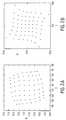
- FIG. 2A a MAQ64 constellation distorted by the power amplifier in a system without filtering or in the case where all of the Nyquist filtering is carried out after the amplifier stage.
- FIG. 2B a predistorted constellation optimized to compensate for the distortion illustrated in FIG. 2A according to the prior art.
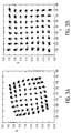
- FIG. 3A the constellation distorted by the amplifier as it appears when the global filtering is equitably shared between transmission and reception and the part on transmission is placed before the amplifier.
- Figure 3B with the same situation as that of Figure 3A, but incorporating the predistortion circuit of the prior art.
- Figure 4 a diagram of a digital transmission system according to the invention.
- FIG. 5 a diagram of a predistortion circuit according to the invention.
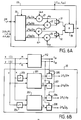
- FIGS. 6A, 6B an exemplary embodiment of the predistortion circuit.
- FIG. 7 a diagram of a digital transmission system provided with an adaptive predistortion circuit according to the invention.
- FIG. 1 is a reminder of the representation of the constellation of a signal of MAQ64 type.
- the inputs I (in phase) and Q (in quadrature) of the modulator are independent and the symbols on each channel take their values in a alphabet ( ⁇ d, ⁇ 3d, ⁇ 5d, ⁇ 7d).
- the signal from the modulator is introduced into a power amplifier which is generally used at reduced power, that is to say in a linear part of its characteristic. At high power this amplifier is non-linear and distorts the signal unacceptably. If a MAQ64 type constellation is observed at the output of such an amplifier operating close to saturation, a distorted constellation like that shown in FIG. 2A is observed. According to the prior art, it then suffices to predistort the constellation in the opposite direction according to the diagram in FIG. 2B so that at the output of the amplifier the original constellation is not deformed. However, such a simple situation does not conform to reality where there is always a filtering before the power amplifier in particular to limit the signal band.
- the signal at the input of the modulator varies in stages once per symbol duration T.
- a predistortion circuit acting on the signal at rate 1 / T allows perfect compensation.
- the signal when the signal is filtered, it no longer varies in stages but in a continuous manner. For perfect compensation for the effect of non-linearity, it is no longer sufficient to observe the signal once per symbol duration T and to compensate for the distortion at these times.
- the constellation at the output of the amplifier is shown in Figure 3A. It becomes as shown in FIG. 3B with the predistortion circuit of the prior art. Thus each point of the constellation becomes a cloud of points which is unacceptable. To operate with a filtered signal it is therefore necessary to operate the correction at more than one point per symbol duration.
- the emission spectral shaping is carried out by a digital filter delivering at its output the filtered data at the rate k / T (k ⁇ 2).
- this shaping is carried out by an analog filter, the signal leaving the filter is sampled at the rate k / T. We thus have all the T / k of the samples of the filtered signal which can be predistorted.
- FIG. 4 represents a digital transmission system with a predistortion device 9 provided with a transmission filter 10 which delivers samples, coded on N bits, at the rate k / T (k integer at least equal to 2), and a predistortion circuit 11 followed by a digital-analog converter 12, an analog filter 13, a modulator 14 and the amplifier 15. It is this amplifier which distorts the data which it has to transmit to the transmitting antenna.
- a predistortion device 9 provided with a transmission filter 10 which delivers samples, coded on N bits, at the rate k / T (k integer at least equal to 2), and a predistortion circuit 11 followed by a digital-analog converter 12, an analog filter 13, a modulator 14 and the amplifier 15. It is this amplifier which distorts the data which it has to transmit to the transmitting antenna.
- FIG. 5 represents an example of a diagram of the predistortion circuit 11. It includes a separator 110 which receives the complex data coded on 2 N bits (channels I and Q) and which separates for each channel a field of M weight bits strong and a remaining field of (NM) least significant bits (M ⁇ N).
- the 2 M bit fields address a memory 112 which stores approximate predistorted values (F Io , F Qo ).
- the 2 (NM) bit fields enter an interpolation circuit 111.
- the two (NM) bit fields respectively represent a value ⁇ x and ⁇ y for each channel.
- the two M-bit fields respectively represent an x and y value for each channel.
- the interpolation circuit 111 From the approximate data F Io , F Qo and their address fields, the interpolation circuit 111 will calculate, using the values ⁇ x, ⁇ y, the revised data (F ⁇ I , F ⁇ Q.
- a circuit 20 for calculating partial derivatives calculates the partial derivatives by applying increments ⁇ x, ⁇ y to the values associated with the address fields. These derivatives partial values and the values ⁇ x, ⁇ y are used to determine F ⁇ I , F ⁇ Q according to the preceding equations using multipliers 21, 22, 23, 24 and adders 31, 32, 33.
- the circuit 20 can contain the memory 112. In this case this memory is read several times successively to operate according to the mechanism described below. But preferably three memories are used in order to operate processing in parallel according to the diagram in FIG. 6B.
- Two memories 201, 202 store the same data as memory 112.
- Memory 201 is addressed by the field Q of M bits and by the field I of M bits (value x) which is incremented by 1 bit in the adder 203. This value of 1 bit (increment ⁇ x) makes it possible to calculate the partial derivatives ⁇ F I / ⁇ x, ⁇ F Q / ⁇ x by simple difference in the subtractors 205 and 207 for channels I and Q.
- the memory 202 is addressed by the field I of M bits and by the field Q of M bits (value y) which is incremented by 1 bit in the adder 204.
- This value of 1 bit (increment ⁇ y) makes it possible to calculate the partial derivatives ⁇ F I / ⁇ y and ⁇ F Q / ⁇ y by simple difference in the subtractors 206 and 208 for the channels I and Q.
- N is generally of the order of 10 bits.
- the emission filter 10 (FIG. 4) must deliver the complex samples coded on N bits at the rate k / T with k at least equal to 2.
- This emission filter can be a digital filter. It can also consist of an analog filter followed by an analog-digital conversion.
- the diagram in FIG. 4 represents a transmission system which makes it possible to predistort the data and to correct the distortions provided by the amplifier in the case of a fixed structure. But it is also possible to produce an adaptive structure.
- This is shown in the diagram in Figure 7.
- the output signal from the amplifier 15 is taken to introduce it into a demodulator 81 followed by a low-pass filter 82, the output of which enters an adaptation circuit 83.
- the latter samples the signal filter 82 output and compare this data to the input data. The difference gives rise to an error signal which makes it possible (connection 84) to update the predistortion circuit 11 for example by storing new values F Io , F Qo in the memory.
Landscapes
- Engineering & Computer Science (AREA)
- Computer Networks & Wireless Communication (AREA)
- Signal Processing (AREA)
- Physics & Mathematics (AREA)
- Nonlinear Science (AREA)
- Power Engineering (AREA)
- Cable Transmission Systems, Equalization Of Radio And Reduction Of Echo (AREA)
- Digital Transmission Methods That Use Modulated Carrier Waves (AREA)
- Dc Digital Transmission (AREA)
- Amplifiers (AREA)
- Transmitters (AREA)
Claims (9)
- Vorverzerrungseinrichtung (9) für ein digitales Übertragungssystem, das komplexe Eingangsdaten einer Konfiguration im Zyklus eines Zeichentaktgebers H der Periode T mittels eines Modulators (14) und eines Leistungsverstärkers (15), der die Daten verzerrt, überträgt, wobei die Einrichtung eine Vorverzerrungsschaltung (11) umfaßt, die die Eingangsdaten in entgegengesetzter Richtung vor ihrem Eintritt in den Verstärker vorverzerrt, um die erwarteten Eingangsdaten zu übertragen, dadurch gekennzeichnet, daß sie einen Sendefilter (10) umfaßt, der aus den Eingangsdaten im Takt k/T (mit k = ganzzahlig größer 1) gefilterte, überabgetastete, auf 2 N Bits codierte Daten an die Vorverzerrungsschaltung (11) ausgibt, die Mittel (110, 111, 112) umfaßt, um zuerst vorverzerrte Näherungswerte (FIo, FQo) aus einem 2 M Bit-Teil des 2 N Bit-Felds (M < N) zu bestimmen, um diese Daten mit Hilfe des übrigen Teils des 2 (N-M) Bit-Felds zu korrigieren und um korrigierte vorverzerrte Eingangsdaten (FI, FQ) auszugeben.
- Einrichtung nach Anspruch 1, dadurch gekennzeichnet, daß die Vorverzerrungsschaltung für jede Strecke eine Einrichtung (110) zum Auftrennen des M Bit-Felds und des (N-M) Bit-Felds, einen vom M Bit-Feld adressierten Speicher (112), der vorverzerrte Näherungswerte (FIo, FQo) ausgibt, und eine Interpolationsschaltung (111), die daraus die vorverzerrten korrigierten Daten (FI, FQ) ableitet, umfaßt.
- Einrichtung nach Anspruch 2, dadurch gekennzeichnet, daß die Interpolationsschaltung (111) eine lineare Näherung an die Punkte (FIo, FQo) durchführt.
- Einrichtung nach Anspruch 3, dadurch gekennzeichnet, daß die Einrichtung zum Auftrennen (110) die Felder der höherwertigen M Bits abtrennt, wobei die Interpolationsschaltung (111) die Daten F̂I, F̂Q nach folgender Gleichung bestimmt:


- Einrichtung nach Anspruch 4, dadurch gekennzeichnet, daß man die Werte ∂FI/∂x und ∂FQ/∂x einerseits und ∂FI/∂y und ∂FQ/∂y andererseits erhält, indem der Speicher (112) nacheinander durch die Werte [(x+∂x);y] und [x;(y+∂y)] adressiert wird.
- Einrichtung nach Anspruch 5, dadurch gekennzeichnet, daß der Inhalt des Speichers (112) in zwei andere Speicher dupliziert wird, um eine Parallelberechnung der partiellen Ableitungen zu ermöglichen.
- Einrichtung nach einem der Ansprüche 4 bis 6, dadurch gekennzeichnet, daß die Werte von ∂x und ∂y einem Abstand von 1 niederwertigeren Bit des entsprechenden Adreßbitfelds entsprechen.
- Einrichtung nach einem der Ansprüche 1 bis 7, dadurch gekennzeichnet, daß der Sendefilter (10) entweder ein digitaler oder ein analoger Filter mit nachgeschaltetem Analog-Digital-Umsetzer ist.
- Einrichtung nach einem der Ansprüche 1 bis 8, dadurch gekennzeichnet, daß die Vorverzerrungsschaltung (11) adaptiv ist und hierzu eine Anpassungsschaltung (83) umfaßt, die anhand einer Demodulation des übertragenen Datenstroms die Vorverzerrungsschaltung (11) anhand eines Vergleichs der Eingangsdaten und der übertragenen Daten kontinuierlich anpaßt.
Applications Claiming Priority (2)
| Application Number | Priority Date | Filing Date | Title |
|---|---|---|---|
| FR8913093 | 1989-10-06 | ||
| FR8913093A FR2652965A1 (fr) | 1989-10-06 | 1989-10-06 | Dispositif de predistorsion pour systeme de transmission numerique. |
Publications (2)
| Publication Number | Publication Date |
|---|---|
| EP0421532A1 EP0421532A1 (de) | 1991-04-10 |
| EP0421532B1 true EP0421532B1 (de) | 1995-01-11 |
Family
ID=9386166
Family Applications (1)
| Application Number | Title | Priority Date | Filing Date |
|---|---|---|---|
| EP90202588A Expired - Lifetime EP0421532B1 (de) | 1989-10-06 | 1990-10-01 | Vorverzerrungseinrichtung für digitale Übertragungssysteme |
Country Status (7)
| Country | Link |
|---|---|
| US (1) | US5105445A (de) |
| EP (1) | EP0421532B1 (de) |
| JP (1) | JP3076593B2 (de) |
| AU (1) | AU641874B2 (de) |
| CA (1) | CA2026819A1 (de) |
| DE (1) | DE69015944T2 (de) |
| FR (1) | FR2652965A1 (de) |
Families Citing this family (53)
| Publication number | Priority date | Publication date | Assignee | Title |
|---|---|---|---|---|
| FR2644638B1 (de) * | 1989-03-14 | 1991-05-31 | Labo Electronique Physique | |
| US5177769A (en) * | 1991-05-03 | 1993-01-05 | Bell Communications Research, Inc. | Digital circuits for generating signal sequences for linear TDMA systems |
| SE468616B (sv) * | 1991-06-12 | 1993-02-15 | Ericsson Telefon Ab L M | Foerfarande foer kompensering av saendarnyttosignalens beroende av oeverfoeringsfunktionen foer ett combinerfilter |
| US5295138A (en) * | 1992-04-21 | 1994-03-15 | Northwest Starscon Limited Partnership | Apparatus and method for optimal frequency planning in frequency division multiplexing transmissions |
| FR2692092B1 (fr) * | 1992-06-05 | 1994-07-22 | Thomson Csf | Dispositif de traitement et de precorrection d'un signal audiofrequence avant son amplification dans une chaine d'amplification d'un emetteur a modulation d'amplitude. |
| JP3166321B2 (ja) * | 1992-07-01 | 2001-05-14 | 日本電気株式会社 | 変調信号送信システム |
| US5351016A (en) * | 1993-05-28 | 1994-09-27 | Ericsson Ge Mobile Communications Inc. | Adaptively self-correcting modulation system and method |
| DE69310775T2 (de) * | 1993-07-09 | 1997-11-13 | Edmunde Eugene Newhall | Systeme mit erhöhter geschwindigkeit der informationsübertragung, welche eingebettete abtastmodulation und vorverzerrungsausgleich verwenden |
| US5612991A (en) * | 1995-03-31 | 1997-03-18 | Intel Corporation | Use of RSSI indication for improved data transmission over amps network |
| FR2739239B1 (fr) * | 1995-09-27 | 1997-11-14 | Alcatel Telspace | Dispositif de correction d'un defaut de quadrature d'un modulateur en quadrature et/ou d'un demodulateur d'un signal a pluralite d'etats de phase, emetteur et recepteur correspondants |
| US5881376A (en) * | 1995-12-15 | 1999-03-09 | Telefonaktiebolaget Lm Ericsson | Digital calibration of a transceiver |
| US5661758A (en) * | 1996-01-16 | 1997-08-26 | Long; Michael E. | Single cycle data encoding method and apparatus |
| AU739051B2 (en) * | 1996-12-24 | 2001-10-04 | General Dynamics Government Systems Corporation | Symbol lock detector |
| US5987069A (en) * | 1996-12-24 | 1999-11-16 | Gte Government Systems Corporation | Method and apparatus for variably allocating upstream and downstream communication spectra |
| KR100251561B1 (ko) | 1997-06-19 | 2000-04-15 | 윤종용 | 디지털통신시스템의송신기선형화장치및방법 |
| US6081158A (en) * | 1997-06-30 | 2000-06-27 | Harris Corporation | Adaptive pre-distortion apparatus for linearizing an amplifier output within a data transmission system |
| US6112062A (en) * | 1997-09-26 | 2000-08-29 | The Whitaker Corporation | Predistortion for high power amplifiers |
| JP2000013247A (ja) * | 1998-06-18 | 2000-01-14 | Nec Corp | 送信電力制御回路 |
| US6304594B1 (en) | 1998-07-27 | 2001-10-16 | General Dynamics Government Systems Corporation | Interference detection and avoidance technique |
| US6191653B1 (en) | 1998-11-18 | 2001-02-20 | Ericsson Inc. | Circuit and method for linearizing amplitude modulation in a power amplifier |
| US6194963B1 (en) | 1998-11-18 | 2001-02-27 | Ericsson Inc. | Circuit and method for I/Q modulation with independent, high efficiency amplitude modulation |
| US6295442B1 (en) | 1998-12-07 | 2001-09-25 | Ericsson Inc. | Amplitude modulation to phase modulation cancellation method in an RF amplifier |
| US6212229B1 (en) | 1998-12-16 | 2001-04-03 | General Dynamics Government Systems Corporation | Adaptive pre-emphasis technique |
| US6493400B1 (en) | 1999-04-19 | 2002-12-10 | Bae Systems Aerospace Electronics Inc. | Harmonic cancellation system |
| US6473133B1 (en) * | 1999-05-14 | 2002-10-29 | Harris Corporation | Broadcast transmission system with correction for distortion caused by amplifying and signal conditioning components at a different rate |
| FR2824437B1 (fr) * | 2001-05-04 | 2005-06-03 | Eads Defence & Security Ntwk | Generateur d'un signal radiofrequence module en phase ou frequence et en amplitude, et emetteur l'incorporant |
| US6700439B2 (en) | 2002-04-11 | 2004-03-02 | Andrew Corporation | Zero-bias bypass switch |
| US6812786B2 (en) * | 2002-04-11 | 2004-11-02 | Andrew Corporation | Zero-bias bypass switching circuit using mismatched 90 degrees hybrid |
| US8811917B2 (en) | 2002-05-01 | 2014-08-19 | Dali Systems Co. Ltd. | Digital hybrid mode power amplifier system |
| US6985704B2 (en) | 2002-05-01 | 2006-01-10 | Dali Yang | System and method for digital memorized predistortion for wireless communication |
| US8472897B1 (en) | 2006-12-22 | 2013-06-25 | Dali Systems Co. Ltd. | Power amplifier predistortion methods and apparatus |
| US8380143B2 (en) | 2002-05-01 | 2013-02-19 | Dali Systems Co. Ltd | Power amplifier time-delay invariant predistortion methods and apparatus |
| JP2004032609A (ja) * | 2002-06-28 | 2004-01-29 | Nec Corp | 非線形歪み補償回路 |
| US6801582B2 (en) * | 2002-09-13 | 2004-10-05 | Allied Telesyn, Inc. | Apparatus and method for improving an output signal from a nonlinear device through dynamic signal pre-distortion based upon Lagrange interpolation |
| US7469491B2 (en) | 2004-01-27 | 2008-12-30 | Crestcom, Inc. | Transmitter predistortion circuit and method therefor |
| US7099399B2 (en) * | 2004-01-27 | 2006-08-29 | Crestcom, Inc. | Distortion-managed digital RF communications transmitter and method therefor |
| US7430248B2 (en) * | 2004-01-27 | 2008-09-30 | Crestcom, Inc. | Predistortion circuit and method for compensating nonlinear distortion in a digital RF communications transmitter |
| US20050163249A1 (en) * | 2004-01-27 | 2005-07-28 | Crestcom, Inc. | Predistortion circuit and method for compensating linear distortion in a digital RF communications transmitter |
| US20060104385A1 (en) * | 2004-11-15 | 2006-05-18 | Newhall Edmunde E | Systems with increased information rates using embedded sample modulation and predistortion equalization implemented on metallic lines |
| US7586428B2 (en) * | 2005-02-25 | 2009-09-08 | Telefonaktiebolaget L M Ericsson (Publ) | Non-linear processing of signals |
| US20070082617A1 (en) * | 2005-10-11 | 2007-04-12 | Crestcom, Inc. | Transceiver with isolation-filter compensation and method therefor |
| CN101479956B (zh) | 2006-04-28 | 2013-07-31 | 大力系统有限公司 | 用于无线通信的高效率线性化功率放大器 |
| US20080134394P1 (en) * | 2006-12-01 | 2008-06-05 | Syngenta Seeds B.V. | Geranium plant named 'Zonadared' |
| US7724840B2 (en) * | 2006-12-19 | 2010-05-25 | Crestcom, Inc. | RF transmitter with predistortion and method therefor |
| CN104202279A (zh) | 2006-12-26 | 2014-12-10 | 大力系统有限公司 | 用于多信道宽带通信系统中的基带预失真线性化的方法和系统 |
| US20080285640A1 (en) * | 2007-05-15 | 2008-11-20 | Crestcom, Inc. | RF Transmitter With Nonlinear Predistortion and Method Therefor |
| CN105141513B (zh) | 2010-09-14 | 2018-12-14 | 大力系统有限公司 | 操作分布式天线系统的方法和在该系统中进行通信的方法 |
| US9088319B2 (en) * | 2011-04-21 | 2015-07-21 | Mediatek Singapore Pte. Ltd. | RF transmitter architecture, integrated circuit device, wireless communication unit and method therefor |
| US10129055B2 (en) | 2011-04-21 | 2018-11-13 | Mediatek Singapore Pte. Ltd. | PA cell, PA module, wireless communication unit, RF transmitter architecture and method therefor |
| US9379742B2 (en) | 2011-04-21 | 2016-06-28 | Mediatek Singapore Pte. Ltd. | RF transmitter, integrated circuit device, wireless communication unit and method therefor |
| US9559879B2 (en) | 2011-04-21 | 2017-01-31 | Mediatek Singapore Pte. Ltd. | PA cell, PA module, wireless communication unit, RF transmitter architecture and method therefor |
| US9647866B2 (en) | 2011-04-21 | 2017-05-09 | Mediatek Singapore Pte, Ltd. | RF transmitter, integrated circuit device, wireless communication unit and method therefor |
| JP6286908B2 (ja) * | 2013-07-19 | 2018-03-07 | 住友電気工業株式会社 | 増幅装置及び無線通信装置 |
Family Cites Families (8)
| Publication number | Priority date | Publication date | Assignee | Title |
|---|---|---|---|---|
| US4291277A (en) * | 1979-05-16 | 1981-09-22 | Harris Corporation | Adaptive predistortion technique for linearizing a power amplifier for digital data systems |
| US4462001A (en) * | 1982-02-22 | 1984-07-24 | Canadian Patents & Development Limited | Baseband linearizer for wideband, high power, nonlinear amplifiers |
| US4554514A (en) * | 1984-12-21 | 1985-11-19 | Rca Corporation | Predistortion circuit with feedback |
| US4700151A (en) * | 1985-03-20 | 1987-10-13 | Nec Corporation | Modulation system capable of improving a transmission system |
| US4675618A (en) * | 1986-06-09 | 1987-06-23 | Rockwell International Corporation | Linearizer circuit for frequency modulation oscillator |
| FR2642243B1 (fr) * | 1989-01-24 | 1991-04-19 | Labo Electronique Physique | Circuit de predistorsion adaptative |
| FR2644638B1 (de) * | 1989-03-14 | 1991-05-31 | Labo Electronique Physique | |
| FR2652969A1 (fr) * | 1989-10-06 | 1991-04-12 | Philips Electronique Lab | Dispositif de predistorsion pour systeme de transmission numerique. |
-
1989
- 1989-10-06 FR FR8913093A patent/FR2652965A1/fr not_active Withdrawn
-
1990
- 1990-10-01 EP EP90202588A patent/EP0421532B1/de not_active Expired - Lifetime
- 1990-10-01 DE DE69015944T patent/DE69015944T2/de not_active Expired - Fee Related
- 1990-10-03 JP JP02266162A patent/JP3076593B2/ja not_active Expired - Fee Related
- 1990-10-03 CA CA002026819A patent/CA2026819A1/en not_active Abandoned
- 1990-10-04 AU AU63747/90A patent/AU641874B2/en not_active Ceased
- 1990-10-09 US US07/595,120 patent/US5105445A/en not_active Expired - Lifetime
Also Published As
| Publication number | Publication date |
|---|---|
| FR2652965A1 (fr) | 1991-04-12 |
| JPH03135249A (ja) | 1991-06-10 |
| DE69015944T2 (de) | 1995-08-24 |
| DE69015944D1 (de) | 1995-02-23 |
| CA2026819A1 (en) | 1991-04-07 |
| US5105445A (en) | 1992-04-14 |
| JP3076593B2 (ja) | 2000-08-14 |
| EP0421532A1 (de) | 1991-04-10 |
| AU6374790A (en) | 1991-04-11 |
| AU641874B2 (en) | 1993-09-30 |
Similar Documents
| Publication | Publication Date | Title |
|---|---|---|
| EP0421532B1 (de) | Vorverzerrungseinrichtung für digitale Übertragungssysteme | |
| EP0421533B1 (de) | Vorverzerrungseinrichtung für digitale Übertragungsysteme | |
| EP0361608B1 (de) | Adaptive Vorverzerrungsschaltung | |
| EP0380167B1 (de) | Adaptive Vorverzerrungsschaltung | |
| EP0387948B1 (de) | Adaptive Vorverzerrungsschaltung mit Speicher | |
| EP0632624A1 (de) | Datenübertragungssystem mit Vorverzerrung | |
| EP0329537B1 (de) | Übertragungssystem mit MSK-Modulation und kohärenter differentieller Detektion | |
| EP0125722A1 (de) | Schaltungsanordnung zur kombinierten adaptativen Entzerrung und Demodulation | |
| EP0797293A1 (de) | Korrekturverfahren für nichtlineare Verzerrungen in einem Verstärker und Radiosender damit | |
| FR2644022A1 (fr) | Dispositif de telemetrie avec un poste emetteur utilisant un filtre recurrent pour limitation de la largeur de bande | |
| EP0929148A1 (de) | Verfahren und Vorrichtung zur numerischen Linearisierung eines Verstärkers | |
| EP0576359B1 (de) | Verfahren und Einrichtung zur entscheidungsrückgekoppelten Entzerrung für die blockweise Übertragung von Informationssymbolen | |
| EP0146979A1 (de) | Verfahren und Einrichtung zur Bestimmung der optimalen Lage des Referenzkoeffizienten eines adaptiven Entzerrers | |
| FR2546001A1 (fr) | Demodulateur de signaux, a enveloppe constante et phase continue, modules angulairement par un train de symboles binaires | |
| EP0352159B1 (de) | Frequenzabweichungstolerierendes Verfahren und Vorrichtung zur Demodulation von, durch eine Binärsymbolreihe, winkelmodulierten Signalen mit konstanter Umhüllung und kontinuierlicher Phase | |
| CA2109880C (fr) | Dispositif de recuperation du rythme baud dans un recepteur pour modem | |
| EP0080544B1 (de) | Verfahren zum Empfangen eines Datensignals mit Doppelseitenbandmodulation und Quadraturträgern | |
| EP0792053A1 (de) | Digitales Übertragungssystem zur Übertragung mittels kontinuierlicher Phasenmodulation | |
| FR2904711A1 (fr) | Procede de compensation numerique de non linearites dans un systeme de communication et dispositif recepteur | |
| EP2504963B1 (de) | System und verfahren zum senden und zum empfangen eines digitalen funksignals | |
| EP1044543A1 (de) | Modulation für ein digitales schmalbandsignal und nahezu konstanter hüllkurve | |
| EP2963881B1 (de) | Verbessertes verfahren der kontinuierlichen phasenmodulation, und sender zur umsetzung dieses verfahrens | |
| EP2351305B1 (de) | Mehrfachzustands-modulations-prozess mit kontinuierlicher phasenmodulation und sender für diesen prozess | |
| CN100514951C (zh) | 用于数字调制的装置和方法 | |
| EP2976852B1 (de) | Taktrückgewinnungsvorrichtung |
Legal Events
| Date | Code | Title | Description |
|---|---|---|---|
| PUAI | Public reference made under article 153(3) epc to a published international application that has entered the european phase |
Free format text: ORIGINAL CODE: 0009012 |
|
| AK | Designated contracting states |
Kind code of ref document: A1 Designated state(s): DE FR GB SE |
|
| 17P | Request for examination filed |
Effective date: 19911007 |
|
| 17Q | First examination report despatched |
Effective date: 19940318 |
|
| GRAA | (expected) grant |
Free format text: ORIGINAL CODE: 0009210 |
|
| AK | Designated contracting states |
Kind code of ref document: B1 Designated state(s): DE FR GB SE |
|
| REF | Corresponds to: |
Ref document number: 69015944 Country of ref document: DE Date of ref document: 19950223 |
|
| PG25 | Lapsed in a contracting state [announced via postgrant information from national office to epo] |
Ref country code: SE Effective date: 19950411 |
|
| GBT | Gb: translation of ep patent filed (gb section 77(6)(a)/1977) |
Effective date: 19950406 |
|
| PLBE | No opposition filed within time limit |
Free format text: ORIGINAL CODE: 0009261 |
|
| STAA | Information on the status of an ep patent application or granted ep patent |
Free format text: STATUS: NO OPPOSITION FILED WITHIN TIME LIMIT |
|
| 26N | No opposition filed | ||
| REG | Reference to a national code |
Ref country code: FR Ref legal event code: CJ Ref country code: FR Ref legal event code: CD |
|
| REG | Reference to a national code |
Ref country code: FR Ref legal event code: TP |
|
| REG | Reference to a national code |
Ref country code: GB Ref legal event code: IF02 |
|
| REG | Reference to a national code |
Ref country code: GB Ref legal event code: 746 Effective date: 20020912 |
|
| REG | Reference to a national code |
Ref country code: FR Ref legal event code: D6 |
|
| PGFP | Annual fee paid to national office [announced via postgrant information from national office to epo] |
Ref country code: FR Payment date: 20061025 Year of fee payment: 17 |
|
| PGFP | Annual fee paid to national office [announced via postgrant information from national office to epo] |
Ref country code: GB Payment date: 20061030 Year of fee payment: 17 |
|
| PGFP | Annual fee paid to national office [announced via postgrant information from national office to epo] |
Ref country code: DE Payment date: 20061227 Year of fee payment: 17 |
|
| GBPC | Gb: european patent ceased through non-payment of renewal fee |
Effective date: 20071001 |
|
| PG25 | Lapsed in a contracting state [announced via postgrant information from national office to epo] |
Ref country code: DE Free format text: LAPSE BECAUSE OF NON-PAYMENT OF DUE FEES Effective date: 20080501 |
|
| REG | Reference to a national code |
Ref country code: FR Ref legal event code: ST Effective date: 20080630 |
|
| PG25 | Lapsed in a contracting state [announced via postgrant information from national office to epo] |
Ref country code: GB Free format text: LAPSE BECAUSE OF NON-PAYMENT OF DUE FEES Effective date: 20071001 |
|
| PG25 | Lapsed in a contracting state [announced via postgrant information from national office to epo] |
Ref country code: FR Free format text: LAPSE BECAUSE OF NON-PAYMENT OF DUE FEES Effective date: 20071031 |