EP0662282A1 - Ferrure des sabots de cheval - Google Patents
Ferrure des sabots de cheval Download PDFInfo
- Publication number
- EP0662282A1 EP0662282A1 EP94100209A EP94100209A EP0662282A1 EP 0662282 A1 EP0662282 A1 EP 0662282A1 EP 94100209 A EP94100209 A EP 94100209A EP 94100209 A EP94100209 A EP 94100209A EP 0662282 A1 EP0662282 A1 EP 0662282A1
- Authority
- EP
- European Patent Office
- Prior art keywords
- sole
- base body
- hoof
- recesses
- fastening
- Prior art date
- Legal status (The legal status is an assumption and is not a legal conclusion. Google has not performed a legal analysis and makes no representation as to the accuracy of the status listed.)
- Granted
Links
Images


Classifications
-
- A—HUMAN NECESSITIES
- A01—AGRICULTURE; FORESTRY; ANIMAL HUSBANDRY; HUNTING; TRAPPING; FISHING
- A01L—SHOEING OF ANIMALS
- A01L7/00—Accessories for shoeing animals
- A01L7/02—Elastic inserts or soles for horseshoes
Definitions
- the present invention relates to a horseshoe that has the features in the preamble of claim 1, and a horseshoe according to claims 13 and 14.
- a horseshoe of this type is known from WO 83/03949. It has a base part made of metal by drawing, which forms a channel delimited by a bottom wall, an inner side wall and an outer side wall. Nail holes are cut out in the bottom wall in order to attach the base part to the hoof with hoof nails. A plurality of hooks are formed on the side walls along their lower edge, which is distant from the bottom wall, which are spaced apart from one another and protrude into the channel. Furthermore, the horseshoe has a replaceable sole made of elastic material, on which a back bulge is formed, which is intended to be inserted into the channel.
- the back bead has lateral fastening recesses into which the hooks of the base part engage when the sole is inserted into the base part in order to hold the sole firmly on the base part.
- a warm up of the base part is not or only with difficulty connected.
- the side walls of the thin-walled base part with a U-shaped cross section would fold inwards or outwards.
- a large number of different base parts are therefore necessary for the different sized hooves and different hoof shapes.
- the base part is not suitable for the production of special fittings for the horseshoe to adapt special conditions and wishes.
- the base part has a solid base body similar to a well-known horseshoe.
- a good hold of the sole on the base body is made possible by the fact that peg-like projections formed on the sole engage in the recesses of the base body, in which the fastening elements are arranged in a well-protected manner, which in turn interact with the fastening recesses of the projections. Since the sole is made of elastic material, a good non-positive connection can be achieved between the projections and the fastening elements.
- the base body is solid, that is to say that it essentially has a full cross section, the nail holes provide the hoof nails with a good grip and guidance when driving in.
- the solid base body has good stability and still allows the use of a thick, interchangeable sole made of elastic material. The lifespan of the sole is therefore considerable. Since she consists of an elastic material with shock and vibration damping properties, the stresses on joints, tendons and ligaments are significantly reduced. In addition, damage to the road surface and noise pollution are reduced and safe walking up and down is made possible.
- the base body can also be used several times and can be secured to the hoof with conventional hoof nails.
- a particularly preferred embodiment of the horseshoe according to the invention is specified in claim 2. It is easy to manufacture, enables simple assembly and disassembly of the sole and ensures a good non-positive connection.
- a particularly preferred embodiment of the horseshoe according to the invention is specified in claim 3. Cylindrical recesses take up little space, so that the base body suffers only a slight weakening of the solid cross section through the recesses.
- a particularly secure connection of the sole and the base body is achieved in a further preferred embodiment of the horseshoe.
- the groove / key connection is positive in the direction perpendicular to the contact surface as well as at the end of the legs. This gives the sole an excellent grip, especially when walking up and down.
- the hold of the sole on the base body is additionally increased, in particular also when it is tapped and tapped.
- Claim 6 defines a preferred embodiment of the horseshoe according to the invention, in which the wear on the sole, in particular as a result of the footing, is reduced and the stability of the sole in the toe region is increased.
- a positive connection is preferably achieved in the middle of the front of the horseshoe between the sole and the base body by hook-like engagement, which gives the sole an extraordinarily firm fit.
- the fastening bolts are fastened to the base body by solder-free welding, in particular by arc pressure welding.
- solder-free welding in particular by arc pressure welding.
- the rear free end area of the sole is particularly stressed when it is tapped.
- a form of training of the shoeing according to claim 8 stabilizes the sole considerably in this area.
- Claim 9 defines a further, particularly preferred embodiment of the horseshoe according to the invention with a shock-absorbing stud insert. These enable the horseshoe to be adapted to the respective ground conditions with little effort. An elastic intermediate layer dampens even shocks when using metal studs.
- Another preferred form of training according to claim 10 helps prevent snow clumps from forming and sticking.
- the snow protection insert is easy to assemble and disassemble.
- a particularly short time production is ensured by a particularly preferred horseshoe according to the invention.
- An embodiment of the horseshoe according to the invention prevents the unwanted penetration of foreign bodies between the base body and the sole.
- the sole is given an additional hold in the direction transverse to the longitudinal direction of the legs.
- Claim 13 defines a particularly preferred stud insert arrangement with vibration and shock absorbing properties.
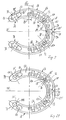
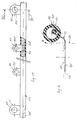
- the horseshoe according to the invention has a base part 10 shown in FIGS. 1 and 2. This consists of a horseshoe-shaped solid base body 12 and in recesses 14 of the base body 12 arranged, fastening elements 16 'forming fastening bolts 16th
- the horseshoe-shaped base body 12 made of metal, preferably of iron, has an essentially flat contact surface 18 on the upper side, which is intended to rest on a horse's hoof 20 (see FIG. 11).
- the cross section of the base body 12 is essentially rectangular or trapezoidal, with a circumferential edge bead 22 being provided, which protrudes over a substantially flat base surface 24 that runs parallel to the contact surface 18.
- the thickness of the base body, measured in the direction perpendicular to the contact surface 18, is approximately 6 mm from the latter to the base surface 24, the edge bead 22 protruding 1 mm to 3 mm, preferably approximately 2.5 mm, above the base surface 24.
- the base surface 24 extends from the front center of the base body 12 over both legs 26 to in each case one end section 28 of the legs 26, in which an oblique transition surface 30 adjoins the base surface 24, to which an end surface likewise essentially parallel to the contact surface 18 connects.
- the end surfaces 32 are offset relative to the base surface 24 in the direction towards the contact surface 18, so that the remaining wall thickness of the base body 12 between the end surfaces 32 and the contact surface 18 is preferably approximately 2.5 mm is.
- the end surface 32 and the side walls 34 adjoining it delimit an end recess 36, the width of which, measured at right angles to the longitudinal extension of the legs 26, approximately in the middle between the transition surface 30 and the end of the end recess 36 facing away from this tapers like a shoulder, so that it has an extension 38 with a smaller cross section.
- the side walls 34 are undercut in the region of the extension 38 to form a dovetail groove 40 in cross section, for example by milling. This groove 40 is closed at the free end of the extension 38 and is open towards the front in the wider area of the end recess 36.
- the two legs 26 each have a row, in the present case five, recesses 14 arranged one behind the other in the longitudinal direction of the legs, which recesses extend from the base surface 24 in the direction toward the contact surface 18 and are located in an area 42 which extends along the inner edge 42 of the base body 12.
- the essentially cylindrical or conically tapering recesses 14 are spaced from the edge 44 approximately by the thickness of the edge bead 22.
- the region 42 extends approximately over half the width of the base body 12, see also FIG. 3, and over approximately two thirds the length of the legs 26.
- the bottom of the recesses 14, which runs approximately parallel to the contact surface 18, is approximately 2 mm away from the latter .
- a fastening bolt 16 is arranged in each of the rearmost and the three frontmost recesses 14.
- these are commercially available thread welding bolts made of steel, which are copper-plated and are attached to the base body 12 by arc pressure welding. They protrude beyond the plane of the base surface 24 but end in the direction perpendicular to the contact surface 18 seen before the end of the edge bead 22; this protects the mounting bolts 16 from damage. It is of course conceivable, depending on the load, to arrange fastening bolts 16 in all recesses 14 or to omit them in other recesses 14.
- each leg 26 has a row of nail holes 46 arranged one behind the other in the longitudinal direction of the legs 26, in the present case four, each seen in the longitudinal direction of the legs 26 between adjacent recesses 14 and with respect to them in the direction are arranged offset to the outer edge 44 '.
- the nail holes 46 viewed in the direction perpendicular to the longitudinal direction of the legs 26, directly adjoin the area 42.
- the nail holes 46 preferably form frustoconical passages through the base body 12, so that commercially available E or IC hoof nails 48 can be used to attach the base body 12 (see also FIG. 11).
- the base body 12 has a depression 52 in the front region 50, in which the two legs 26, 26 ′ also abut one another, which is also shown in FIGS. 8 and 18.
- the front flank of the recess 52 is provided with an undercut 54.
- a toe cap 56 or side caps can be formed on the base body 12, as is generally known for horseshoes.
- a horseshoe-shaped sole 58 made of elastic, vibration and shock-absorbing and preferably abrasion-resistant material, for example a polyurethane, has, as this can be seen in particular from FIGS. 12 and 16, an essentially rectangular or trapezoidal cross-section.
- the footprint is designated by 60 and the support surface opposite it, facing the base body 12, with which the sole 58 mounted on the base part 10 bears against the base surface 24, with 62.
- a row of peg-like projections 68 protrudes above the support surface 62 in each leg 66 of the sole 58, which projections are intended to engage in the corresponding recesses 14 in the base body 12 when the sole 58 is installed.
- the projections are essentially cylindrical, possibly tapering towards the free end, as can be seen in particular from FIG. 17.
- Each projection 68 has a fastening recess 70 coaxial to its axis 68 ', the diameter of which is smaller than the diameter of the fastening bolts 16. If these are designed as threaded bolts, the diameter of the fastening recess 70 preferably corresponds approximately to the core diameter of the fastening bolts. A good frictional connection between them and the sole 58 is thereby achieved.
- a row of nail head recesses 72 is provided on each leg 66 of the sole 58, which are arranged corresponding to the nail holes 46 in the base body 12 in order to receive and enclose the parts of the heads 48 'of the horseshoe nails 48 projecting beyond the base surface 24.
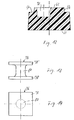
- a reinforcing member 76 is embedded in each of the free end regions 74 of the legs 66 in the sole 58, as shown in particular in FIGS. 13 to 16.
- Each reinforcing member 76 has two parallel, preferably square plates 78, which are connected to one another via a central shaft part 80.
- the lower plate 78 is embedded in the body of the sole 58, while the upper plate 78 'is arranged above the wing 62.
- the portion of the shaft portion 80 protruding above the body of the sole 58 is embedded in a wedge-like projection 82 of the sole 58, the width of which, viewed transversely to the longitudinal direction of the respective leg 66, is narrower than the plate 78, the upper surface 82 'of which is the upper surface the plate 78 'is aligned and which extends slightly in the longitudinal direction of the respective leg 66 in the direction towards its free end and in the direction towards the front beyond the upper plate 78'; the entire length of the wedge-like projection 82 corresponds approximately to the length of the end surface 32 in the base body 12.
- the plate 78 ' serves as part of a groove / wedge connection 84 of the sole 58 which cooperates with the groove 58 and the base part 10.
- the upper surface 82 ′ is arranged above the supporting surface 62 by approximately the same amount as the end surface 32 of the base body 12 is offset from the base surface 24.
- the holding extension 90 protrudes above the supporting surface 62 and is embedded in an engagement element 94 which is approximately adapted to the shape of the depression 52 and is formed on the sole 58, and projects with the holding lug 92 'above it.
- the likewise plate-like holding extension 90 for example welded onto the insert, has a passage 96 with a drop-shaped cross section approximately in the center, at the tapered end of which a cylindrical extension 96 'is formed, into which a heavy-duty spring pin 98 is inserted.
- the passage 96 penetrated by the material of the sole 58 and the heavy-duty spring pin 98 serve for the extremely stable fastening of the tread plate 88 to the sole 58.
- the sole 58 is mounted on the base body 12 as follows. First, the wedge-like projection 82 and the plate 78 'are inserted into the end recess 36 and the sole 58 is displaced towards the rear with respect to the base part 10 until the plate 78', which acts as a wedge, is at least partially caught in the groove 40. Then, by bending the sole 58, the engagement element 94 is brought into engagement with the depression 52, the holding extension 90 engaging in the undercut 54 in a hook-like manner. When the legs 66 of the sole 58 are subsequently pressed onto the base body 12, the plates 78 'are now pushed completely into the grooves 40 and the projections 68 of the sole 58 are inserted into the recesses in the base body 12. The fastening bolts 16 come into engagement with the fastening recesses 70 in order to achieve a good non-positive holding effect.
- the leg 26 is inserted between the sole 58 and the base part 10 with a tool, for example a screwdriver or pliers, in the middle region and the sole 58 underneath Bending lifted off the base part 10.
- a tool for example a screwdriver or pliers
- the holding extension 90 is also pivoted out of the depression 52, so that the engagement element 94 can be removed from the depression 52.
- the groove / wedge connection 84 with the two legs 26 can then be released by moving the sole 58 forward.
- the base part 10 is configured exactly the same as described above and shown in FIGS. 1 to 8.
- the sole 58 is also of the same design as shown in FIGS. 9, 12 and 17 to 20 and described above. 21 to 28, the same reference numerals are used for the same parts as in the embodiment described above.
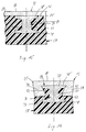
- the sole 58 has a through hole 104 in the embodiment according to FIGS. 21 to 28.
- a wedge-like projection 82 also protrudes in the end region 74 over the wing 62. This ends together with the wing 62 but at a distance in front of the through hole 104, the edge recess 64 at the end of the legs 66 forming end recesses 64 '.
- a stud insert 106 can be inserted into the through hole 104.
- This one Threaded sleeve 108 which is shown in FIGS. 24 to 26 in detail. It has an essentially cylindrical shaft section 110, to which a wedge plate 112 is formed at one end.
- a plate-like intermediate layer 114 can be placed on the wedge plate 112, which for fastening to the threaded sleeve 108 has a cylindrical fastening stub 116 which engages in the passage of the threaded sleeve 108 when the intermediate layer 114 is installed.
- a stud 118 can be screwed into the threaded sleeve 108, from the side facing away from the wedge plate 112, which is supported on the standing surface 60 of the sole 58 via a washer 120. By tightening the stud 118 to a certain torque, it builds up a pretension with the threaded sleeve 108 in the sole 58.
- the assembly of the stud insert 106 can be carried out as follows. First, the intermediate layer 114 of the threaded sleeve 108 is put on. The latter is then inserted into the through hole 104 of the sole 58 from the side facing the base part 10. Then the stud 118 with the washer 120 is screwed into the threaded sleeve 108 from the other side, but not yet tightened.
- the sole 58 can now be mounted together with the stud insert 106, as in the exemplary embodiment described above, to the base part 10 by inserting the wedge plate 112 into the groove 40 and then the engagement element 94 into the recess 52 in the front area 50 of the base part 10 is used.
- the sole 58 can also be installed by first inserting the threaded sleeve 108 with the intermediate layer 114 into the groove 40. Then the engaging element 94 is brought into engagement with the recess 52 and the sole 58 is placed against the base part 10 by pivoting about an axis perpendicular to the longitudinal center 58 ′, the fastening bolts 16 engaging with the fastening recesses 70 and the end regions 74 over the shaft section 110 of the threaded sleeve 108 is pushed. Finally, the desired stud 118 is then screwed into the threaded sleeve 108 with the washer 120 interposed, and tightened.
- the base part 10 and the sole 58 are connected to one another in the front region 50, 50 ′ and in the rear end regions 74 or end sections 28 by means of fastening means which can be retracted and extended into one another by bending the elastic sole 58 and which are positive in the direction transverse to the base part 10.
- fastening means which can be retracted and extended into one another by bending the elastic sole 58 and which are positive in the direction transverse to the base part 10.
- non-positive fastening means 16, 70 are present in the legs 26, 66, which hold the sole 58 in contact with the base part 10.
- In the solid base body 12 there are recesses 36, 52 and recesses 14 for receiving the fastening means.
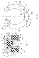
- FIGS. 1 to 8 and 21 to 28 FIGS. 29 and 30.
- Fastening eyelets 124 made of stainless spring steel sheet penetrate the wall of the snow protection insert 122 and are bent at their end arranged inside the snow protection insert 122 to form a spout 126.
- the fastening eyelets 124 each have an eyelet hole 124 'on the part which protrudes like a tongue from the snow protection insert 122.
- the sole 58 is first separated from the base part 10. Then the snow protection insert 122 is arranged along the inner edge of the sole 58 such that it runs along the inner edge 44 of the base part 10 when the sole 58 is installed, and the two middle fastening eyes 124 are each on the second front projection 68 of the two rows of projections Sole 58 pushed on, so that the projection in question passes through the eyelet hole 124 'of the fastening eyelet 124 in question, as is indicated by dashed lines in FIG. 30.
- the edge recess 64 is drawn further in the form of a fastening groove 130 encompassing the relevant projection 68 (see FIGS.
- the base body 12 is preferably produced by drop forging.
- the rows of recesses 14 and recesses for the rows of nail holes 46, the end recesses 36, the depression 52 and the edge bead 22 are also formed. All that is then required for finishing is removal, for example by milling, the groove 40 and the undercut 54, and the finishing of the nail holes 46, for example by cold stamping.
- the fastening bolts 16 are then welded to the recesses 14 in the monoblock-like base body 12.
Landscapes
- Life Sciences & Earth Sciences (AREA)
- Engineering & Computer Science (AREA)
- Wood Science & Technology (AREA)
- Zoology (AREA)
- Environmental Sciences (AREA)
- Footwear And Its Accessory, Manufacturing Method And Apparatuses (AREA)
- Medicines Containing Plant Substances (AREA)
Priority Applications (5)
| Application Number | Priority Date | Filing Date | Title |
|---|---|---|---|
| EP94100209A EP0662282B1 (fr) | 1994-01-08 | 1994-01-08 | Ferrure des sabots de cheval |
| DE59408517T DE59408517D1 (de) | 1994-01-08 | 1994-01-08 | Hufbeschlag |
| DK94100209T DK0662282T3 (da) | 1994-01-08 | 1994-01-08 | Hestesko |
| AT94100209T ATE182246T1 (de) | 1994-01-08 | 1994-01-08 | Hufbeschlag |
| US08/357,933 US5560428A (en) | 1994-01-08 | 1994-12-16 | Horseshoe with replaceable elements |
Applications Claiming Priority (1)
| Application Number | Priority Date | Filing Date | Title |
|---|---|---|---|
| EP94100209A EP0662282B1 (fr) | 1994-01-08 | 1994-01-08 | Ferrure des sabots de cheval |
Publications (2)
| Publication Number | Publication Date |
|---|---|
| EP0662282A1 true EP0662282A1 (fr) | 1995-07-12 |
| EP0662282B1 EP0662282B1 (fr) | 1999-07-21 |
Family
ID=8215591
Family Applications (1)
| Application Number | Title | Priority Date | Filing Date |
|---|---|---|---|
| EP94100209A Expired - Lifetime EP0662282B1 (fr) | 1994-01-08 | 1994-01-08 | Ferrure des sabots de cheval |
Country Status (5)
| Country | Link |
|---|---|
| US (1) | US5560428A (fr) |
| EP (1) | EP0662282B1 (fr) |
| AT (1) | ATE182246T1 (fr) |
| DE (1) | DE59408517D1 (fr) |
| DK (1) | DK0662282T3 (fr) |
Families Citing this family (4)
| Publication number | Priority date | Publication date | Assignee | Title |
|---|---|---|---|---|
| US6443232B1 (en) | 1998-06-04 | 2002-09-03 | Triple International Aps | Shock-absorbing horseshoe and a method of manufacturing such a horseshoe |
| US20090084560A1 (en) * | 2007-10-01 | 2009-04-02 | Kaylen Spooner | Quick install and quick release horseshoe calk and cleat |
| ES2358249B1 (es) * | 2009-07-31 | 2012-03-21 | Lujo Herraduras, S.L. | Herradura con soporte reutilizable perfeccionada. |
| US10306877B2 (en) * | 2011-11-03 | 2019-06-04 | Four Scorned, Llc | Removable insert for a horseshoe |
Citations (5)
| Publication number | Priority date | Publication date | Assignee | Title |
|---|---|---|---|---|
| GB230939A (en) * | 1923-12-28 | 1925-03-26 | Christopher Jordon | Improvements in horse shoes |
| FR2459614A1 (fr) * | 1979-06-27 | 1981-01-16 | Tweri International Ab | Fer a cheval |
| FR2512640A1 (fr) * | 1981-09-16 | 1983-03-18 | Meriel Marc | Fer antiderapant |
| WO1986005655A1 (fr) * | 1985-03-25 | 1986-10-09 | Juncker Knud Hoerup | Fer a cheval avec semelle remplaçable |
| EP0280656A1 (fr) * | 1987-02-24 | 1988-08-31 | Johann Meier | Dispositif pour empêcher l'agglomération de neige dans les fers à cheval |
Family Cites Families (8)
| Publication number | Priority date | Publication date | Assignee | Title |
|---|---|---|---|---|
| US458051A (en) * | 1891-08-18 | Horseshoe | ||
| US893201A (en) * | 1907-08-07 | 1908-07-14 | Thomas P Scully | Detachable horseshoe. |
| US1035530A (en) * | 1911-05-24 | 1912-08-13 | Francis A Bushey | Horseshoe. |
| US1155293A (en) * | 1915-07-21 | 1915-09-28 | William H Wilson | Non-slipping device. |
| US1612577A (en) * | 1924-09-15 | 1926-12-28 | Hall George Elden | Horseshoe |
| US3747684A (en) * | 1971-01-04 | 1973-07-24 | B Wallen | Elastic sole insert for horse shoes |
| DK157520C (da) * | 1982-05-19 | 1990-06-18 | Anders Jungersen | Todelt hestesko med elastisk underpart |
| US5105891A (en) * | 1990-12-10 | 1992-04-21 | Noffsinger Alfred A | Cushioned horseshoe |
-
1994
- 1994-01-08 EP EP94100209A patent/EP0662282B1/fr not_active Expired - Lifetime
- 1994-01-08 AT AT94100209T patent/ATE182246T1/de not_active IP Right Cessation
- 1994-01-08 DK DK94100209T patent/DK0662282T3/da active
- 1994-01-08 DE DE59408517T patent/DE59408517D1/de not_active Expired - Fee Related
- 1994-12-16 US US08/357,933 patent/US5560428A/en not_active Expired - Fee Related
Patent Citations (5)
| Publication number | Priority date | Publication date | Assignee | Title |
|---|---|---|---|---|
| GB230939A (en) * | 1923-12-28 | 1925-03-26 | Christopher Jordon | Improvements in horse shoes |
| FR2459614A1 (fr) * | 1979-06-27 | 1981-01-16 | Tweri International Ab | Fer a cheval |
| FR2512640A1 (fr) * | 1981-09-16 | 1983-03-18 | Meriel Marc | Fer antiderapant |
| WO1986005655A1 (fr) * | 1985-03-25 | 1986-10-09 | Juncker Knud Hoerup | Fer a cheval avec semelle remplaçable |
| EP0280656A1 (fr) * | 1987-02-24 | 1988-08-31 | Johann Meier | Dispositif pour empêcher l'agglomération de neige dans les fers à cheval |
Also Published As
| Publication number | Publication date |
|---|---|
| EP0662282B1 (fr) | 1999-07-21 |
| ATE182246T1 (de) | 1999-08-15 |
| DE59408517D1 (de) | 1999-08-26 |
| DK0662282T3 (da) | 1999-11-29 |
| US5560428A (en) | 1996-10-01 |
Similar Documents
| Publication | Publication Date | Title |
|---|---|---|
| EP0663843A1 (fr) | Appareil de sport a patin ou vehicule a patin a lame demontable. | |
| DE4104071A1 (de) | Sohle fuer sportschuhe und greifelement zur verbindung mit einer solchen sohle | |
| DE102006043763C5 (de) | Auswechselbares Verschleißpolster, sowie Gleiskette | |
| EP0181522A2 (fr) | Fer à cheval | |
| EP2618657B1 (fr) | Fer à cheval pour sabots de bête de selle, en particulier pour des chevaux, ainsi que partie de liaison et procédé pour la fabrication d'un tel fer à cheval | |
| EP0662282B1 (fr) | Ferrure des sabots de cheval | |
| EP0233335A2 (fr) | Fer à cheval | |
| DE69903023T2 (de) | Stossdämpfendes hufeisen und verfahren zur herstellung eines solchen hufeisens | |
| DE60208652T2 (de) | Verbesserter Hufschuh mit elastischer Zwischenschicht und Verfahren zu dessen Herstellung | |
| EP1307094B1 (fr) | Armature plastique en forme de plaque de type fer a cheval | |
| DE60212536T2 (de) | Radkeil für Industriefahrzeuge | |
| DE19959846A1 (de) | Stollen-System für Hufeisen | |
| DE4402662A1 (de) | Ski sowie Bindungsplatte für einen Ski | |
| DE29718933U1 (de) | Hufeisen | |
| EP0893057A1 (fr) | Fer à cheval ouvert en matériel synthétique | |
| DE3526298A1 (de) | Schuh, insbesondere sportschuh mit austauschbarem laufsohlenteil | |
| DE202019105986U1 (de) | Hufschutzsystem | |
| CH672573A5 (fr) | ||
| DE102015105341A1 (de) | Insertverbundstruktur | |
| AT402136B (de) | Hufeiseneinlage | |
| DE9644C (de) | Neuerungen in der Konstruktion und Befestigungsweise von Hufeisen | |
| DE10303483A1 (de) | Kettensteg für eine Laufkette eines Kettenfahrzeugs | |
| DE3300330A1 (de) | Sportschuh mit haltestegen und auswechselbaren beschlaegen | |
| DE3928341A1 (de) | Hufeisen | |
| DE102004026191A1 (de) | Hufeisen |
Legal Events
| Date | Code | Title | Description |
|---|---|---|---|
| PUAI | Public reference made under article 153(3) epc to a published international application that has entered the european phase |
Free format text: ORIGINAL CODE: 0009012 |
|
| AK | Designated contracting states |
Kind code of ref document: A1 Designated state(s): AT BE CH DE DK FR GB IE IT LI NL SE |
|
| 17P | Request for examination filed |
Effective date: 19960102 |
|
| 17Q | First examination report despatched |
Effective date: 19980123 |
|
| GRAG | Despatch of communication of intention to grant |
Free format text: ORIGINAL CODE: EPIDOS AGRA |
|
| GRAG | Despatch of communication of intention to grant |
Free format text: ORIGINAL CODE: EPIDOS AGRA |
|
| GRAG | Despatch of communication of intention to grant |
Free format text: ORIGINAL CODE: EPIDOS AGRA |
|
| GRAH | Despatch of communication of intention to grant a patent |
Free format text: ORIGINAL CODE: EPIDOS IGRA |
|
| GRAH | Despatch of communication of intention to grant a patent |
Free format text: ORIGINAL CODE: EPIDOS IGRA |
|
| RAP1 | Party data changed (applicant data changed or rights of an application transferred) |
Owner name: PRECOTEC AG |
|
| GRAA | (expected) grant |
Free format text: ORIGINAL CODE: 0009210 |
|
| AK | Designated contracting states |
Kind code of ref document: B1 Designated state(s): AT BE CH DE DK FR GB IE IT LI NL SE |
|
| REF | Corresponds to: |
Ref document number: 182246 Country of ref document: AT Date of ref document: 19990815 Kind code of ref document: T |
|
| REG | Reference to a national code |
Ref country code: CH Ref legal event code: NV Representative=s name: PATENTANWAELTE SCHAAD, BALASS, MENZL & PARTNER AG Ref country code: CH Ref legal event code: EP |
|
| REF | Corresponds to: |
Ref document number: 59408517 Country of ref document: DE Date of ref document: 19990826 |
|
| REG | Reference to a national code |
Ref country code: IE Ref legal event code: FG4D Free format text: GERMAN |
|
| ITF | It: translation for a ep patent filed | ||
| GBT | Gb: translation of ep patent filed (gb section 77(6)(a)/1977) |
Effective date: 19990921 |
|
| ET | Fr: translation filed | ||
| REG | Reference to a national code |
Ref country code: DK Ref legal event code: T3 |
|
| PLBE | No opposition filed within time limit |
Free format text: ORIGINAL CODE: 0009261 |
|
| STAA | Information on the status of an ep patent application or granted ep patent |
Free format text: STATUS: NO OPPOSITION FILED WITHIN TIME LIMIT |
|
| 26N | No opposition filed | ||
| REG | Reference to a national code |
Ref country code: GB Ref legal event code: IF02 |
|
| PG25 | Lapsed in a contracting state [announced via postgrant information from national office to epo] |
Ref country code: IT Free format text: LAPSE BECAUSE OF NON-PAYMENT OF DUE FEES Effective date: 20050108 |
|
| PGFP | Annual fee paid to national office [announced via postgrant information from national office to epo] |
Ref country code: SE Payment date: 20050120 Year of fee payment: 12 |
|
| PGFP | Annual fee paid to national office [announced via postgrant information from national office to epo] |
Ref country code: NL Payment date: 20050121 Year of fee payment: 12 Ref country code: AT Payment date: 20050121 Year of fee payment: 12 |
|
| PGFP | Annual fee paid to national office [announced via postgrant information from national office to epo] |
Ref country code: FR Payment date: 20050124 Year of fee payment: 12 Ref country code: DK Payment date: 20050124 Year of fee payment: 12 |
|
| PGFP | Annual fee paid to national office [announced via postgrant information from national office to epo] |
Ref country code: IE Payment date: 20050126 Year of fee payment: 12 |
|
| PGFP | Annual fee paid to national office [announced via postgrant information from national office to epo] |
Ref country code: BE Payment date: 20050302 Year of fee payment: 12 |
|
| PG25 | Lapsed in a contracting state [announced via postgrant information from national office to epo] |
Ref country code: AT Free format text: LAPSE BECAUSE OF NON-PAYMENT OF DUE FEES Effective date: 20060108 |
|
| PG25 | Lapsed in a contracting state [announced via postgrant information from national office to epo] |
Ref country code: SE Free format text: LAPSE BECAUSE OF NON-PAYMENT OF DUE FEES Effective date: 20060109 Ref country code: IE Free format text: LAPSE BECAUSE OF NON-PAYMENT OF DUE FEES Effective date: 20060109 |
|
| PGFP | Annual fee paid to national office [announced via postgrant information from national office to epo] |
Ref country code: GB Payment date: 20060120 Year of fee payment: 13 |
|
| PG25 | Lapsed in a contracting state [announced via postgrant information from national office to epo] |
Ref country code: FR Free format text: LAPSE BECAUSE OF NON-PAYMENT OF DUE FEES Effective date: 20060131 Ref country code: DK Free format text: LAPSE BECAUSE OF NON-PAYMENT OF DUE FEES Effective date: 20060131 Ref country code: BE Free format text: LAPSE BECAUSE OF NON-PAYMENT OF DUE FEES Effective date: 20060131 |
|
| PGFP | Annual fee paid to national office [announced via postgrant information from national office to epo] |
Ref country code: CH Payment date: 20060131 Year of fee payment: 13 |
|
| PGFP | Annual fee paid to national office [announced via postgrant information from national office to epo] |
Ref country code: DE Payment date: 20060214 Year of fee payment: 13 |
|
| PG25 | Lapsed in a contracting state [announced via postgrant information from national office to epo] |
Ref country code: NL Free format text: LAPSE BECAUSE OF NON-PAYMENT OF DUE FEES Effective date: 20060801 |
|
| REG | Reference to a national code |
Ref country code: DK Ref legal event code: EBP |
|
| EUG | Se: european patent has lapsed | ||
| NLV4 | Nl: lapsed or anulled due to non-payment of the annual fee |
Effective date: 20060801 |
|
| REG | Reference to a national code |
Ref country code: IE Ref legal event code: MM4A |
|
| REG | Reference to a national code |
Ref country code: FR Ref legal event code: ST Effective date: 20060929 |
|
| PG25 | Lapsed in a contracting state [announced via postgrant information from national office to epo] |
Ref country code: LI Free format text: LAPSE BECAUSE OF NON-PAYMENT OF DUE FEES Effective date: 20070131 Ref country code: CH Free format text: LAPSE BECAUSE OF NON-PAYMENT OF DUE FEES Effective date: 20070131 |
|
| PG25 | Lapsed in a contracting state [announced via postgrant information from national office to epo] |
Ref country code: DE Free format text: LAPSE BECAUSE OF NON-PAYMENT OF DUE FEES Effective date: 20070801 |
|
| REG | Reference to a national code |
Ref country code: CH Ref legal event code: PL |
|
| GBPC | Gb: european patent ceased through non-payment of renewal fee |
Effective date: 20070108 |
|
| PG25 | Lapsed in a contracting state [announced via postgrant information from national office to epo] |
Ref country code: GB Free format text: LAPSE BECAUSE OF NON-PAYMENT OF DUE FEES Effective date: 20070108 |
|
| BERE | Be: lapsed |
Owner name: *PRECOTEC A.G. Effective date: 20060131 |
|
| PGFP | Annual fee paid to national office [announced via postgrant information from national office to epo] |
Ref country code: IT Payment date: 20060131 Year of fee payment: 13 |
|
| PGRI | Patent reinstated in contracting state [announced from national office to epo] |
Ref country code: IT Effective date: 20080301 |
|
| PGRI | Patent reinstated in contracting state [announced from national office to epo] |
Ref country code: IT Effective date: 20080301 |