EP0662356A2 - Procédé et dispositif d'entraînement d'un générateur pour l'alimentation d'énergie HF d'un transducteur à ultrason - Google Patents
Procédé et dispositif d'entraînement d'un générateur pour l'alimentation d'énergie HF d'un transducteur à ultrason Download PDFInfo
- Publication number
- EP0662356A2 EP0662356A2 EP95100122A EP95100122A EP0662356A2 EP 0662356 A2 EP0662356 A2 EP 0662356A2 EP 95100122 A EP95100122 A EP 95100122A EP 95100122 A EP95100122 A EP 95100122A EP 0662356 A2 EP0662356 A2 EP 0662356A2
- Authority
- EP
- European Patent Office
- Prior art keywords
- phase
- generator
- frequency
- control
- die
- Prior art date
- Legal status (The legal status is an assumption and is not a legal conclusion. Google has not performed a legal analysis and makes no representation as to the accuracy of the status listed.)
- Granted
Links
- 238000000034 method Methods 0.000 title claims abstract description 53
- 238000002604 ultrasonography Methods 0.000 title claims description 12
- 238000003466 welding Methods 0.000 claims abstract description 30
- 230000001105 regulatory effect Effects 0.000 claims abstract description 8
- 230000006978 adaptation Effects 0.000 claims description 10
- 230000006870 function Effects 0.000 claims description 8
- 230000010355 oscillation Effects 0.000 claims description 7
- 230000008859 change Effects 0.000 claims description 5
- 230000001419 dependent effect Effects 0.000 claims description 5
- 239000002184 metal Substances 0.000 claims description 5
- 230000004044 response Effects 0.000 claims description 2
- 238000003754 machining Methods 0.000 claims 1
- 230000008569 process Effects 0.000 abstract description 20
- 238000004519 manufacturing process Methods 0.000 abstract 2
- 230000008901 benefit Effects 0.000 description 5
- 238000005259 measurement Methods 0.000 description 5
- 239000003990 capacitor Substances 0.000 description 4
- 238000010586 diagram Methods 0.000 description 4
- 230000007704 transition Effects 0.000 description 4
- 238000012544 monitoring process Methods 0.000 description 3
- 230000000630 rising effect Effects 0.000 description 3
- 238000004140 cleaning Methods 0.000 description 2
- 230000001276 controlling effect Effects 0.000 description 2
- 230000006378 damage Effects 0.000 description 2
- 238000013461 design Methods 0.000 description 2
- 239000000463 material Substances 0.000 description 2
- 238000001228 spectrum Methods 0.000 description 2
- 238000004506 ultrasonic cleaning Methods 0.000 description 2
- 230000009471 action Effects 0.000 description 1
- 230000000712 assembly Effects 0.000 description 1
- 238000000429 assembly Methods 0.000 description 1
- 230000008878 coupling Effects 0.000 description 1
- 238000010168 coupling process Methods 0.000 description 1
- 238000005859 coupling reaction Methods 0.000 description 1
- 238000007872 degassing Methods 0.000 description 1
- 238000011161 development Methods 0.000 description 1
- 230000018109 developmental process Effects 0.000 description 1
- 230000005284 excitation Effects 0.000 description 1
- 238000007667 floating Methods 0.000 description 1
- 239000002655 kraft paper Substances 0.000 description 1
- 239000007788 liquid Substances 0.000 description 1
- 238000004806 packaging method and process Methods 0.000 description 1
- 230000010363 phase shift Effects 0.000 description 1
- 230000000704 physical effect Effects 0.000 description 1
- 238000004886 process control Methods 0.000 description 1
- 230000009993 protective function Effects 0.000 description 1
- 230000035484 reaction time Effects 0.000 description 1
Images




Classifications
-
- B—PERFORMING OPERATIONS; TRANSPORTING
- B29—WORKING OF PLASTICS; WORKING OF SUBSTANCES IN A PLASTIC STATE IN GENERAL
- B29C—SHAPING OR JOINING OF PLASTICS; SHAPING OF MATERIAL IN A PLASTIC STATE, NOT OTHERWISE PROVIDED FOR; AFTER-TREATMENT OF THE SHAPED PRODUCTS, e.g. REPAIRING
- B29C65/00—Joining or sealing of preformed parts, e.g. welding of plastics materials; Apparatus therefor
- B29C65/02—Joining or sealing of preformed parts, e.g. welding of plastics materials; Apparatus therefor by heating, with or without pressure
- B29C65/08—Joining or sealing of preformed parts, e.g. welding of plastics materials; Apparatus therefor by heating, with or without pressure using ultrasonic vibrations
-
- G—PHYSICS
- G01—MEASURING; TESTING
- G01R—MEASURING ELECTRIC VARIABLES; MEASURING MAGNETIC VARIABLES
- G01R25/00—Arrangements for measuring phase angle between a voltage and a current or between voltages or currents
-
- B—PERFORMING OPERATIONS; TRANSPORTING
- B06—GENERATING OR TRANSMITTING MECHANICAL VIBRATIONS IN GENERAL
- B06B—METHODS OR APPARATUS FOR GENERATING OR TRANSMITTING MECHANICAL VIBRATIONS OF INFRASONIC, SONIC, OR ULTRASONIC FREQUENCY, e.g. FOR PERFORMING MECHANICAL WORK IN GENERAL
- B06B1/00—Methods or apparatus for generating mechanical vibrations of infrasonic, sonic, or ultrasonic frequency
- B06B1/02—Methods or apparatus for generating mechanical vibrations of infrasonic, sonic, or ultrasonic frequency making use of electrical energy
- B06B1/0207—Driving circuits
- B06B1/0223—Driving circuits for generating signals continuous in time
- B06B1/0238—Driving circuits for generating signals continuous in time of a single frequency, e.g. a sine-wave
- B06B1/0246—Driving circuits for generating signals continuous in time of a single frequency, e.g. a sine-wave with a feedback signal
- B06B1/0253—Driving circuits for generating signals continuous in time of a single frequency, e.g. a sine-wave with a feedback signal taken directly from the generator circuit
-
- B—PERFORMING OPERATIONS; TRANSPORTING
- B29—WORKING OF PLASTICS; WORKING OF SUBSTANCES IN A PLASTIC STATE IN GENERAL
- B29C—SHAPING OR JOINING OF PLASTICS; SHAPING OF MATERIAL IN A PLASTIC STATE, NOT OTHERWISE PROVIDED FOR; AFTER-TREATMENT OF THE SHAPED PRODUCTS, e.g. REPAIRING
- B29C66/00—General aspects of processes or apparatus for joining preformed parts
- B29C66/90—Measuring or controlling the joining process
- B29C66/95—Measuring or controlling the joining process by measuring or controlling specific variables not covered by groups B29C66/91 - B29C66/94
- B29C66/951—Measuring or controlling the joining process by measuring or controlling specific variables not covered by groups B29C66/91 - B29C66/94 by measuring or controlling the vibration frequency and/or the vibration amplitude of vibrating joining tools, e.g. of ultrasonic welding tools
- B29C66/9512—Measuring or controlling the joining process by measuring or controlling specific variables not covered by groups B29C66/91 - B29C66/94 by measuring or controlling the vibration frequency and/or the vibration amplitude of vibrating joining tools, e.g. of ultrasonic welding tools by controlling their vibration frequency
-
- B—PERFORMING OPERATIONS; TRANSPORTING
- B29—WORKING OF PLASTICS; WORKING OF SUBSTANCES IN A PLASTIC STATE IN GENERAL
- B29C—SHAPING OR JOINING OF PLASTICS; SHAPING OF MATERIAL IN A PLASTIC STATE, NOT OTHERWISE PROVIDED FOR; AFTER-TREATMENT OF THE SHAPED PRODUCTS, e.g. REPAIRING
- B29C66/00—General aspects of processes or apparatus for joining preformed parts
- B29C66/90—Measuring or controlling the joining process
- B29C66/95—Measuring or controlling the joining process by measuring or controlling specific variables not covered by groups B29C66/91 - B29C66/94
- B29C66/959—Measuring or controlling the joining process by measuring or controlling specific variables not covered by groups B29C66/91 - B29C66/94 characterised by specific values or ranges of said specific variables
- B29C66/9592—Measuring or controlling the joining process by measuring or controlling specific variables not covered by groups B29C66/91 - B29C66/94 characterised by specific values or ranges of said specific variables in explicit relation to another variable, e.g. X-Y diagrams
-
- B—PERFORMING OPERATIONS; TRANSPORTING
- B29—WORKING OF PLASTICS; WORKING OF SUBSTANCES IN A PLASTIC STATE IN GENERAL
- B29C—SHAPING OR JOINING OF PLASTICS; SHAPING OF MATERIAL IN A PLASTIC STATE, NOT OTHERWISE PROVIDED FOR; AFTER-TREATMENT OF THE SHAPED PRODUCTS, e.g. REPAIRING
- B29C66/00—General aspects of processes or apparatus for joining preformed parts
- B29C66/90—Measuring or controlling the joining process
- B29C66/96—Measuring or controlling the joining process characterised by the method for implementing the controlling of the joining process
- B29C66/961—Measuring or controlling the joining process characterised by the method for implementing the controlling of the joining process involving a feedback loop mechanism, e.g. comparison with a desired value
-
- B—PERFORMING OPERATIONS; TRANSPORTING
- B06—GENERATING OR TRANSMITTING MECHANICAL VIBRATIONS IN GENERAL
- B06B—METHODS OR APPARATUS FOR GENERATING OR TRANSMITTING MECHANICAL VIBRATIONS OF INFRASONIC, SONIC, OR ULTRASONIC FREQUENCY, e.g. FOR PERFORMING MECHANICAL WORK IN GENERAL
- B06B2201/00—Indexing scheme associated with B06B1/0207 for details covered by B06B1/0207 but not provided for in any of its subgroups
- B06B2201/70—Specific application
- B06B2201/72—Welding, joining, soldering
-
- B—PERFORMING OPERATIONS; TRANSPORTING
- B29—WORKING OF PLASTICS; WORKING OF SUBSTANCES IN A PLASTIC STATE IN GENERAL
- B29C—SHAPING OR JOINING OF PLASTICS; SHAPING OF MATERIAL IN A PLASTIC STATE, NOT OTHERWISE PROVIDED FOR; AFTER-TREATMENT OF THE SHAPED PRODUCTS, e.g. REPAIRING
- B29C66/00—General aspects of processes or apparatus for joining preformed parts
- B29C66/90—Measuring or controlling the joining process
- B29C66/91—Measuring or controlling the joining process by measuring or controlling the temperature, the heat or the thermal flux
- B29C66/912—Measuring or controlling the joining process by measuring or controlling the temperature, the heat or the thermal flux by measuring the temperature, the heat or the thermal flux
- B29C66/9121—Measuring or controlling the joining process by measuring or controlling the temperature, the heat or the thermal flux by measuring the temperature, the heat or the thermal flux by measuring the temperature
- B29C66/91231—Measuring or controlling the joining process by measuring or controlling the temperature, the heat or the thermal flux by measuring the temperature, the heat or the thermal flux by measuring the temperature of the joining tool
-
- B—PERFORMING OPERATIONS; TRANSPORTING
- B29—WORKING OF PLASTICS; WORKING OF SUBSTANCES IN A PLASTIC STATE IN GENERAL
- B29C—SHAPING OR JOINING OF PLASTICS; SHAPING OF MATERIAL IN A PLASTIC STATE, NOT OTHERWISE PROVIDED FOR; AFTER-TREATMENT OF THE SHAPED PRODUCTS, e.g. REPAIRING
- B29C66/00—General aspects of processes or apparatus for joining preformed parts
- B29C66/90—Measuring or controlling the joining process
- B29C66/91—Measuring or controlling the joining process by measuring or controlling the temperature, the heat or the thermal flux
- B29C66/914—Measuring or controlling the joining process by measuring or controlling the temperature, the heat or the thermal flux by controlling or regulating the temperature, the heat or the thermal flux
- B29C66/9141—Measuring or controlling the joining process by measuring or controlling the temperature, the heat or the thermal flux by controlling or regulating the temperature, the heat or the thermal flux by controlling or regulating the temperature
- B29C66/91421—Measuring or controlling the joining process by measuring or controlling the temperature, the heat or the thermal flux by controlling or regulating the temperature, the heat or the thermal flux by controlling or regulating the temperature of the joining tools
-
- B—PERFORMING OPERATIONS; TRANSPORTING
- B29—WORKING OF PLASTICS; WORKING OF SUBSTANCES IN A PLASTIC STATE IN GENERAL
- B29C—SHAPING OR JOINING OF PLASTICS; SHAPING OF MATERIAL IN A PLASTIC STATE, NOT OTHERWISE PROVIDED FOR; AFTER-TREATMENT OF THE SHAPED PRODUCTS, e.g. REPAIRING
- B29C66/00—General aspects of processes or apparatus for joining preformed parts
- B29C66/90—Measuring or controlling the joining process
- B29C66/91—Measuring or controlling the joining process by measuring or controlling the temperature, the heat or the thermal flux
- B29C66/919—Measuring or controlling the joining process by measuring or controlling the temperature, the heat or the thermal flux characterised by specific temperature, heat or thermal flux values or ranges
-
- B—PERFORMING OPERATIONS; TRANSPORTING
- B29—WORKING OF PLASTICS; WORKING OF SUBSTANCES IN A PLASTIC STATE IN GENERAL
- B29C—SHAPING OR JOINING OF PLASTICS; SHAPING OF MATERIAL IN A PLASTIC STATE, NOT OTHERWISE PROVIDED FOR; AFTER-TREATMENT OF THE SHAPED PRODUCTS, e.g. REPAIRING
- B29C66/00—General aspects of processes or apparatus for joining preformed parts
- B29C66/90—Measuring or controlling the joining process
- B29C66/92—Measuring or controlling the joining process by measuring or controlling the pressure, the force, the mechanical power or the displacement of the joining tools
- B29C66/922—Measuring or controlling the joining process by measuring or controlling the pressure, the force, the mechanical power or the displacement of the joining tools by measuring the pressure, the force, the mechanical power or the displacement of the joining tools
- B29C66/9221—Measuring or controlling the joining process by measuring or controlling the pressure, the force, the mechanical power or the displacement of the joining tools by measuring the pressure, the force, the mechanical power or the displacement of the joining tools by measuring the pressure, the force or the mechanical power
-
- B—PERFORMING OPERATIONS; TRANSPORTING
- B29—WORKING OF PLASTICS; WORKING OF SUBSTANCES IN A PLASTIC STATE IN GENERAL
- B29C—SHAPING OR JOINING OF PLASTICS; SHAPING OF MATERIAL IN A PLASTIC STATE, NOT OTHERWISE PROVIDED FOR; AFTER-TREATMENT OF THE SHAPED PRODUCTS, e.g. REPAIRING
- B29C66/00—General aspects of processes or apparatus for joining preformed parts
- B29C66/90—Measuring or controlling the joining process
- B29C66/92—Measuring or controlling the joining process by measuring or controlling the pressure, the force, the mechanical power or the displacement of the joining tools
- B29C66/924—Measuring or controlling the joining process by measuring or controlling the pressure, the force, the mechanical power or the displacement of the joining tools by controlling or regulating the pressure, the force, the mechanical power or the displacement of the joining tools
- B29C66/9241—Measuring or controlling the joining process by measuring or controlling the pressure, the force, the mechanical power or the displacement of the joining tools by controlling or regulating the pressure, the force, the mechanical power or the displacement of the joining tools by controlling or regulating the pressure, the force or the mechanical power
- B29C66/92431—Measuring or controlling the joining process by measuring or controlling the pressure, the force, the mechanical power or the displacement of the joining tools by controlling or regulating the pressure, the force, the mechanical power or the displacement of the joining tools by controlling or regulating the pressure, the force or the mechanical power the pressure, the force or the mechanical power being kept constant over time
-
- B—PERFORMING OPERATIONS; TRANSPORTING
- B29—WORKING OF PLASTICS; WORKING OF SUBSTANCES IN A PLASTIC STATE IN GENERAL
- B29C—SHAPING OR JOINING OF PLASTICS; SHAPING OF MATERIAL IN A PLASTIC STATE, NOT OTHERWISE PROVIDED FOR; AFTER-TREATMENT OF THE SHAPED PRODUCTS, e.g. REPAIRING
- B29C66/00—General aspects of processes or apparatus for joining preformed parts
- B29C66/90—Measuring or controlling the joining process
- B29C66/94—Measuring or controlling the joining process by measuring or controlling the time
- B29C66/944—Measuring or controlling the joining process by measuring or controlling the time by controlling or regulating the time
-
- B—PERFORMING OPERATIONS; TRANSPORTING
- B29—WORKING OF PLASTICS; WORKING OF SUBSTANCES IN A PLASTIC STATE IN GENERAL
- B29C—SHAPING OR JOINING OF PLASTICS; SHAPING OF MATERIAL IN A PLASTIC STATE, NOT OTHERWISE PROVIDED FOR; AFTER-TREATMENT OF THE SHAPED PRODUCTS, e.g. REPAIRING
- B29C66/00—General aspects of processes or apparatus for joining preformed parts
- B29C66/90—Measuring or controlling the joining process
- B29C66/95—Measuring or controlling the joining process by measuring or controlling specific variables not covered by groups B29C66/91 - B29C66/94
- B29C66/951—Measuring or controlling the joining process by measuring or controlling specific variables not covered by groups B29C66/91 - B29C66/94 by measuring or controlling the vibration frequency and/or the vibration amplitude of vibrating joining tools, e.g. of ultrasonic welding tools
- B29C66/9513—Measuring or controlling the joining process by measuring or controlling specific variables not covered by groups B29C66/91 - B29C66/94 by measuring or controlling the vibration frequency and/or the vibration amplitude of vibrating joining tools, e.g. of ultrasonic welding tools characterised by specific vibration frequency values or ranges
-
- B—PERFORMING OPERATIONS; TRANSPORTING
- B29—WORKING OF PLASTICS; WORKING OF SUBSTANCES IN A PLASTIC STATE IN GENERAL
- B29C—SHAPING OR JOINING OF PLASTICS; SHAPING OF MATERIAL IN A PLASTIC STATE, NOT OTHERWISE PROVIDED FOR; AFTER-TREATMENT OF THE SHAPED PRODUCTS, e.g. REPAIRING
- B29C66/00—General aspects of processes or apparatus for joining preformed parts
- B29C66/90—Measuring or controlling the joining process
- B29C66/95—Measuring or controlling the joining process by measuring or controlling specific variables not covered by groups B29C66/91 - B29C66/94
- B29C66/951—Measuring or controlling the joining process by measuring or controlling specific variables not covered by groups B29C66/91 - B29C66/94 by measuring or controlling the vibration frequency and/or the vibration amplitude of vibrating joining tools, e.g. of ultrasonic welding tools
- B29C66/9516—Measuring or controlling the joining process by measuring or controlling specific variables not covered by groups B29C66/91 - B29C66/94 by measuring or controlling the vibration frequency and/or the vibration amplitude of vibrating joining tools, e.g. of ultrasonic welding tools by controlling their vibration amplitude
Definitions
- the invention relates to a method and a device for operating a generator for HF energy supply to an ultrasound transducer according to the preamble of patent claim 1 and of patent claim 24.
- the state of the art can be found in numerous patents, including in US 4,973,876.
- the RF frequency for the ultrasound transducer is generated in a pulse-width-modulated converter and the frequency of the converter is adjusted depending on the phase angle between current and voltage at the output of the RF generator.
- the control circuit works analogously and requires a corresponding effort, in particular to filter the current signal and to process it in a phase circuit in such a way that the generator frequency is adjusted to a value at which the phase angle between current and voltage has a zero crossing, which is characteristic of the resonance state is.
- the control is rigid, ie it cannot adapt to the physical properties of the converter system in order to obtain optimal control properties. This can cause problems with transducers with high quality and those with low quality or transducers with a very steep transition between series and parallel resonance.
- the tune range cannot be changed, which is a problem with disturbing secondary resonances, since these cannot be hidden.
- the tune range must be preset to be as close as possible to the operating frequency, because otherwise the high reactive current component in the output stage leads to overload.
- the invention is therefore based on the object of specifying a method and a device with the aim of finding and regulating the frequency of the generator for the desired resonance state more quickly and reliably, even in complex systems, to improve the control, to stabilize it and to adapt it optimally to achieve the ultrasound system ..
- phase angle not only the phase angle, but also additional control variables such as current, voltage, apparent power and active power are used for the frequency control of the generator.
- control variables such as current, voltage, apparent power and active power are used for the frequency control of the generator.
- These values are processed and linked digitally in a microcontroller, which is capable of registering several parameters in addition to the phase angle, evaluating them and using them to form the correct control variable for controlling the generator.
- the choice of suitable parameters and the permissible parameter ranges, as well as the adjustment of the measurement resolution to the acoustic conditions of the system is of central importance for the optimal frequency control and tracking. Simply linking several measured values enables the control to to find and regulate the desired resonance state optimally, and thus to avoid the excitation of undesired secondary resonances.
- the physically correct control is therefore a control that uses the phase as a controlled variable or combinations of the phase with other controlled variables such as apparent power, current etc.
- the digital phase control is also able to regulate systems that do not have a phase zero crossing, which results in a wider field of application than with analog phase control.
- the phase minimum is regulated or a phase zero crossing is simulated by a phase offset.
- the measurement of the current curve over the frequency at idle provides the microcontroller with information about the position of the resonance point and any secondary resonances that may be present. He can then design and place the tune area so that manual adjustment is not necessary.
- Finding the right working point and optimal readjustment is therefore a central theme of the invention.
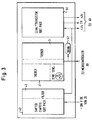
- the line filter 10 for protecting the network from high-frequency interference
- the main power supply 20 for the voltage supply of the individual components
- the output stage 50 with shifter 40 for generating an output power and output frequency defined by the microcontroller
- the matching stage 60 to match the impedance of the ultrasonic transducer
- the microcontroller 80 for controlling the welding process and monitoring the generator electronics.
- the mains voltage is fed to the main power supply 20 via the mains filter 10.
- the main power supply 20 supplies the supply voltage of 300 V to the shifter 40 and notifies the microcontroller 80 of its switched-on state, so that the output stage 50 is only activated by the microcontroller 80 when all components have built up their operating voltage. Only then is a defined state achieved, which enables the microcontroller to control the generator.
- the shifter 40 is a chopper in which the DC voltage from the main power supply 20 is converted into a pulse frequency sequence in which the pulse width determines the output amplitude.
- the shifter 40 prepares the DC voltage and thus the power that is switched through by the output stage 50.
- the power level is determined by the microcontroller by modulating the pulse width generated by the shifter.
- the output of the output stage is finally matched in impedance to the converter system via the adaptation stage 60.
- the transducer system is an ultrasound transducer (not shown) in connection with an amplitude transformer or a sonotrode.
- the output stage 50 returns the information about the output power and the oscillation frequency to the microcontroller 80.
- the microcontroller itself has the task of finding the optimum working point from the information about current and voltage supplied to it from the output of the adaptation stage 60 and of introducing the energy into the welding process.
- the microcontroller also controls the switch-on state and the permissible currents in the different components.
- a master relay 21 enables the main power supply unit to be completely disconnected from the network. This happens, for example, if it is too high Power consumption of the power supply.
- a power supply switch controller 22 is provided for registering and monitoring protective functions and is supplied with a 24 V operating voltage by a DC power supply 23. The DC Power Supply is switched on with a key switch. The switch controller provides a switch-on delay of approx. 1 sec. The microcontroller needs this time for initialization. The operating voltage for the shifter 40 is therefore only reached when the microcontroller has reached a defined state. This protects the amplifier 50 from extreme conditions.
- the voltage is fed via a rectifier 24 to a relay 25 which is connected in parallel with a starting resistor.
- the filter capacitors 26 are charged via the starting resistor.
- the voltage of the filter capacitors 26 is fed to the relay 25 via a voltage divider 27.
- the relay 25 switches through when the applied voltage has reached a certain value.
- the starting resistor is then bridged by the relay 25 and the rectified voltage is thus fed directly to the filter capacitors 26. This ensures that the supply voltage for the shifter 40 builds up slowly when the generator is switched on.
- the switch-on voltage U (NT) is reported back to the microcontroller 80, so that the shifter 40 is only activated when U (NT) has reached the nominal value.
- the alternating current is measured in front of the rectifier 24 and fed to the switch controller 22. If the current is too high, the switch controller 22 closes the master relay 21 and thereby protects the generator from destruction. At the same time, the soft start relay 25 is closed, as a result of which the internal resistance of the main power supply 20 becomes high-resistance.
- the AC voltage at the input of the full bridge rectifier 24 is fed to a second rectifier 28, which supplies a 12 V stabilized voltage both for the driver stage of the chopper 40 and for the drivers of the output stage transistors 50.
- the master relay 21 is also switched off by the switch controller 22 when the temperature below the circuit board exceeds 75 ° C.
- a further protection of the generator against overload is provided by the measurement of the current to the ultrasound transducer at the output of the adaptation 60.
- the microcontroller 80 can control the switch controller 22 in a floating manner and move it to switch off the master relay 21.
- the switch controller 22 is activated with a galvanically isolated signal for switching off the master relay 21 in the event of any microcontroller error.
- the switch controller 22 will also switch on the parallel resistance of the soft start relay 25 in order to obtain a high-resistance internal resistance of the main power supply 20.
- a DC voltage converter 29 supplied with 12 V stabilized voltage integrates the pulses coming from the output stage 50 and forwards a potential-free voltage information to the microcontroller 80. Based on this information, the microcontroller recognizes to what extent the voltage at the shifter output has built up and can react if necessary.
- the power stage consists of three parts, the shifter 40, which chops the voltage supplied to it and re-integrates it into capacitors (not shown), the switching transistors 50 Generation of the oscillation frequency and the driver electronics 41, 51, which drives both the switching transistors of the shifter 40 and the half-bridge of the frequency-determining part.
- the microcontroller 80 determines the pulse width of the shifter pulses and thus the voltage potential emitted after the filter 42, which in turn determines the power emitted by the half-bridge (output stage 50) to the adaptation 60.
- the voltage potential applied to the half-bridge can be connected to ground controlled by the microcontroller via a drain resistor 52. This means that the half-bridge can be de-energized very quickly if necessary.
- the adaptation stage 60 is shown schematically in FIG. 4. It is composed of the output transformer 61 for adapting the impedance to the ultrasonic transducer, the low pass filter 62 for converting the pulses into a sinusoidal oscillation and the measuring device 63, 64, 65 for current and voltage at the output to the ultrasonic transducer.
- the current of the current transformer 63 is rectified and fed to the microcontroller 80.
- the rectified current as a function of frequency is a characteristic curve that shows the vibration behavior of the ultrasonic transducer. This information is required to set the control parameters.
- the AC voltage is fed via voltage divider 65 to the controller 80, which requires the phase difference between the two measured variables current and voltage to regulate the optimum working point during the welding process.
- the output current of the adaptation stage 60 can also be output by the current transformer 64 as an AC voltage signal. Furthermore, the secondary side of the transformer 61 can be monitored via a rectifier and filter 66.
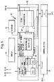
- the microcontroller 80 consists of a power supply 81 with customer-specific signal outputs, a controller board 82 which contains the microprocessor, the display 83 and the keyboard 84.
- the controller power supply 81 supplies the supply voltage for the controller board 82 and the display 84.
- the off - And input signals to the microprocessor are looped through the power supply board 81. These include e.g. Overload, ready, ultrasound on (USON), emergency stop (emergency off) and trend signals that indicate trends of a measured variable in the direction of a specified limit.
- the signals: Transformer current greater than the nominal value and high-frequency indication are not monitored by the microcontroller, but are given directly to an output. If the rated current is exceeded, the blanking of the master relay 21 in the main power supply 20 comes into action.
- the HF indication can be used by an external controller as a monitoring variable.
- the controller board 82 consists of an 8-bit controller 85, which offers analog inputs for the following information:
- a voltage signal U (IW) that is proportional to the converter current at the RF output.
- the phase detector 86 also provides a directional indication of the phase angle so that the processor knows in which direction the phase zero crossing is to be sought.
- a voltage signal that is proportional to the alternating current at the RF output is proportional to the alternating current at the RF output.
- a voltage signal that is proportional to the alternating voltage at the RF output is proportional to the alternating voltage at the RF output.
- the above-mentioned measured variables can be used individually or in groups or all to control the generator.
- the control is based on a software program that uses the various control variables after selection. This selection can be made automatically or after input by the operator.
- the impedance curve has a minimum and a maximum.
- the maximum corresponds to the parallel resonance of the converter system.
- the minimum is the series resonance.
- phase curve also shown in FIG. 6. It has a steep Transition from -90 ° to + 90 °. So a small change in frequency means a big change in phase. The phase in the area of the resonance point is very small or zero. Physically, this means that the apparent and active power share are the same.
Landscapes
- Engineering & Computer Science (AREA)
- Mechanical Engineering (AREA)
- Physics & Mathematics (AREA)
- General Physics & Mathematics (AREA)
- Apparatuses For Generation Of Mechanical Vibrations (AREA)
- Pressure Welding/Diffusion-Bonding (AREA)
- Transducers For Ultrasonic Waves (AREA)
- Inverter Devices (AREA)
Applications Claiming Priority (2)
| Application Number | Priority Date | Filing Date | Title |
|---|---|---|---|
| DE4400210A DE4400210A1 (de) | 1994-01-05 | 1994-01-05 | Verfahren und Einrichtung zum Betrieb eines Generators zur HF-Energieversorgung eines Ultraschallwandlers |
| DE4400210 | 1994-01-05 |
Publications (3)
| Publication Number | Publication Date |
|---|---|
| EP0662356A2 true EP0662356A2 (fr) | 1995-07-12 |
| EP0662356A3 EP0662356A3 (fr) | 1996-05-01 |
| EP0662356B1 EP0662356B1 (fr) | 1999-04-07 |
Family
ID=6507506
Family Applications (1)
| Application Number | Title | Priority Date | Filing Date |
|---|---|---|---|
| EP95100122A Expired - Lifetime EP0662356B1 (fr) | 1994-01-05 | 1995-01-05 | Procédé et dispositif d'entraínement d'un générateur pour l'alimentation d'énergie HF d'un transducteur à ultrason |
Country Status (8)
| Country | Link |
|---|---|
| US (1) | US5637947A (fr) |
| EP (1) | EP0662356B1 (fr) |
| JP (1) | JPH07303379A (fr) |
| KR (1) | KR950033496A (fr) |
| BR (1) | BR9500024A (fr) |
| CA (1) | CA2139472C (fr) |
| DE (2) | DE4400210A1 (fr) |
| ES (1) | ES2133590T3 (fr) |
Cited By (3)
| Publication number | Priority date | Publication date | Assignee | Title |
|---|---|---|---|---|
| FR2740572A1 (fr) * | 1995-10-27 | 1997-04-30 | Lorraine Laminage | Procede et dispositif de pilotage d'actionneurs a ultra-sons de puissance |
| EP1738836A3 (fr) * | 2005-07-01 | 2009-05-27 | Martin Walter Ultraschalltechnik AG | Procédé et dispositif de mise en marche d'un système de vibration ultrasonique |
| EP2737287B1 (fr) * | 2011-07-29 | 2021-08-11 | Herrmann Ultraschalltechnik GmbH & Co. KG | Procédé de calcul de l'amplitude de vibration d'une sonotrode |
Families Citing this family (36)
| Publication number | Priority date | Publication date | Assignee | Title |
|---|---|---|---|---|
| JP2757810B2 (ja) * | 1995-03-08 | 1998-05-25 | 日本電気株式会社 | 電源装置 |
| EP0839585A3 (fr) * | 1996-10-31 | 2000-12-27 | Eastman Kodak Company | Procédé et dispositif pour l'épreuve d'un dispositif pour l'élimination des bulles au moyen d'un combinaison transducteur-horne |
| US5954719A (en) * | 1996-12-11 | 1999-09-21 | Irvine Biomedical, Inc. | System for operating a RF ablation generator |
| DE19810509C2 (de) * | 1998-03-11 | 2000-02-10 | Fraunhofer Ges Forschung | Vorrichtung zum Schweißen mit Ultraschall |
| US6352532B1 (en) | 1999-12-14 | 2002-03-05 | Ethicon Endo-Surgery, Inc. | Active load control of ultrasonic surgical instruments |
| US6626926B2 (en) * | 2000-10-20 | 2003-09-30 | Ethicon Endo-Surgery, Inc. | Method for driving an ultrasonic system to improve acquisition of blade resonance frequency at startup |
| KR100752334B1 (ko) * | 2001-04-13 | 2007-08-29 | 주식회사 메디슨 | 초음파 영상 형성 장치용 이차원 곡면 배열 변환자 |
| US6819027B2 (en) * | 2002-03-04 | 2004-11-16 | Cepheid | Method and apparatus for controlling ultrasonic transducer |
| TWI271247B (en) * | 2003-03-21 | 2007-01-21 | Esec Trading Sa | Wire bonder |
| GB2416458B (en) * | 2004-07-20 | 2008-11-26 | Sra Dev Ltd | Ultrasonic generator system |
| US7769551B2 (en) * | 2005-01-03 | 2010-08-03 | 3M Innovative Properties Company | Method and system for determining a gap between a vibrational body and fixed point |
| US7775413B2 (en) * | 2005-01-03 | 2010-08-17 | 3M Innovative Properties Company | Cantilevered bar gap adjustment for an ultrasonic welding system |
| US7828192B2 (en) * | 2005-01-03 | 2010-11-09 | 3M Innovative Properties Company | Amplitude adjustment of an ultrasonic horn |
| US20100276061A1 (en) * | 2005-12-30 | 2010-11-04 | 3M Innovative Properties Company | Cantilevered bar gap adjustment for an ultrasonic welding system |
| US8704131B2 (en) * | 2006-03-31 | 2014-04-22 | Illinois Tool Works Inc. | Method and apparatus for pulse welding |
| DE102006020417B4 (de) * | 2006-04-26 | 2008-10-02 | Herrmann Ultraschalltechnik Gmbh & Co. Kg | Vorrichtung zum Bearbeiten von Werkstücken mittels Ultraschall |
| EP2285520B1 (fr) * | 2008-05-02 | 2019-01-02 | Sonics & Materials Inc. | Système pour empêcher des surcharges pour des applications de rivetage par ultrasons |
| DE102010004468A1 (de) * | 2010-01-13 | 2011-07-14 | Maschinenfabrik Spaichingen GmbH, 78549 | Verfahren und Vorrichtung zur Ultraschallbearbeitung |
| US8258886B2 (en) | 2010-03-30 | 2012-09-04 | Tyco Healthcare Group Lp | System and method for improved start-up of self-oscillating electro-mechanical surgical devices |
| WO2012094298A1 (fr) * | 2011-01-06 | 2012-07-12 | The Lubrizol Corporation | Mesure par ultrasons |
| US8444664B2 (en) | 2011-05-16 | 2013-05-21 | Covidien Lp | Medical ultrasound instrument with articulated jaws |
| US8662745B2 (en) | 2011-11-11 | 2014-03-04 | Covidien Lp | Methods of measuring conditions of an ultrasonic instrument |
| US9351753B2 (en) | 2012-01-30 | 2016-05-31 | Covidien Lp | Ultrasonic medical instrument with a curved waveguide |
| DE102012215993A1 (de) * | 2012-09-10 | 2014-03-13 | Weber Ultrasonics Gmbh | Ultraschallsystem, Ultraschallgenerator und Verfahren zum Betreiben eines solchen |
| CN104142426A (zh) * | 2013-05-09 | 2014-11-12 | 瑞奇外科器械(中国)有限公司 | 查找换能器谐振频率点的方法及系统 |
| DE102013225042A1 (de) | 2013-12-05 | 2015-06-11 | Branson Ultraschall Niederlassung Der Emerson Technologies Gmbh & Co. Ohg | Ultraschallschweißvorrichtung und Ultraschallschweißverfahren zur Regelung von kontinuierlichen Ultraschallschweißprozessen |
| KR101672458B1 (ko) * | 2014-09-29 | 2016-11-03 | 주식회사 코러스트 | 초음파 생성 장치 |
| US10987124B2 (en) | 2016-11-22 | 2021-04-27 | Covidien Lp | Surgical instruments and jaw members thereof |
| WO2019032232A1 (fr) * | 2017-08-09 | 2019-02-14 | Branson Ultrasonics Corporation | Commande de phase de rétroaction agile dans un système ultrasonore ayant un bloc ultrasonore |
| US20190143370A1 (en) * | 2017-11-10 | 2019-05-16 | Branson Ultrasonics Corporation | Mitigating Current At Startup Of Ultrasonics |
| US11076910B2 (en) | 2018-01-22 | 2021-08-03 | Covidien Lp | Jaw members for surgical instruments and surgical instruments incorporating the same |
| US20190299310A1 (en) * | 2018-03-30 | 2019-10-03 | Branson Ultrasonics Corporation | Contact Detection Based On Frequency In Ultrasonics |
| DE102020201540A1 (de) * | 2020-02-07 | 2021-08-12 | Sauer Gmbh | Verfahren und system zum steuern eines ultraschallgenerators einer werkzeugmaschine zur bearbeitung eines werkstücks |
| CN113787050B (zh) * | 2021-09-27 | 2023-08-18 | 韶关市洁盟超声科技有限公司 | 一种超声波输出波形可控的超声波清洗机 |
| CN114221525B (zh) * | 2021-12-16 | 2024-05-03 | 珠海格力电器股份有限公司 | 换能器输出功率的处理方法、装置以及超声波设备 |
| CN119768239A (zh) | 2022-09-05 | 2025-04-04 | 海尔曼超声波技术两合有限公司 | 借助机械超声波振荡加工工件的超声波工具和方法 |
Family Cites Families (28)
| Publication number | Priority date | Publication date | Assignee | Title |
|---|---|---|---|---|
| BE793601A (fr) * | 1972-01-03 | 1973-07-02 | Philips Nv | Generateur d'ultrasons |
| US4277710A (en) * | 1979-04-30 | 1981-07-07 | Dukane Corporation | Control circuit for piezoelectric ultrasonic generators |
| JPS5610792A (en) * | 1979-07-06 | 1981-02-03 | Taga Denki Kk | Method and circuit for driving ultrasonic-wave converter |
| DE3334066A1 (de) * | 1982-09-27 | 1984-03-29 | Branson Ultrasonics Corp., 06470 Newtown, Conn. | Mikroprozessorgesteuerter ultraschallschweissapparat |
| JPH0630734B2 (ja) * | 1983-08-05 | 1994-04-27 | 多賀電気株式会社 | 超音波変換器駆動制御方法 |
| GB2156174B (en) * | 1984-03-21 | 1988-01-27 | Plessey Co Plc | Electrical oscillator tuning arrangement |
| US4560998A (en) * | 1984-07-18 | 1985-12-24 | Tektronix, Inc. | Low voltage transformer coupled ink jet driver |
| US4864547A (en) * | 1986-05-20 | 1989-09-05 | Crestek, Inc. | Regulated ultrasonic generator |
| FR2586883B1 (fr) * | 1985-08-27 | 1994-04-01 | Nord Institut Superieur Electron | Procede et dispositif d'alimentation electrique d'un transducteur generateur de vibrations tant sonores qu'ultrasonores. |
| GB8611510D0 (en) * | 1986-05-12 | 1986-06-18 | Rawson F F H | Ultrasonic devices |
| ES2003363A6 (es) * | 1986-10-02 | 1988-11-01 | Gh Ind Sa | Perfeccionamientos en generadores de alta frecuencia para aplicaciones de calentamiento por induccion laser plasma y similares |
| EP0270819A3 (fr) * | 1986-11-07 | 1989-01-11 | Alcon Laboratories, Inc. | Commande linéaire de puissance d'un transducteur à ultrasons au moyen d'une réactance accordée |
| US4687962A (en) * | 1986-12-15 | 1987-08-18 | Baxter Travenol Laboratories, Inc. | Ultrasonic horn driving apparatus and method with active frequency tracking |
| US5001649A (en) * | 1987-04-06 | 1991-03-19 | Alcon Laboratories, Inc. | Linear power control for ultrasonic probe with tuned reactance |
| US4808948A (en) * | 1987-09-28 | 1989-02-28 | Kulicke And Soffa Indusries, Inc. | Automatic tuning system for ultrasonic generators |
| US4879528A (en) * | 1988-08-30 | 1989-11-07 | Olympus Optical Co., Ltd. | Ultrasonic oscillation circuit |
| JPH0628230Y2 (ja) * | 1989-05-30 | 1994-08-03 | スタンレー電気株式会社 | 超音波振動子の振動制御装置 |
| US4973876A (en) * | 1989-09-20 | 1990-11-27 | Branson Ultrasonics Corporation | Ultrasonic power supply |
| SU1739499A1 (ru) * | 1989-11-30 | 1992-06-07 | Казахское Научно-Производственное Объединение "Системотехника" | Устройство стабилизации амплитуды колебаний автогенератора |
| US5026387A (en) * | 1990-03-12 | 1991-06-25 | Ultracision Inc. | Method and apparatus for ultrasonic surgical cutting and hemostatis |
| EP0498936B1 (fr) * | 1991-02-15 | 1995-01-25 | Esec Sa | Procédé et dispositif de mesure de l'amplitude d'oscillation d'un transducteur d'énergie |
| JP2737420B2 (ja) * | 1991-03-04 | 1998-04-08 | 日本電気株式会社 | 超音波モータの駆動方式 |
| US5315533A (en) * | 1991-05-17 | 1994-05-24 | Best Power Technology, Inc. | Back-up uninterruptible power system |
| FR2681261B1 (fr) * | 1991-09-13 | 1995-06-09 | Suzuki Motor Co | Circuit d'excitation et de commande pour un vibreur ultrasonore. |
| DE4206584C2 (de) * | 1992-03-03 | 1994-03-10 | Fraunhofer Ges Forschung | Vorrichtung und Verfahren zum Verbinden zweier Bauteile mittels Ultraschall |
| US5170929A (en) * | 1992-05-29 | 1992-12-15 | International Business Machines Corporation | Ultrasonic adhesion/dehesion monitoring apparatus with acoustic transducer means |
| DE4233016A1 (de) * | 1992-10-01 | 1994-02-24 | Alfred Kueck | Elektrische Einrichtung für ein Ultraschallreinigungsgerät |
| US5460595A (en) * | 1993-06-01 | 1995-10-24 | Dynatronics Laser Corporation | Multi-frequency ultrasound therapy systems and methods |
-
1994
- 1994-01-05 DE DE4400210A patent/DE4400210A1/de not_active Ceased
-
1995
- 1995-01-03 CA CA002139472A patent/CA2139472C/fr not_active Expired - Fee Related
- 1995-01-04 BR BR9500024A patent/BR9500024A/pt not_active IP Right Cessation
- 1995-01-04 US US08/368,328 patent/US5637947A/en not_active Expired - Fee Related
- 1995-01-05 EP EP95100122A patent/EP0662356B1/fr not_active Expired - Lifetime
- 1995-01-05 ES ES95100122T patent/ES2133590T3/es not_active Expired - Lifetime
- 1995-01-05 DE DE59505542T patent/DE59505542D1/de not_active Expired - Fee Related
- 1995-01-05 KR KR1019950000114A patent/KR950033496A/ko not_active Withdrawn
- 1995-01-05 JP JP7000346A patent/JPH07303379A/ja active Pending
Cited By (5)
| Publication number | Priority date | Publication date | Assignee | Title |
|---|---|---|---|---|
| FR2740572A1 (fr) * | 1995-10-27 | 1997-04-30 | Lorraine Laminage | Procede et dispositif de pilotage d'actionneurs a ultra-sons de puissance |
| EP0770430A1 (fr) * | 1995-10-27 | 1997-05-02 | Sollac S.A. | Procédé et dispositif de pilotage d'actionneurs à ulta-sons de puissance |
| US5739724A (en) * | 1995-10-27 | 1998-04-14 | Sollac And Ascometal S.A. | Control of oscillator for driving power ultrasonic actuators |
| EP1738836A3 (fr) * | 2005-07-01 | 2009-05-27 | Martin Walter Ultraschalltechnik AG | Procédé et dispositif de mise en marche d'un système de vibration ultrasonique |
| EP2737287B1 (fr) * | 2011-07-29 | 2021-08-11 | Herrmann Ultraschalltechnik GmbH & Co. KG | Procédé de calcul de l'amplitude de vibration d'une sonotrode |
Also Published As
| Publication number | Publication date |
|---|---|
| BR9500024A (pt) | 1995-11-07 |
| ES2133590T3 (es) | 1999-09-16 |
| EP0662356A3 (fr) | 1996-05-01 |
| CA2139472A1 (fr) | 1995-07-06 |
| KR950033496A (ko) | 1995-12-26 |
| DE59505542D1 (de) | 1999-05-12 |
| US5637947A (en) | 1997-06-10 |
| DE4400210A1 (de) | 1995-08-10 |
| EP0662356B1 (fr) | 1999-04-07 |
| JPH07303379A (ja) | 1995-11-14 |
| CA2139472C (fr) | 2002-07-23 |
Similar Documents
| Publication | Publication Date | Title |
|---|---|---|
| EP0662356B1 (fr) | Procédé et dispositif d'entraínement d'un générateur pour l'alimentation d'énergie HF d'un transducteur à ultrason | |
| EP1386078B1 (fr) | Installation d'energie eolienne procede d'exploitation d'une installation d'energie eolienne | |
| EP2705906B1 (fr) | Système ultrasonore, générateur d'ultrasons et procédé de fonctionnement de celui-ci | |
| DE69333234T2 (de) | Schaltkreis für eine Phakoemulgator-Sonde mit Schalter-Ansteuerung | |
| DE68914272T2 (de) | Leistungsschaltung eines Generatorspannungsreglers. | |
| EP1602169A2 (fr) | Circuit d'excitation pour alimentation a decoupage | |
| EP2482442B1 (fr) | Procédé et système de commande destinés au fonctionnement d'un moteur électrique sans balais | |
| DE102010005008A1 (de) | Elektrowerkzeug | |
| DE60222325T2 (de) | Steuermittel einer Stromversorgung bei einem Magnetron | |
| EP4040640A1 (fr) | Procédé de fonctionnement d'un dispositif de transmission sans fil de l'énergie dans la direction d'un consommateur électrique au moyen d'un couplage inductif, dispositif et système | |
| DE102014219335B4 (de) | Verfahren und vorrichtung zur unterdrückung von überschwingen für leistungswandler | |
| EP0876742A1 (fr) | Procede et circuit de commande electronique pour la regulation des caracteristiques de fonctionnement de lampes a decharge | |
| EP2273646B1 (fr) | Procédé pour la compensation de puissance réactive et dispositif de production d'énergie électrique dans un réseau électrique | |
| EP2874547B1 (fr) | Dispositif et procédé de commande d'entraînement d'un système chirurgical à moteur | |
| DE112014001983T5 (de) | Motorsteuerungsvorrichtung und Motorsteuerungsverfahren | |
| EP3605832A1 (fr) | Courant de maintien adaptatif pour moteurs électriques à commutation électrique | |
| EP4255662B1 (fr) | Methode pour limiter la puissance d'un appareil de soudage | |
| EP1377135B1 (fr) | Circuit muni d'une détection d'approche de fonctionnement en mode capacitif pour alimenter une lampe à décharge | |
| EP1742516B1 (fr) | Dispositif et méthode pour alimenter au moins une lampe | |
| EP1670294B1 (fr) | Appareil et méthode pour commander des lampes à décharge | |
| EP1994805A1 (fr) | Ensemble circuit et procédé pour faire fonctionner une lampe à décharge haute pression | |
| EP1708549B1 (fr) | Ballast avec dispositif de gradation | |
| DE3224301C2 (fr) | ||
| WO1992022118A1 (fr) | Procede de circuit pour la transmission de courant continu | |
| EP4683193A1 (fr) | Commande d'un convertisseur avec spécification améliorée de la fréquence d'impulsion |
Legal Events
| Date | Code | Title | Description |
|---|---|---|---|
| PUAI | Public reference made under article 153(3) epc to a published international application that has entered the european phase |
Free format text: ORIGINAL CODE: 0009012 |
|
| AK | Designated contracting states |
Kind code of ref document: A2 Designated state(s): CH DE ES FR GB IT LI |
|
| PUAL | Search report despatched |
Free format text: ORIGINAL CODE: 0009013 |
|
| AK | Designated contracting states |
Kind code of ref document: A3 Designated state(s): CH DE ES FR GB IT LI |
|
| 17P | Request for examination filed |
Effective date: 19961031 |
|
| 17Q | First examination report despatched |
Effective date: 19970604 |
|
| GRAG | Despatch of communication of intention to grant |
Free format text: ORIGINAL CODE: EPIDOS AGRA |
|
| GRAG | Despatch of communication of intention to grant |
Free format text: ORIGINAL CODE: EPIDOS AGRA |
|
| GRAH | Despatch of communication of intention to grant a patent |
Free format text: ORIGINAL CODE: EPIDOS IGRA |
|
| GRAH | Despatch of communication of intention to grant a patent |
Free format text: ORIGINAL CODE: EPIDOS IGRA |
|
| GRAA | (expected) grant |
Free format text: ORIGINAL CODE: 0009210 |
|
| AK | Designated contracting states |
Kind code of ref document: B1 Designated state(s): CH DE ES FR GB IT LI |
|
| REG | Reference to a national code |
Ref country code: CH Ref legal event code: EP |
|
| REF | Corresponds to: |
Ref document number: 59505542 Country of ref document: DE Date of ref document: 19990512 |
|
| GBT | Gb: translation of ep patent filed (gb section 77(6)(a)/1977) |
Effective date: 19990610 |
|
| ET | Fr: translation filed | ||
| REG | Reference to a national code |
Ref country code: CH Ref legal event code: NV Representative=s name: ISLER & PEDRAZZINI AG |
|
| REG | Reference to a national code |
Ref country code: ES Ref legal event code: FG2A Ref document number: 2133590 Country of ref document: ES Kind code of ref document: T3 |
|
| PLBE | No opposition filed within time limit |
Free format text: ORIGINAL CODE: 0009261 |
|
| STAA | Information on the status of an ep patent application or granted ep patent |
Free format text: STATUS: NO OPPOSITION FILED WITHIN TIME LIMIT |
|
| 26N | No opposition filed | ||
| REG | Reference to a national code |
Ref country code: GB Ref legal event code: IF02 |
|
| PGFP | Annual fee paid to national office [announced via postgrant information from national office to epo] |
Ref country code: FR Payment date: 20021227 Year of fee payment: 9 |
|
| PGFP | Annual fee paid to national office [announced via postgrant information from national office to epo] |
Ref country code: GB Payment date: 20021231 Year of fee payment: 9 |
|
| PGFP | Annual fee paid to national office [announced via postgrant information from national office to epo] |
Ref country code: DE Payment date: 20030110 Year of fee payment: 9 |
|
| PGFP | Annual fee paid to national office [announced via postgrant information from national office to epo] |
Ref country code: ES Payment date: 20030114 Year of fee payment: 9 |
|
| PGFP | Annual fee paid to national office [announced via postgrant information from national office to epo] |
Ref country code: CH Payment date: 20030129 Year of fee payment: 9 |
|
| PG25 | Lapsed in a contracting state [announced via postgrant information from national office to epo] |
Ref country code: GB Free format text: LAPSE BECAUSE OF NON-PAYMENT OF DUE FEES Effective date: 20040105 |
|
| PG25 | Lapsed in a contracting state [announced via postgrant information from national office to epo] |
Ref country code: ES Free format text: LAPSE BECAUSE OF NON-PAYMENT OF DUE FEES Effective date: 20040107 |
|
| PG25 | Lapsed in a contracting state [announced via postgrant information from national office to epo] |
Ref country code: LI Free format text: LAPSE BECAUSE OF NON-PAYMENT OF DUE FEES Effective date: 20040131 Ref country code: CH Free format text: LAPSE BECAUSE OF NON-PAYMENT OF DUE FEES Effective date: 20040131 |
|
| PG25 | Lapsed in a contracting state [announced via postgrant information from national office to epo] |
Ref country code: DE Free format text: LAPSE BECAUSE OF NON-PAYMENT OF DUE FEES Effective date: 20040803 |
|
| GBPC | Gb: european patent ceased through non-payment of renewal fee |
Effective date: 20040105 |
|
| REG | Reference to a national code |
Ref country code: CH Ref legal event code: PL |
|
| PG25 | Lapsed in a contracting state [announced via postgrant information from national office to epo] |
Ref country code: FR Free format text: LAPSE BECAUSE OF NON-PAYMENT OF DUE FEES Effective date: 20040930 |
|
| REG | Reference to a national code |
Ref country code: FR Ref legal event code: ST |
|
| PG25 | Lapsed in a contracting state [announced via postgrant information from national office to epo] |
Ref country code: IT Free format text: LAPSE BECAUSE OF NON-PAYMENT OF DUE FEES;WARNING: LAPSES OF ITALIAN PATENTS WITH EFFECTIVE DATE BEFORE 2007 MAY HAVE OCCURRED AT ANY TIME BEFORE 2007. THE CORRECT EFFECTIVE DATE MAY BE DIFFERENT FROM THE ONE RECORDED. Effective date: 20050105 |
|
| REG | Reference to a national code |
Ref country code: ES Ref legal event code: FD2A Effective date: 20040107 |