EP0663115B1 - Transmision de c.c. a haute tension - Google Patents
Transmision de c.c. a haute tension Download PDFInfo
- Publication number
- EP0663115B1 EP0663115B1 EP94922397A EP94922397A EP0663115B1 EP 0663115 B1 EP0663115 B1 EP 0663115B1 EP 94922397 A EP94922397 A EP 94922397A EP 94922397 A EP94922397 A EP 94922397A EP 0663115 B1 EP0663115 B1 EP 0663115B1
- Authority
- EP
- European Patent Office
- Prior art keywords
- converter
- alternating
- converters
- hvdc transmission
- transmission according
- Prior art date
- Legal status (The legal status is an assumption and is not a legal conclusion. Google has not performed a legal analysis and makes no representation as to the accuracy of the status listed.)
- Expired - Lifetime
Links
Images





Classifications
-
- H—ELECTRICITY
- H02—GENERATION; CONVERSION OR DISTRIBUTION OF ELECTRIC POWER
- H02J—ELECTRIC POWER NETWORKS; CIRCUIT ARRANGEMENTS OR SYSTEMS FOR SUPPLYING OR DISTRIBUTING ELECTRIC POWER; SYSTEMS FOR STORING ELECTRIC ENERGY
- H02J3/00—Circuit arrangements for AC mains or AC distribution networks
- H02J3/36—Arrangements for transfer of electric power between AC networks via high-voltage DC [HVDC] links; Arrangements for transfer of electric power between generators and networks via HVDC links
-
- Y—GENERAL TAGGING OF NEW TECHNOLOGICAL DEVELOPMENTS; GENERAL TAGGING OF CROSS-SECTIONAL TECHNOLOGIES SPANNING OVER SEVERAL SECTIONS OF THE IPC; TECHNICAL SUBJECTS COVERED BY FORMER USPC CROSS-REFERENCE ART COLLECTIONS [XRACs] AND DIGESTS
- Y02—TECHNOLOGIES OR APPLICATIONS FOR MITIGATION OR ADAPTATION AGAINST CLIMATE CHANGE
- Y02E—REDUCTION OF GREENHOUSE GAS [GHG] EMISSIONS, RELATED TO ENERGY GENERATION, TRANSMISSION OR DISTRIBUTION
- Y02E60/00—Enabling technologies; Technologies with a potential or indirect contribution to GHG emissions mitigation
- Y02E60/60—Arrangements for transfer of electric power between AC networks or generators via a high voltage DC link [HVCD]
Definitions
- the present invention relates to an HVDC transmission comprising at least two converters, each converter being connected between an alternating-voltage network and a direct-current link common to the converters, at least a first converter being connected to its alternating-voltage network without the use of any separate winding transformer.
- HVDC transmission relates to an electric plant or equipment for power transmission by means of high-voltage direct current.
- the concept comprises two main types of plants.
- the first of these types consists of plants adapted for power transmission between two or more converter stations, which are located in spaced relationship to each other and which are interconnected by means of direct-current carrying cables or overhead lines.
- the second type consists of so-called back-to-back connections, in which two converters arranged in the same converter station are each connected to their own alternating-voltage network and are interconnected on their d.c. sides and adapted for controllable power transmission between the alternating-voltage networks.
- the d.c. link In the first type of plants, the d.c. link consists of the cable/cables or lines which connect the d.c. sides of the converter stations. In the second type of plants, the d.c. link generally consists of only one pair of busbars in the station. However, in both cases the d.c. link comprises, in a known manner, certain devices for smoothing and filtering of the direct current, for current and voltage measurement, for protection against overvoltages, etc.
- a converter which is connected to its alternating-voltage network "without the use of any separate winding transformer” means that the converter is connected to the alternating-voltage network in some other way than by means of an separate winding transformer.
- a converter which is connected without the use of any separate winding transformer may have its alternating-voltage terminals galvanically connected to the alternating-voltage network, directly or via an autotransformer, and possibly via inductors for current limitation.
- a converter which is connected without the use of any separate winding transformer may have its alternating-voltage terminals connected to the alternating-voltage network via series capacitors.
- the concept "transformerless" connection is used in this application in the event that no transformer of any kind, thus neither a separate winding transformer nor an auto transformer, is used for connection of a converter to its alternating voltage terminal.
- the converter may have its alternating-voltage terminals galvanically connected to the alternating-voltage network, or via series capacitors.
- each one of the converters usually consists of two series-connected six-pulse bridges.
- Each bridge is connected to the alternating-voltage network via a separate winding transformer.
- the transformers of the bridges (or the valve windings of a common transformer) are designed with different connections (usually star and delta connections, respectively) in such a way that the alternating voltages of the bridges are subjected to a 30° phase shift and the converter hence becomes a twelve-pulse converter.
- HVDC transmissions of this kind are amply described in the literature, for example in Erich Uhlmann: "Power Transmission by Direct Current", Springer-Verlag Berlin Heidelberg New York 1975 (see, e.g., Fig. 2.7, p. 15, or Fig. B.1, p. 187).
- the converter bridges are connected to the alternating-voltage network via transformers, a possibility of technical-economic optimization of the direct voltage and direct current levels of the transmission is obtained. Since the converter bridges are connected to the alternating-voltage network via separate winding transformers, a galvanic separation is obtained between the bridges and the alternating-voltage network. This means that, in the manner described above, two converter bridges can be d.c.-series-connected and thus that higher resultant pulse numbers and a reduction of the harmonic content (theoretically an elimination of the lowest harmonics) can be obtained. In this way, the amount of filter equipment can be reduced, which is important since the cost of the filter equipment constitutes an important part of the total cost of a typical HVDC plant.
- the galvanic separation also means that a converter cannot generate a direct current in the alternating-voltage network, which would involve a risk of certain disturbances, such as transformer saturation.
- the direct-voltage level of the plant is determined by the voltage in the alternating-voltage networks, which means that there is no possibility of optimization of the d.c. link and the converters with respect to voltage and current.
- a transformerless HVDC plant is limited to six-pulse operation of the converters, which results in the existence of harmonics of low orders (5 and 7), which necessitate considerably more costly equipment for harmonic filtering.
- third tone currents (harmonic currents of the orders 3, 9, 15, 21 ...) are generated on the d.c. side of a converter. These currents flow out into the alternating-voltage network of the converter.
- the currents are of zero-sequence type and give rise to considerable drawbacks in the form of telecommunication disturbance and voltage distortion in the network.
- the voltage distortion becomes such a serious disadvantage that the transformerless connection cannot be used without taking special steps.
- filters for the above-mentioned third-tone currents can thus be arranged on the a.c. side of a converter.
- the filter is large and expensive, and it has proved difficult to avoid resonance effects between the filter and the alternating-voltage network.
- a third-tone filter can be arranged in the form of a suppression filter on the d.c. side of the converter. Also in this case, the dimensions and costs of the filter equipment are high, and a considerable risk of resonance effects arises.
- the invention aims to provide an HVDC transmission which is simpler and less expensive than hitherto used transmissions while at the same time, by reducing or completely avoiding the above-described network disturbances on the alternating-voltage side (in the form of telecommunication disturbances and voltage distortion), it can be used also with weak alternating-voltage networks.
- a converter SR has the d.c. supply lines DL1 and DL2 as well as the a.c. supply lines VLR, VLS and VLT.
- the currents, flowing in the d.c. supply lines at a certain moment, have -the instantaneous values il and i2, respectively. Both currents are defined by their positive directions out from the converter.
- the pole mode current on the alternating-voltage side of the converter is then (i1-i2)/2.
- the ground mode current on the direct-voltage side of the converter is (i1+i2)/2.
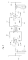
- Figure 2 shows in the form of a single-line diagram a back-to-back connection according to the invention. It is intended for controllable power transmission between two three-phase electric a.c. power networks N1 and N2. It comprises two controllable high-voltage converters SR1 and SR2, arranged in one and the same converter station.
- the a.c. supply conductors VL1 and VL2 of the converters are connected to the respective alternating-voltage networks N1 and N2 via current-limiting inductors IL1 and IL2. Further, on their a.c. side each converter has a schematically shown harmonic filter, F1 and F2, respectively.
- terminals LL1P, LL1N and LL2P, LL2N, respectively, of the converters are interconnected via conductors L1 and L2, which consist of busbars or the like in the converter station.
- a smoothing inductor IG for the direct current is arranged in conventional manner.
- the plant is provided with an inductor IB for blocking of the ground mode current.
- This inductor has two windings IB1 and IB2, which are each connected into a respective one of the two d.c. conductors L1 and L2, and which have the winding directions marked in the figure.
- the inductor is designed such that its two windings are magnetically well coupled to each other and such that the windings are symmetrical in relation to each other. In this way, the inductor will have a high impedance to ground mode currents, both to fundamental and to harmonic components, and, in principle, a low impedance to pole mode currents.
- the inductor IB will effectively block the ground mode currents and in this way greatly reduce the zero-sequence currents on the a.c. sides of the converters and hence the initially mentioned disturbances which these currents cause in the alternating-voltage network.
- This makes it possible to use a transformerless HVDC transmission for connection not only to very strong alternating-voltage networks but also to weaker networks.
- FIG 3 shows the main circuit of the converter SR1 in the back-to-back connection according to Figure 2.
- the converter is a converter of the same kind as used at present in HVDC transmissions. It is a six-pulse line-commutated phase-angle controlled thyristor converter with the valves TY1 - TY6. Each valve consists of a plurality of series-connected thyristors with parallel-connected damping circuits and overvoltage protection.
- the converter has the d.c. connections LL1P and LL1N and the a.c. connections VL1R, VL1S, VL1T.
- the converter SR2 is designed in the same way.
- the current-limiting inductors IL1 and IL2 replace the impedance of the converter transformer of conventional HVDC transmissions.
- the inductors may suitably be designed as air inductors and are given an inductance so adapted that the inductors limit the valve currents to harmless values in connection with the types of faults which may occur, for example short circuit or ground fault.
- Figure 4 shows an example of the design of one phase F1R in the filter circuit F1 in the back-to-back connection according to Figure 2. It is connected to the a.c. conductor LR between the network N1 and the converter SR1.
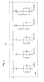
- the filter circuit consists of double-tuned band-pass filters for the tones 5 and 7 (BP5/7), 11 and 13 (BP11/13) and the tones 17 and 19 (BP17/19), and double-tuned high-pass filters for the tones 24 and 42 (HP24/42) and for the tones 30 and 36 (HP30/36).
- the high-pass filters are suitably designed so as to provide sufficient damping also for the tones of the orders 47 and 49.
- Figures 5a and 5b show an example of the design of the blocking inductor, in which both of these requirements are fulfilled.
- Figure 5a shows a section through the inductor in th.e pla.ne which contains the axes of rotational symmetry of the windings.
- Figure 5b shows the inductor as viewed in the direction of the axes of rotational symmetry.
- the inductor has an iron core IB3.
- the windings IB1 and IB2 each consist of two series-connected winding halves.
- On a first core leg one half IB1A of the winding IB1 and one half IB2A of the winding IB2 are arranged with the winding IB1A outside the winding IB2A.
- On a second core leg the second half IB1B of the winding IB1 and the second half IB2B of the winding IB2 are arranged with the winding IB2B outside the winding IB1B. Since the winding halves on each core leg are arranged close to each other, a good magnetic coupling is obtained between the windings.
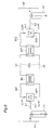
- FIG. 6 schematically shows an HVDC transmisson consisting of two geographically separated converter stations with converters SR1 and SR2, which are interconnected through a line DCL with the conductors LA and LB.
- the line may consist of an overhead line or of a cable disposed in the ground or in water, or of a combination thereof.
- Each station is designed in the manner shown in Figure 2 and its components have the same designations as in Figure 2. In this case, however, as opposed to what is the case in the plant shown in Figure 2, each station is provided with a blocking inductor, IBI and IBII, respectively.
- each station has a smoothing inductor, IGI and IGII, respectively.
- Figure 7 shows an HVDC transmission according to the invention, which substantially corresponds to the one shown in Figure 6, but in which the converters have been connected to their alternating-voltage networks via series capacitors C1 and C2, respectively.
- the series capacitors serve as direct-voltage barriers, and hence they make possible grounding of the direct-voltage side of each converter at one point.
- the mutual inductances IBI and IBII, respectively here also block fundamental component currents of ground mode type, currents which would otherwise arise and make conversion impossible.
- the figure shows how one pole of each converter is grounded, whereby the line between the converter stations may consist of one single conductor LA. The direct current return takes place through ground.
- Figure 7 thus shows a monopolar HVDC transmission.
- FIG. 8 One of the two converter stations in such a transmission is shown in Figure 8. It has two converters, SR1 and SR2. Each one of them is connected to the network N1 via a series capacitor, C1A and C1B, respectively, and a current-limiting inductor, IL1A and IL1B, respectively.
- Filter equipment F1 common to the converters, for harmonic filtering is connected to the alternating-voltage side of the converters.
- Each converter is provided with a blocking inductor, IBIA and IBIB, respectively, designed in the manner described above, and with a smoothing inductor, IGA and IGB, respectively.
- the station has a ground electrode GA, which is connected to the station by a ground line LG.
- the converter SR1A has one of its direct-voltage connections connected to one conductor LA of the transmission line via one of the windings of the inductor IBIA and the other direct-voltage connection connected to the ground line LG via the other winding of the inductor.
- the converter SR1B has one of its direct-voltage connections connected to the other conductor LAB of the transmission line via one of the windings of the inductor IBIB and the other direct-voltage connection connected to the ground line LG via the other winding of the inductor.
- a converter may be connected to its alternating-voltage network via an autotransformer.
- an autotransformer Such an embodiment offers the advantages that the current and voltage levels of the d.c. link and the converter can be chosen independently of the voltage of the alternating-voltage network, that therefore the transmission can be used for power transmission between alternating-voltage networks with different voltages, that the current-limiting inductors described above (e.g. IL1 in Fig. 2) may become superfluous, and that a tap changer of the transformer can be used to take up changes in the ratio of the direct voltage of the converter to the voltage of the alternating-voltage network, which provides a possibility of working with more optimal control angles of the converter from the reactive power point of view. Since autotransformers are considerably less expensive than separate winding transformers, also in this case a considerable cost saving is obtained compared with conventional HVDC transmissions with separate winding transformers.
- the converters at both ends of a d.c. link may be connected to their alternating-voltage networks via autotransformers, or the converter at one end of the link only, in which case the converter at the other end of the link is either transformerless or connected to its alternating-voltage network via a separate winding transformer.
- one of the converters of a transmission may be connected to its alternating-voltage network via a separate winding transformer.
- the converter at the other end of the link may thereby either be transformerless or also be connected via an autotransformer.
- the tap changer of the full transformer can thereby be utilized to take up variations in the voltage of the alternating-voltage network and the reactive power consumption thus be kept low, the d.c. link and the converters can be optimized independently of the voltage of the alternating-voltage network, and for the converter which is connected while using a separate winding transformer, no mutual inductor is needed for blocking the effect on the alternating-voltage network exerted by the link.
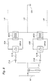
- FIG. 9 shows an alternative way of balancing the direct current.
- a transformerless converter bridge SRM main bridge
- the main bridge SRM is connected to the three-phase network N1 via a current-limiting inductor IL.
- the auxiliary bridges are connected to the network via the Y/A-connected separate winding transformers TR1 and TR2, respectively.
- the d.c. supply lines of the main bridge are connected to a mutual inductor IB in the same way as described above.
- the auxiliary bridges may have a considerably lower rated power than the main bridge.
- the auxiliary bridges are preferably controlled in such a way that the direct currents in the two d.c. lines L1 and L2 of the converter station are always maintained as equal as possible.
- the separate winding transformers of the auxiliary bridges are provided with tap changers with a wide control range, these tap changers can be utilized for compensating for variations in the alternating voltage of the network, however, at the expense of the 5th and 7th tone elimination.
- separate smoothing inductors for example IG in Figure 2
- a smoothing inductor can be obtained by designing the mutual inductance in a suitable way.
- the mutual inductor has an impedance to pole mode currents which is low, and which is zero if the mutual inductor is ideal.
- this inductor By designing this inductor with a suitably adapted leakage inductance, it can be caused to provide the desired smoothing of the direct current, and a separate smoothing inductor can then be avoided.
- an HVDC transmission according to the invention has a transformerless connection of the converter at one end of the d.c. link and a converter connection via a transformer, provided with a tap changer, at the other end of the link, it is suitable to allow the first-mentioned converter to work with a fixed control angle so chosen that the reactive power consumption is minimized, whereby variations in the ratio of the voltages of the alternating-voltage networks are taken up by the tap changer.
Landscapes
- Engineering & Computer Science (AREA)
- Power Engineering (AREA)
- Cable Transmission Systems, Equalization Of Radio And Reduction Of Echo (AREA)
- Supply And Distribution Of Alternating Current (AREA)
- Ac-Ac Conversion (AREA)
- Rectifiers (AREA)
Claims (13)
- Dispositif de transmission à courant continu à haute tension (HVDC) comportant au moins deux convertisseurs (SR1, SR2), dans lequel chaque convertisseur est connecté entre un réseau (N1, N2) à tension alternative et une liaison (L1,L2) à courant continu qui sont communs aux convertisseurs, et dans lequel au moins un premier convertisseur est connecté à son réseau à tension alternative sans l'utilisation d'un transformateur à enroulement distinct, caractérisé en ce que le dispositif de transmission comporte au moins une inductance (IB) mutuelle prévue sur le côté à courant continu du premier convertisseur, l'inductance mutuelle ayant deux enroulements (IB1, IB2) qui sont chacun connectés à l'une respective des lignes d'alimentation en courant continu du premier convertisseur, les enroulements ayant un bon couplage magnétique l'un avec l'autre et un grand degré de symétrie, présentant ainsi une impédance élevée à des courants en mode de terre.
- Dispositif de transmission HVDC suivant la revendication 1, qui est conçu en comportant au moins deux convertisseurs (SR1, SR2) connectés en opposition, caractérisé en ce que les deux convertisseurs desdits au moins deux convertisseurs sont connectés à leur réseau à tension alternative sans l'utilisation de transformateur à enroulement distinct, et en ce que ladite au moins une inductance (IB) mutuelle, commune aux convertisseurs, est prévue dans la connexion (L1,L2) à courant continu entre les convertisseurs.
- Dispositif de transmission HVDC suivant la revendication 1, qui comporte une ligne (DCL) à courant continu qui connecte lesdits au moins deux convertisseurs (SR1, SR2), qui sont géographiquement séparés l'un de l'autre, caractérisé en ce que chaque convertisseur parmi lesdits au moins deux convertisseurs est connecté à son réseau à tension alternative sans l'utilisation d'un transformateur à enroulement distinct, et est associé à ladite au moins une inductance (IBI,IBII) mutuelle connectée dans les côtés à courant continu des convertisseurs.
- Dispositif de transmission HVDC suivant l'une quelconque des revendications précédentes, caractérisé en ce qu'au moins l'un desdits au moins deux convertisseurs est connecté à son réseau à tension alternative par l'intermédiaire de condensateurs (C1,C2) en série prévus dans les lignes d'alimentation en courant alternatif du convertisseur.
- Dispositif de transmission HVDC suivant la revendication 4, conçu en tant que dispositif de transmission bipolaire et comportant au moins un poste de convertisseur, chaque convertisseur parmi lesdits au moins deux convertisseurs (SR1A, SR1B) étant connecté en courant continu entre l'un des conducteurs des deux conducteurs (LA, LB) polaires du dispositif de transmission et une ligne (LG) de terre commune, caractérisé en ce que chacun desdits au moins deux convertisseurs du poste est connecté au réseau (N1) à tension alternative du poste par l'intermédiaire de condensateurs (C1A,C1B) en série, prévus dans les lignes d'alimentation en courant alternatif des convertisseurs.
- Dispositif de transmission HVDC suivant la revendication 5, caractérisé en ce que chacun desdits au moins deux convertisseurs dudit au moins un poste de convertisseur est associé à une inductance (IBIA,IBIB) mutuelle, qui a l'un de ses enroulements connectés dans le conducteur (par exemple LA) polaire connecté à son convertisseur associé, et son autre enroulement connecté dans le trajet de courant entre son convertisseur associé et la ligne (LG) de terre commune.
- Dispositif de transmission HVDC suivant la revendication 1, 3 ou 4, lorsque la revendication 4 dépend de la revendication 1 ou 3, caractérisé en ce qu'il comporte un poste de convertisseur comportant un premier pont (SRM) qui est connecté, sans utilisation d'un transformateur à enroulement distinct, à son réseau (N1) à tension alternative et qui est connecté en série en courant continu à un second pont (SRA1) qui par l'intermédiaire d'un premier transformateur (TR1) à enroulement distinct est connecté au réseau (N1) à tension alternative.
- Dispositif de transmission HVDC suivant la revendication 5 ou 6, lorsque la revendication 4 dépend de la revendication 1 ou 3, caractérisé en ce que le poste de convertisseur comporte un premier pont (SRM) qui est connecté, sans l'utilisation d'un transformateur à enroulement distinct, à son réseau (N1) à tension alternative et qui est connecté en série en courant continu à un second pont (SRA1), qui par l'intermédiaire d'un premier transformateur (TR1) à enroulement distinct est connecté au réseau (N1) à tension alternative.
- Dispositif de transmission HVDC suivant la revendication 7 ou 8, caractérisé en ce que le second pont (SRA1) a l'une de ses lignes d'alimentation en courant continu qui est reliée au premier pont (SRM) par l'intermédiaire d'un enroulement de ladite au moins une inductance (IB) mutuelle et son autre conducteur à courant continu qui est connecté à un premier conducteur (L1) de la liaison à courant continu, en ce que le poste de convertisseur comporte un troisième pont (SRA2) qui a l'une de ses lignes d'alimentation en courant continu qui est connecté au premier (SRM) par l'intermédiaire d'un second enroulement de ladite au moins une inductance mutuelle et son autre conducteur à courant continu qui est connecté à un second conducteur (L2) de la liaison à courant continu, et en ce que le troisième pont (SRA2) est connecté au réseau (N1) à tension alternative par l'intermédiaire d'un second transformateur (TR2) distinct à enroulement.
- Dispositif de transmission HVDC suivant la revendication 9, caractérisé en ce que les transformateurs à enroulement distinct des deuxième et troisième ponts sont connectés en Y/Δ.
- Dispositif de transmission HVDC suivant la revendication 9, caractérisé en ce que le deuxième et le troisième pont sont conçus pour des puissances nominales plus faibles que le premier pont ne l'est.
- Dispositif de transmission HVDC suivant l'une quelconque des revendications précédentes, caractérisé en ce qu'une réactance (par exemple IL1) à limitation de courant est prévue dans les lignes d'alimentation en courant alternatif allant vers le premier convertisseur (SR1).
- Dispositif de transmission HVDC suivant l'une quelconque des revendications précédentes, dans lequel chacun desdits au moins deux convertisseurs (SR1,SR2) est muni de son côté à tension alternative de circuits (F1,F2) formant filtres harmoniques adaptés pour filtrer des harmoniques d'ordre 6m+1, où m est un entier positif, caractérisé en ce que les circuits filtres du premier convertisseur comportent des filtres pour des harmoniques des ordres 5 et 7.
Applications Claiming Priority (3)
| Application Number | Priority Date | Filing Date | Title |
|---|---|---|---|
| US08/101,072 US5414612A (en) | 1993-08-03 | 1993-08-03 | HVDC transmission with a converter connected between an AC voltage and a DC link common to the converters |
| US101072 | 1993-08-03 | ||
| PCT/SE1994/000649 WO1995004395A1 (fr) | 1993-08-03 | 1994-06-30 | Transmision de c.c. a haute tension |
Publications (2)
| Publication Number | Publication Date |
|---|---|
| EP0663115A1 EP0663115A1 (fr) | 1995-07-19 |
| EP0663115B1 true EP0663115B1 (fr) | 1998-08-19 |
Family
ID=22282935
Family Applications (1)
| Application Number | Title | Priority Date | Filing Date |
|---|---|---|---|
| EP94922397A Expired - Lifetime EP0663115B1 (fr) | 1993-08-03 | 1994-06-30 | Transmision de c.c. a haute tension |
Country Status (7)
| Country | Link |
|---|---|
| US (1) | US5414612A (fr) |
| EP (1) | EP0663115B1 (fr) |
| JP (1) | JP2002509686A (fr) |
| CN (1) | CN1042476C (fr) |
| DE (1) | DE69412582T2 (fr) |
| NO (1) | NO308438B1 (fr) |
| WO (1) | WO1995004395A1 (fr) |
Families Citing this family (28)
| Publication number | Priority date | Publication date | Assignee | Title |
|---|---|---|---|---|
| JP3265398B2 (ja) * | 1992-01-30 | 2002-03-11 | 株式会社日立製作所 | 直流送電装置の制御装置 |
| SE502858C2 (sv) * | 1994-07-04 | 1996-02-05 | Asea Brown Boveri | HVDC-överföring med fulltransformatorlös anslutning av strömriktaren till sitt växelspänningsnät |
| SE9403209L (sv) * | 1994-09-23 | 1996-03-24 | Asea Brown Boveri | Seriekompenserad strömriktarstation |
| SE503374C2 (sv) * | 1994-11-15 | 1996-06-03 | Asea Brown Boveri | Förfarande och anordning för styrning av en i en anläggning för överföring av högspänd likström ingående seriekompenserad strömriktarstation |
| SE9701060L (sv) * | 1997-03-24 | 1998-03-04 | Asea Brown Boveri | Anläggning för överföring av elektrisk effekt |
| SE524384C2 (sv) * | 1997-03-24 | 2004-08-03 | Abb Ab | Anläggning för överföring av elektrisk effekt |
| SE510353C2 (sv) * | 1997-06-12 | 1999-05-17 | Asea Brown Boveri | Anläggning för högspänd likström innehållande dubbelriktat styrda tyristorer |
| US6288915B1 (en) * | 1997-12-23 | 2001-09-11 | Asea Brown Boveri Ag | Converter circuit arrangement having a DC intermediate circuit |
| US6154378A (en) * | 1998-04-29 | 2000-11-28 | Lockheed Martin Corporation | Polyphase inverter with neutral-leg inductor |
| SE515105C2 (sv) * | 1998-12-18 | 2001-06-11 | Abb Ab | Förfarande och anordning för lokalisering av en kabel i en likströmsförbindelse |
| DE10238521B4 (de) * | 2002-08-16 | 2006-01-19 | Siemens Ag | Wicklungsanordnung |
| SE525546C2 (sv) * | 2002-08-16 | 2005-03-08 | Abb Ab | Anläggning för överföring av elektrisk effekt samt ett förfarande för drift av en sådan anläggning |
| SE525006C2 (sv) * | 2002-11-13 | 2004-11-09 | Abb Ab | Hjälpkraftförsörjning |
| FR2864372A1 (fr) * | 2003-12-19 | 2005-06-24 | Hispano Suiza Sa | Convertisseur 12 alternances comportant une self de filtrage integre au redresseur |
| DE102005012371A1 (de) | 2005-03-09 | 2006-09-14 | Siemens Ag | Zwölfpuls-Hochspannungsgleichstromübertagung |
| US8044297B2 (en) * | 2005-09-19 | 2011-10-25 | Abb Technology Ltd. | Ground electrode |
| US8441817B2 (en) * | 2005-12-21 | 2013-05-14 | Abb Technology Ltd. | HVDC system including switching arrangements to switch current flow direction |
| US8471416B2 (en) * | 2008-05-29 | 2013-06-25 | Lionel O. Barthold | In situ reconstruction of high voltage electric power lines |
| WO2011127984A1 (fr) * | 2010-04-15 | 2011-10-20 | Abb Research Ltd | Convertisseur électrique modulaire à niveaux multiples avec filtre de diminution des harmoniques et de blocage de la composante continue |
| EP2559143B1 (fr) * | 2010-04-15 | 2014-01-01 | ABB Research LTD | Convertisseur multi-niveaux modulaire avec filtre pour deuxième et troisième harmoniques |
| WO2011127982A1 (fr) * | 2010-04-15 | 2011-10-20 | Abb Research Ltd | Inductance de lissage de mode commun destinée à des lignes de transmission de courant continu |
| WO2012003857A1 (fr) * | 2010-07-05 | 2012-01-12 | Abb Research Ltd | Agencement d'interfaçage entre systèmes à courant alternatif et continu |
| US9866178B2 (en) * | 2011-02-24 | 2018-01-09 | Dsp Group Ltd. | Radio frequency circuitr having an integrated harmonic filter and a radio frequency circuit having transistors of different threshold voltages |
| CN102355765A (zh) * | 2011-07-15 | 2012-02-15 | 唐德中 | 市电直接整流、高功率因数大节能的led灯电子线路 |
| WO2013044940A1 (fr) * | 2011-09-27 | 2013-04-04 | Abb Research Ltd | Borne vsc-hvdc sans transformateur complet et doté d'un condensateur monté en série |
| CN104160572B (zh) | 2012-03-01 | 2017-03-01 | 阿尔斯通技术有限公司 | 控制电路 |
| ES2586030T3 (es) * | 2012-06-19 | 2016-10-11 | Siemens Aktiengesellschaft | Acople o desacople de una potencia en un ramal de un nodo de una red de corriente continua mediante una fuente de tensión conectada en serie |
| CN109075555B (zh) * | 2016-03-17 | 2021-02-05 | Abb电网瑞士股份公司 | 电流限制装置及包括这种电流限制装置的高压直流装置和高压电力系统 |
Family Cites Families (5)
| Publication number | Priority date | Publication date | Assignee | Title |
|---|---|---|---|---|
| US2419464A (en) * | 1944-06-12 | 1947-04-22 | Gen Electric | Electronic power conversion apparatus |
| DE3305225A1 (de) * | 1983-02-16 | 1984-08-16 | BBC Aktiengesellschaft Brown, Boveri & Cie., Baden, Aargau | Hgue-kraftwerkstation in blockschaltung |
| DE3326947A1 (de) * | 1983-07-22 | 1985-02-07 | Licentia Patent-Verwaltungs-Gmbh, 6000 Frankfurt | Verfahren und schaltungsanordnung zum betrieb einer hochspannungs-gleichstrom-verbindung zwischen zwei wechselspannungsnetzen |
| CA1233198A (fr) * | 1984-03-01 | 1988-02-23 | Helmut Neupauer | Methode et appareil pour faire fonctionner un systeme de transmission a courant continu a haute tension avec commande automatique des convertisseurs |
| FI890004A7 (fi) * | 1988-08-03 | 1990-02-04 | Siemens Ag | Foerfarande foer att undvika vaexelriktarlaosning vid en till naetet aotermatande stroemriktare av en naetsidig reverseringsstroemriktare av en spaenningsmellankrets-omriktare vid dynamisk spaenningssaenkning och kopplingsanordning foer genomfoerande av foerfarandet. |
-
1993
- 1993-08-03 US US08/101,072 patent/US5414612A/en not_active Expired - Lifetime
-
1994
- 1994-06-30 JP JP50576495A patent/JP2002509686A/ja not_active Ceased
- 1994-06-30 WO PCT/SE1994/000649 patent/WO1995004395A1/fr not_active Ceased
- 1994-06-30 EP EP94922397A patent/EP0663115B1/fr not_active Expired - Lifetime
- 1994-06-30 CN CN94190552A patent/CN1042476C/zh not_active Expired - Lifetime
- 1994-06-30 DE DE69412582T patent/DE69412582T2/de not_active Expired - Lifetime
-
1995
- 1995-03-31 NO NO951260A patent/NO308438B1/no not_active IP Right Cessation
Also Published As
| Publication number | Publication date |
|---|---|
| DE69412582D1 (de) | 1998-09-24 |
| WO1995004395A1 (fr) | 1995-02-09 |
| NO951260D0 (no) | 1995-03-31 |
| CN1042476C (zh) | 1999-03-10 |
| NO308438B1 (no) | 2000-09-11 |
| CN1113095A (zh) | 1995-12-06 |
| EP0663115A1 (fr) | 1995-07-19 |
| US5414612A (en) | 1995-05-09 |
| NO951260L (no) | 1995-03-31 |
| JP2002509686A (ja) | 2002-03-26 |
| DE69412582T2 (de) | 1999-05-06 |
Similar Documents
| Publication | Publication Date | Title |
|---|---|---|
| US5414612A (en) | HVDC transmission with a converter connected between an AC voltage and a DC link common to the converters | |
| US5751563A (en) | HVDC transmission | |
| US5455759A (en) | Symmetrical, phase-shifting, fork transformer | |
| US5666277A (en) | Series-compensated converter station | |
| CA2622057C (fr) | Dispositif de transmission d'energie electrique | |
| CN107947146B (zh) | 基于模块化多电平变换器的直流电网及多层容错控制方法 | |
| US6737837B1 (en) | Device and a method for control of power flow in a transmission line | |
| EP3223419B1 (fr) | Ensemble convertisseur ac-ac direct et système de conversion utilisant celui-ci | |
| EP1787383B1 (fr) | Installation de courant continu haute tension convertible | |
| CA2622089A1 (fr) | Dispositif de transmission d'energie electrique | |
| US8144488B2 (en) | Voltage source converter station | |
| Sakamoto et al. | Development of a control system for a high-performance self-commutated AC/DC converter | |
| EP2817876B1 (fr) | Arrangement de transformateur pour un convertisseur dos-à-dos à courant continu haute tension | |
| GB2397445A (en) | Power transmission circuits | |
| WO2008036009A1 (fr) | Convertisseur ccht | |
| RU2698469C1 (ru) | Подходящее для двухцепных линий устройство продольной компенсации | |
| WO2018091065A1 (fr) | Convertisseur multiniveau modulaire destiné à être utilisé dans un système de traction à haute tension | |
| US6016262A (en) | Converter equipment | |
| JPS62182815A (ja) | サイリスタ制御式電圧位相調整単巻変圧器 | |
| CN113595128A (zh) | 一种无联结变压器的柔性环网控制器拓扑 | |
| CN114553046B (zh) | 基于单相变压器级联的三相交流变直流变换器 | |
| O'Kelly | Differential firing-angle control of series-connected HVDC bridges | |
| CN122000983A (zh) | 一种高压直流伪双极-真双极转换系统及其控制方法 | |
| JPS62182813A (ja) | サイリスタ制御式電圧位相調整単巻変圧器 | |
| Gupta | Lecture Notes for B. TECH. IV yr, VII th Semester (Electrical Engg.) Subject Code: EE–7042 |
Legal Events
| Date | Code | Title | Description |
|---|---|---|---|
| PUAI | Public reference made under article 153(3) epc to a published international application that has entered the european phase |
Free format text: ORIGINAL CODE: 0009012 |
|
| 17P | Request for examination filed |
Effective date: 19950407 |
|
| AK | Designated contracting states |
Kind code of ref document: A1 Designated state(s): DE FR GB IT SE |
|
| 17Q | First examination report despatched |
Effective date: 19960919 |
|
| GRAG | Despatch of communication of intention to grant |
Free format text: ORIGINAL CODE: EPIDOS AGRA |
|
| GRAG | Despatch of communication of intention to grant |
Free format text: ORIGINAL CODE: EPIDOS AGRA |
|
| GRAH | Despatch of communication of intention to grant a patent |
Free format text: ORIGINAL CODE: EPIDOS IGRA |
|
| GRAH | Despatch of communication of intention to grant a patent |
Free format text: ORIGINAL CODE: EPIDOS IGRA |
|
| GRAA | (expected) grant |
Free format text: ORIGINAL CODE: 0009210 |
|
| AK | Designated contracting states |
Kind code of ref document: B1 Designated state(s): DE FR GB IT SE |
|
| REF | Corresponds to: |
Ref document number: 69412582 Country of ref document: DE Date of ref document: 19980924 |
|
| ET | Fr: translation filed | ||
| PLBE | No opposition filed within time limit |
Free format text: ORIGINAL CODE: 0009261 |
|
| STAA | Information on the status of an ep patent application or granted ep patent |
Free format text: STATUS: NO OPPOSITION FILED WITHIN TIME LIMIT |
|
| 26N | No opposition filed | ||
| REG | Reference to a national code |
Ref country code: GB Ref legal event code: IF02 |
|
| PGFP | Annual fee paid to national office [announced via postgrant information from national office to epo] |
Ref country code: GB Payment date: 20130626 Year of fee payment: 20 Ref country code: SE Payment date: 20130612 Year of fee payment: 20 Ref country code: DE Payment date: 20130626 Year of fee payment: 20 |
|
| PGFP | Annual fee paid to national office [announced via postgrant information from national office to epo] |
Ref country code: IT Payment date: 20130618 Year of fee payment: 20 Ref country code: FR Payment date: 20130624 Year of fee payment: 20 |
|
| REG | Reference to a national code |
Ref country code: DE Ref legal event code: R082 Ref document number: 69412582 Country of ref document: DE Representative=s name: WEICKMANN & WEICKMANN, DE Ref country code: DE Ref legal event code: R082 Ref document number: 69412582 Country of ref document: DE Representative=s name: HANSMANN & VOGESER, DE |
|
| REG | Reference to a national code |
Ref country code: DE Ref legal event code: R071 Ref document number: 69412582 Country of ref document: DE |
|
| REG | Reference to a national code |
Ref country code: DE Ref legal event code: R071 Ref document number: 69412582 Country of ref document: DE |
|
| REG | Reference to a national code |
Ref country code: GB Ref legal event code: PE20 Expiry date: 20140629 |
|
| PG25 | Lapsed in a contracting state [announced via postgrant information from national office to epo] |
Ref country code: GB Free format text: LAPSE BECAUSE OF EXPIRATION OF PROTECTION Effective date: 20140629 |
|
| REG | Reference to a national code |
Ref country code: SE Ref legal event code: EUG |
|
| PG25 | Lapsed in a contracting state [announced via postgrant information from national office to epo] |
Ref country code: DE Free format text: LAPSE BECAUSE OF EXPIRATION OF PROTECTION Effective date: 20140701 |