EP0663227A1 - Entwässerungspresse für Schlämme und Verfahren zur Schlammbehandlung - Google Patents
Entwässerungspresse für Schlämme und Verfahren zur Schlammbehandlung Download PDFInfo
- Publication number
- EP0663227A1 EP0663227A1 EP19950100150 EP95100150A EP0663227A1 EP 0663227 A1 EP0663227 A1 EP 0663227A1 EP 19950100150 EP19950100150 EP 19950100150 EP 95100150 A EP95100150 A EP 95100150A EP 0663227 A1 EP0663227 A1 EP 0663227A1
- Authority
- EP
- European Patent Office
- Prior art keywords
- sludge
- screen
- press
- case
- pressing
- Prior art date
- Legal status (The legal status is an assumption and is not a legal conclusion. Google has not performed a legal analysis and makes no representation as to the accuracy of the status listed.)
- Granted
Links
- 239000010802 sludge Substances 0.000 title claims abstract description 160
- 238000000034 method Methods 0.000 title claims description 45
- XLYOFNOQVPJJNP-UHFFFAOYSA-N water Substances O XLYOFNOQVPJJNP-UHFFFAOYSA-N 0.000 claims abstract description 61
- 239000000701 coagulant Substances 0.000 claims description 9
- 239000000126 substance Substances 0.000 claims description 6
- 230000001965 increasing effect Effects 0.000 claims description 5
- 230000018044 dehydration Effects 0.000 description 17
- 238000006297 dehydration reaction Methods 0.000 description 17
- 238000002474 experimental method Methods 0.000 description 12
- 238000001914 filtration Methods 0.000 description 10
- 239000004744 fabric Substances 0.000 description 8
- 230000000694 effects Effects 0.000 description 7
- 230000002093 peripheral effect Effects 0.000 description 4
- 239000008188 pellet Substances 0.000 description 3
- 238000003828 vacuum filtration Methods 0.000 description 3
- 239000000919 ceramic Substances 0.000 description 2
- 238000010276 construction Methods 0.000 description 2
- 239000000463 material Substances 0.000 description 2
- 239000002184 metal Substances 0.000 description 2
- 238000011085 pressure filtration Methods 0.000 description 2
- 239000002689 soil Substances 0.000 description 2
- 239000007787 solid Substances 0.000 description 2
- 239000012209 synthetic fiber Substances 0.000 description 2
- 229920002994 synthetic fiber Polymers 0.000 description 2
- 229920006311 Urethane elastomer Polymers 0.000 description 1
- 238000006243 chemical reaction Methods 0.000 description 1
- 239000003795 chemical substances by application Substances 0.000 description 1
- 230000006835 compression Effects 0.000 description 1
- 238000007906 compression Methods 0.000 description 1
- 230000007547 defect Effects 0.000 description 1
- 230000009977 dual effect Effects 0.000 description 1
- 239000013013 elastic material Substances 0.000 description 1
- 230000002708 enhancing effect Effects 0.000 description 1
- 230000007613 environmental effect Effects 0.000 description 1
- 238000000605 extraction Methods 0.000 description 1
- 238000010413 gardening Methods 0.000 description 1
- 230000005484 gravity Effects 0.000 description 1
- 150000002500 ions Chemical class 0.000 description 1
- 238000012856 packing Methods 0.000 description 1
- 229920000642 polymer Polymers 0.000 description 1
- 235000019353 potassium silicate Nutrition 0.000 description 1
- 230000003014 reinforcing effect Effects 0.000 description 1
- 238000000926 separation method Methods 0.000 description 1
- 239000010865 sewage Substances 0.000 description 1
- NTHWMYGWWRZVTN-UHFFFAOYSA-N sodium silicate Chemical compound [Na+].[Na+].[O-][Si]([O-])=O NTHWMYGWWRZVTN-UHFFFAOYSA-N 0.000 description 1
Images




Classifications
-
- F—MECHANICAL ENGINEERING; LIGHTING; HEATING; WEAPONS; BLASTING
- F26—DRYING
- F26B—DRYING SOLID MATERIALS OR OBJECTS BY REMOVING LIQUID THEREFROM
- F26B5/00—Drying solid materials or objects by processes not involving the application of heat
- F26B5/14—Drying solid materials or objects by processes not involving the application of heat by applying pressure, e.g. wringing; by brushing; by wiping
-
- B—PERFORMING OPERATIONS; TRANSPORTING
- B30—PRESSES
- B30B—PRESSES IN GENERAL
- B30B9/00—Presses specially adapted for particular purposes
- B30B9/02—Presses specially adapted for particular purposes for squeezing-out liquid from liquid-containing material, e.g. juice from fruits, oil from oil-containing material
- B30B9/04—Presses specially adapted for particular purposes for squeezing-out liquid from liquid-containing material, e.g. juice from fruits, oil from oil-containing material using press rams
- B30B9/045—Presses specially adapted for particular purposes for squeezing-out liquid from liquid-containing material, e.g. juice from fruits, oil from oil-containing material using press rams co-operating with several adjacent casings
-
- B—PERFORMING OPERATIONS; TRANSPORTING
- B30—PRESSES
- B30B—PRESSES IN GENERAL
- B30B9/00—Presses specially adapted for particular purposes
- B30B9/02—Presses specially adapted for particular purposes for squeezing-out liquid from liquid-containing material, e.g. juice from fruits, oil from oil-containing material
- B30B9/04—Presses specially adapted for particular purposes for squeezing-out liquid from liquid-containing material, e.g. juice from fruits, oil from oil-containing material using press rams
- B30B9/06—Presses specially adapted for particular purposes for squeezing-out liquid from liquid-containing material, e.g. juice from fruits, oil from oil-containing material using press rams co-operating with permeable casings or strainers
-
- Y—GENERAL TAGGING OF NEW TECHNOLOGICAL DEVELOPMENTS; GENERAL TAGGING OF CROSS-SECTIONAL TECHNOLOGIES SPANNING OVER SEVERAL SECTIONS OF THE IPC; TECHNICAL SUBJECTS COVERED BY FORMER USPC CROSS-REFERENCE ART COLLECTIONS [XRACs] AND DIGESTS
- Y02—TECHNOLOGIES OR APPLICATIONS FOR MITIGATION OR ADAPTATION AGAINST CLIMATE CHANGE
- Y02W—CLIMATE CHANGE MITIGATION TECHNOLOGIES RELATED TO WASTEWATER TREATMENT OR WASTE MANAGEMENT
- Y02W10/00—Technologies for wastewater treatment
- Y02W10/30—Wastewater or sewage treatment systems using renewable energies
- Y02W10/37—Wastewater or sewage treatment systems using renewable energies using solar energy
Definitions
- This invention relates to a dehydrating press used for treating sludge such as sludge accumulated on the river bed, sludge in a sewage disposal plant and sludge removed in carrying out the shield driving method, particularly suitable for use for treating sludge accumulated on the river bed, and a method for treating sludge by using this dehydrating press.
- a sludge dehydrating method currently used employs a chemical treatment of sludge prior to a dehydrating process. This method attempts to facilitate dehydration of sludge by treating sludge with a coagulant before dehydration.
- Dehydration methods using a mechanical force are also used.
- One of these methods is a vacuum filtration which dehydrates sludge on a filtering cloth provided on the surface of a rotary drum by utilizing vacuum.
- a second method is a pressure filtration according to which sludge is pressed intermittently with a diaphragm in a filtering frame and then sludge is subjected to dehydration though a filtering cloth.
- a third method is dehydration by a centrifugal separator. According to this method, water is removed from sludge by utilizing difference in the specific gravity when the centrifugal separator is rotated at a high speed.
- a fourth method is dehydration by forming pellets. According to this method, sludge added with a high polymer coagulant and water glass is rotated in a slowly rotating drum and thereby sludge is formed into dehydrated pellets.
- An ideal method for treating sludge is one which can dehydrate sludge containing a large ratio of water such as sludge accumulated on the river bed which is extremely difficult to be dehydrated and regenerate the dehydrated sludge as useful soil for land reclamation for gardening soil.
- the method utilizing vacuum filtration requires an apparatus of a large scale and this apparatus has not a large dehydration capacity.
- This method is also disadvantageous in that clogging of the filtering cloth tends to occur in a relatively short period of time.
- the method utilizing pressure filtration is superior in dehydrating capacity to the vacuum filtration. This method however is not exempt from the disadvantages that it requires an apparatus of a large scale and clogging of the filtering cloth tends to occur in a short period of time.
- the method using a centrifugal separator is not effective for dehydrating sludge on the river bed and besides the centrifugal separator is very expensive.
- the degree of dehydration attained by this method is not sufficiently high so that this method cannot be applied to all types of sludge including sludge on the river bed.
- an object of the present invention to provide a sludge dehydrating device and method which have eliminated the above described disadvantages of the prior art methods and can dehydrate sludge efficiently with a relatively simple structure and without causing the problem such as clogging of a filtering cloth.
- the inventor of the present invention has found that, by forming a screen case of a circular or square cross section with a screen having a continuous slit such as a wedge wire screen and pressing sludge filled in this screen case with a hydraulic press, water is surprisingly extracted continuously from the slit of the screen case while dehydrated sludge remains in the screen case without flowing out of the slit.
- the inventor of the present invention has found that by not only filling and pressing sludge filled in an outer screen case and thereby causing water to be extracted from inside of the outer screen case to outside of the outer screen case but by disposing an inner screen case in sludge filled in the outer screen case and causing water to be extracted into the hollow inside space of this inner screen case by pressing the sludge, water can be extracted from all portions of the sludge and the problem can be solved more effectively.
- a sludge dehydrating press comprises an outer screen case in which sludge to be treated is filled, said outer screen case having a screen surface in at least a portion thereof, press means for pressing sludge filled in said outer screen case, one or more inner screen cases disposed slidably in said outer screen case comprising a screen surface extending in a direction crossing the direction of pressing by said press means and having continuous slits and said inner screen cases having also a space into which water extracted from the sludge flows, and positioning means for positioning the inner screen cases to a predetermined position after completion of pressing by said press means.
- the press means as the sludge in the outer screen case is pressed by the press means, water extracted from the sludge is separated and flows out through the outer screen case and also flows into the space defined in each inner screen case and is collected therefrom.
- the volume of the sludge is reduced by the volume of water extracted and collected.
- the inner screen case is caused to slide in the direction of pressing by the press means due to pressure applied by the press means while collecting water extracted from the sludge.
- the inventor has selected sludge on the river bed in a lower part of a river flowing through a large city which is most difficult to separate water and solid.
- a coagulant was added to sludge to gel it.
- Two dual surface inner screen cases consisting of wedge wire screens were produced and sludge was filled in an outer screen case consisting of a wedge wire screen in such a manner that the sludge is placed between the two inner screen cases. Pressing of sludge was made initially with a relatively low pressure and the pressure was gradually increased. Water was extracted significantly from the initial stage and continuously extracted from the sludge.
- a screen case of a proper shape such as a cylindrical or square tube having an inlet for sludge and an outlet for compressed sludge is used.
- the dehydration effect can be improved by forming a screen surface in at least a part of surfaces constituting the screen case such as a side surface.
- the outer screen case has a screen surface in at least a part thereof which screen surface has a flat inside surface.
- screens having a function of excluding water from pressed sludge such as screens made of wire-mesh, synthetic fiber, perforated or slitted plate, filtering cloth reinforced by a reinforcing member, sintered metal and porous ceramic were used in experiments. Numerous experiments have resulted in the finding that the screen having of continuous slits such as a wedge wire screen has the least clogging tendency and exhibits the most excellent water collecting efficiency.
- the pressing means for pressing sludge includes a press section such as a pressing plate which contacts and presses sludge contained in the outer screen case and a known press section drive mechanism including a piston rod connected to this press section and drive means for reciprocably driving this piston rod.
- the inner screen case disposed in the outer screen case may have any desired shape such as a square tube or a cylinder, or a tube of a triangular or pentagonal cross section.
- the inner screen case has a screen surface having continuous slits.
- a continuous slit screen surface extending in the direction of pressing may be provided on one side of the inner screen case but it is preferable to provide the continuous screen surfaces on both end surfaces of the inner screen case for enhancing the dehydrating efficiency.
- the optimum slit width may vary depending upon the technique of pressing and the chemical pretreatment technique. It has been found by the experiments that sludge itself varies depending upon a place where it is collected. That is, sludge collected from a river bed in the lower part of a river flowing through a large city has a lower degree of gelling and requires a longer time for increasing pressure for pressing than sludge collected from a river bed in the middle part of the same river notwithstanding that the amount of coagulant added is larger by 30 percent.
- the slit width is the same as or larger than the wire width, that will be a case where the slit width is so large that sludge itself will flow out through the slit or a case where, if the slit width is so small that sludge Will not flow out, the wire width will be so small that the wire will be deformed under pressure applied by pressing by the pressing means.
- the inner screen case or cases are disposed at a position or positions where separation and collection of water from sludge can be made in all portions of the sludge contained in the outer screen case. This position is selected in consideration of various factors including the shape and size of the outer screen case and nature of sludge to be treated so that water can be extracted from sludge located at a point furthest from the screen surface. If the outer screen case is a large one and it is difficult to collect extracted water from the entire sludge with a single inner screen case, plural inner screen cases may be disposed to collect water from all portions of the sludge.
- extracted water can be collected from all portions of sludge to be treated by properly selecting the positions and number of the inner screen cases in the outer screen case even in a case where the outer screen case is of a large capacity and contains a large amount of sludge to be treated.
- the dehydrating effect can be improved by adding a proper known coagulant to sludge to be treated before starting pressing in the dehydrating press according to the invention. According to the invention, however, it is possible to dehydrate sludge sufficiently and form the dehydrated sludge into a cake even without using any coagulant. Since the addition of a coagulant to sludge to be treated before starting of a dehydrating process was indispensable in the prior art sludge dehydrating methods, the present invention provides a drastic improvement over the prior art methods in this respect.
- the inner screen case is free from either the press means or the outer screen case and is slidable inside of the outer screen case as pressing by the press means progresses. It is a feature of the present invention to cause the inner screen case to slide freely in the outside screen case by utilizing pressure produced by the pressing means and transmitted through sludge.
- a connecting means such as a piston rod which connects the inner screen case with the pressing means can be omitted so that the press as a whole can be made in a compact design.
- the entire surface of the inner screen case may be made with a screen.
- water collected in the inner screen case can be removed during pressing to the outside of the press from the bottom portion of the inner screen case through the bottom wall made of the screen of the outer screen case.
- the bottom wall of the outer screen case is made of a solid plate, it is not possible to remove extracted water to the outside of the press during pressing and, therefore, it is necessary to provide an extracted water storing section in the inner screen case for storing water extracted from sludge.
- This extracted water storing section can be provided by forming a box with plates in the lower portion of the inner screen case in such a manner that this box has a bottom plate which can be opened and closed when necessary. After completion of pressing, the bottom plate of this box is opened to release water stored in the box to the outside of the press.
- the press further comprises an extracted water removing screen tube disposed coaxially in the outer screen case and passing through the inner screen case for removing water extracted from the sludge.
- Water extracted from sludge by pressing flows into this extracted water removing screen tube in addition to the inner screen case for being excluded out of the press whereby the dehydrating effect is further enhanced.
- the screen used for the extracted water removing screen tube any screen including a continuous slit screen, wire mesh screen and perforated plate screen may be used if it has a function of excluding water extracted from sludge to the outside.
- the press further comprises vacuum generation means connected to the extracted water removing screen tube for sucking out the extracted water to the outside of the press. This enhances the dehydrating effect further.
- Pressing may be made in one direction and an opposite direction separately or simultaneously.
- FIG. 1 to Fig. 7 show an embodiment of the press made according to the invention.
- a sludge dehydrating press 1 includes an outer screen case 2, press means 3 and inner screen cases 4.
- the outer screen case 2 has a generally cylindrical shape and has end rings 5 and 6. Between the end rings 5 and 6 are arranged, as best illustrated in Fig. 2, a plurality of wedge wires 7 at a predetermined interval in the circumferential direction in such a manner that axially extending continuous slits 8 are defined between the respective wedge wires 7. These wedge wires 7 are disposed with their flat surfaces facing inside. Support rings 9 are arranged about these wedge wires 7 with a predetermined interval in the axial direction and the wedge wires 7 and the support rings 9 are welded to each other at points of contact therebetween.
- Sludge inlets 10 are formed in the top portion of the outer screen case 2 at a certain interval and these sludge inlets 10 are connected to a sludge supply source (not shown) through a pump 0 provided for supplying sludge to the outer screen case 2 under a high pressure.
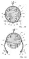
- the portion of the outer screen case 2 other than the end rings 5 and 6 is divided circumferentially into an upper section and a lower section and the lower section is further divided circumferentially into two sections whereby an upper screen section 2a and lower screen sections 2b, 2b are formed.
- the lower screen sections 2b, 2b are hingedly connected to the upper screen section 2a by means of a pair of hinges 12, 12 extending in the axial direction. Plates 13 extending in the axial direction are fixedly secured to the bottom portions (opposite end portions) of the lower screen sections 2b, 2b.
- Pistons 15, 15 extending normally to the longitudinal direction of the plates 13, 13 and fitted in hydraulic cylinders 14, 14 are fixedly secured at their base portions to the plates 13, 13.
- the lower screen sections 2b, 2b can be opened as shown in Fig. 3B and closed as shown in Fig. 3A.
- the wedge wires 7 of the upper screen section 2a are welded at their end portions to the inside surfaces of the end rings 5 and 6.
- the inner screen cases 4 are disposed in the outer screen case 2 at a predetermined interval d to define a chamber 40 for filling sludge therein.
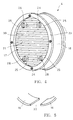
- Each of the inner screen cases 4 is constructed, as best shown in Fig. 4, by providing continuous slit screen plates 17, 17 on both ends of a short cylindrical side plate 16. These continuous slit screen plates 17, 17 extend in a direction crossing the direction of pressing by the press means 3.
- a space 18 (Fig. 6) is defined between the screen plates 17, 17 for receiving water extracted from sludge.
- Each of the screen plates 17, 17 includes support rods 20 which are arranged to extend in the vertical direction at a certain interval and wedge wires 21 which extend in a horizontal direction with their flat surfaces facing outside and are welded to the support rods 20 at crossing points therebetween.
- a slit 39 of a predetermined width is defined between respective adjacent wedge wires 21.
- the inner screen case 4 has such a diameter that, when the inner screen case 4 is disposed concentrically in the outer screen case 2, there is a slight gap between the inner peripheral surface of the outer screen case 2 and the outer peripheral surface of the inner screen case 4.
- An opening 22 shown in Fig. 5 is formed in the bottom portion of the annular side plate 16 of the inner screen case 4 to exclude water collected in the space 18.
- a pair of slide rings 23, 23 made of an elastic material such as urethane rubber are fixedly secured to the screen plates 17, 17 by means of bolts 24.
- the slide rings 23 have an outer diameter which is equal to or slightly larger than the inner diameter of the outer screen case 2 and, by pushing the slide rings 23 into the outer screen case 2, the inner screen case 4 can slide in the axial direction in the outer screen case 2 with a sealed state being formed between the inner peripheral surface of the outer screen case 2 and the outer peripheral surface of the inner screen case 4.
- each of the screen plates 17 of the inner screen case 4 is disposed securing plates 25 which are welded at one end portion thereof to the side plate 16.
- a pin 27 which constitutes a positioning means 26 of the inner screen case 4
- a circular opening 25a and a cylinder 28 which constitutes the rest of the positioning means 26 is axially slidably fitted in the opening 25a.
- the pin 27 has a head 27a of an enlarged diameter and the cylinder 28 has a circular opening 28b in an end portion 28a on the side of the pin 27.
- This opening 28b has a diameter which is slightly larger than the diameter of the pin 27 and is smaller than the diameter of the enlarged head 27a of the pin 27.
- the pin 27 is slidably fitted in the opening 28b.
- the cylinder 28 has an enlarged head portion 28c of a diameter which is larger than the diameter of the opening 25a of the securing plate 25.
- On one of the screen plates 17 of each inner screen case 4 is secured the pin 27 and on the other screen plate 17 is secured the screen 28.
- Fig. 4 shows a state of the screen plate 17 on which the cylinders 28 are secured to the securing plates 25.
- the pressing means 3 used for pressing sludge includes a pressing disk 29 which is fitted in the outer screen case 2, a piston rod 30 connected to the pressing disk 29, a drive mechanism (not shown) for reciprocating this piston rod 30 and a screen case 31 secured fixedly to the inside of the pressing disk 29.
- the screen case 31 is of a construction similar to the inner screen case 4 excepting that a screen plate is not provided on the side of the pressing disk 29 and is connected to the screen plate 17 of the adjacent inner screen case 4 by means of the positioning means 26.
- the press means 3 is provided on both ends of the outer screen case 2.
- Fig. 1 shows a state before filling sludge in the press 1.
- the interval between the respective inner screen cases 4, that is, the width d of the sludge filling chamber 40 is at the maximum.
- the positioning means 26 is in the state shown in Fig. 7.
- the pin 27 is pulled to the maximum extent away from the cylinder 28 and the enlarged head 27a of the pin 27 is engaged with the inner surface of the end portion 28a of the cylinder 28.
- the enlarged head portion 28a of the cylinder 28 is engaged With the inner surface of the securing plate 25.
- the inner screen cases 4 are located at locations in the outer screen case 2 where the sludge in lets 10 can communicate with the sludge filling chambers 40.
- the pump P is driven to fill sludge to be treated to the sludge filling chambers 40 in the outer screen case 2 through the supply pipe 11 and sludge inlets 10.
- the piston 30 of the press means 3 is driven in the direction of arrow P to press the sludge in the sludge filling chambers 40.
- the pin 27 of the positioning means 26 relatively slides in the direction of arrow B in Fig. 7 in the cylinder 28 while the cylinder 28 slides in the direction of arrow C due to reaction of the sludge received at the end portion 28a of the cylinder 28.
- the interval between the screen plates 17, 17 of the adjacent inner screen cases 4, i.e., the width d of the sludge filling chamber 40 is reduced.
- pressing is stopped.
- the hydraulic cylinders 14, 14 (Fig. 3) are operated to open the lower screen sections 2b, 2b of the outer screen case 2 as shown in Fig. 3B to allow the cake of the compressed sludge to fall to a cake receiving plate (not shown) placed below the press 1.
- the hydraulic cylinders 14, 14 are operated to close the lower screen sections 2b, 2b of the outer screen case 2 and thereby to restore the press 1 to the state shown in Fig. 3A.
- the piston 30 of the pressing means 3 is moved in the direction of arrow Q in Fig. 1 to restore the inner screen cases 4 to the position shown in Fig. 1 for a next sludge dehydrating operation.
- the positioning means for positioning the inner screen cases 4 is not limited to the one which is a combination of the pin 27 and the cylinder 28 as used in the above described embodiment but various other structures may be used.
- Fig. 8 schematically shows another example of the positioning means.
- Positioning rods 32 are fixedly secured to the respective inner screen cases 4 individually.
- the positioning rods 32 secured to the inner screen case 4 which is located remotely as viewed from the operation end of the positioning rods 32 pass through the inner screen case 4 which is located nearer to the operation end of the positioning rods 32.
- the inner screen cases 4 are restored to the start position after the sludge pressing operation by pushing the inner screen cases 4 by means of the positioning rods 32.
- Fig. 9 shows another embodiment of the invention.
- the same or similar component parts to those shown in Fig. 1 are designated by the same reference characters and description thereof will be omitted.
- This embodiment is different from the embodiment shown in Fig. 1 in that an extracted water removing screen tube 33 is provided in the central portion of the outer screen case 2.
- This screen tube 33 is fixedly secured to a frame (not shown) of the press 1 and extends through the inner screen cases 4 and the pressing disks 29 and screen cases 31 of the press means 3 through openings formed therein so that the inner screen cases 4, pressing disks 29 and screen cases 31 can slide axially with respect to the screen tube 33.
- a portion of the screen tube 33 corresponding to the outer screen case 2 is made of a wedge wire screen tube 34 consisting of axially extending support rods and a spiral wedge wire wound about the outer surfaces of the support rods, so that a part of water extracted by compression of the sludge flows into this wedge wire screen tube 34 and is removed outside through an outlet (not shown) of the screen tube 34.
- This construction enhances the sludge dehydrating effect of the press 1 and is particularly effective in a case where the press 1 has the sludge filling chambers 40 of a large capacity.
- Fig. 10 shows a still another embodiment of the invention.
- a suction inlet 42a of a known vacuum generation means 42 such as a vacuum pump is connected to an outlet 33a of the extracted water removing screen tube 33.
- a vacuum generation means 42 By driving this vacuum generation means 42, vacuum is generated to suck out the extracted water and thereby to enhance the sludge dehydrating effect further.
Landscapes
- Engineering & Computer Science (AREA)
- Mechanical Engineering (AREA)
- Health & Medical Sciences (AREA)
- Life Sciences & Earth Sciences (AREA)
- Molecular Biology (AREA)
- General Engineering & Computer Science (AREA)
- Treatment Of Sludge (AREA)
- Filtration Of Liquid (AREA)
Applications Claiming Priority (2)
| Application Number | Priority Date | Filing Date | Title |
|---|---|---|---|
| JP1401394A JP3359409B2 (ja) | 1994-01-12 | 1994-01-12 | 汚泥処理用加圧式脱水装置および汚泥処理方法 |
| JP14013/94 | 1994-01-12 |
Publications (2)
| Publication Number | Publication Date |
|---|---|
| EP0663227A1 true EP0663227A1 (de) | 1995-07-19 |
| EP0663227B1 EP0663227B1 (de) | 1998-04-22 |
Family
ID=11849318
Family Applications (1)
| Application Number | Title | Priority Date | Filing Date |
|---|---|---|---|
| EP19950100150 Expired - Lifetime EP0663227B1 (de) | 1994-01-12 | 1995-01-06 | Entwässerungspresse für Schlämme und Verfahren zur Schlammbehandlung |
Country Status (8)
| Country | Link |
|---|---|
| US (2) | US5643458A (de) |
| EP (1) | EP0663227B1 (de) |
| JP (1) | JP3359409B2 (de) |
| KR (1) | KR0127786B1 (de) |
| CN (1) | CN1079782C (de) |
| AU (1) | AU676624B2 (de) |
| CA (1) | CA2139532C (de) |
| DE (1) | DE69502113T2 (de) |
Cited By (4)
| Publication number | Priority date | Publication date | Assignee | Title |
|---|---|---|---|---|
| WO1999049269A1 (en) * | 1998-03-25 | 1999-09-30 | Antonio La Gioia | A cage compactor dryer apparatus for treating waste materials |
| RU2212927C2 (ru) * | 2001-09-28 | 2003-09-27 | Тарасов Юрий Дмитриевич | Устройство для сгущения сапропеля |
| CN104019636A (zh) * | 2014-06-03 | 2014-09-03 | 李明华 | 一种马铃薯渣脱水方法 |
| CN112373094A (zh) * | 2020-10-20 | 2021-02-19 | 廊坊市泽田依诺机械设备有限公司 | 一种固液分离压缩套 |
Families Citing this family (32)
| Publication number | Priority date | Publication date | Assignee | Title |
|---|---|---|---|---|
| JP3359409B2 (ja) * | 1994-01-12 | 2002-12-24 | 株式会社ナガオカ | 汚泥処理用加圧式脱水装置および汚泥処理方法 |
| US5954956A (en) * | 1997-07-22 | 1999-09-21 | J&L Fiber Services | Modular screen cylinder and a method for its manufacture |
| US6138838A (en) * | 1998-05-29 | 2000-10-31 | J&L Fiber Services, Inc. | Screen media and a screening passage therefore |
| KR20010054617A (ko) * | 1999-12-07 | 2001-07-02 | 김지석 | 삼각바 스크린에 의한 탈수장치 |
| AT410601B (de) * | 2000-12-29 | 2003-06-25 | Hoffmann La Roche | Sensor zur lumineszenz-optischen bestimmung eines analyten sowie reagens, das nach dem fret-prinzip arbeitet |
| JP2002210500A (ja) * | 2001-01-16 | 2002-07-30 | Togami Electric Mfg Co Ltd | 固液混合物凝集脱水装置及び固液混合物の凝集脱水方法 |
| US7448501B2 (en) * | 2005-03-14 | 2008-11-11 | Total Separation Solutions, Llc | Concentric C-shaped filter and screen topology |
| US20080073298A1 (en) * | 2005-03-14 | 2008-03-27 | Total Separation Solutions Llc | Filter having opposing parallel planes of wedge wires |
| US7438191B2 (en) * | 2006-12-15 | 2008-10-21 | Uop Llc | Angle rod screen design |
| CN101164928B (zh) * | 2007-09-25 | 2011-04-06 | 胡杭虎 | 污泥强力脱水机 |
| EP2724781B1 (de) * | 2008-09-25 | 2020-03-25 | ATOP S.p.A. | Verfahren und vorrichtung zum verdichten von behälter |
| WO2011118283A1 (ja) * | 2010-03-26 | 2011-09-29 | メタウォーター株式会社 | 固液分離方法 |
| US9266079B2 (en) * | 2012-06-20 | 2016-02-23 | Uop Llc | Apparatus for retaining solid material in a radial flow reactor and method of making |
| US8388836B1 (en) * | 2012-09-05 | 2013-03-05 | Emerald Waste Solutions, LLC | Waste separator apparatus and system for treating animal waste and the like |
| US10093570B2 (en) * | 2013-04-22 | 2018-10-09 | Paul VETTE | Dynamic dewatering system |
| EP2941963A1 (de) * | 2014-05-08 | 2015-11-11 | Royal Duyvis Wiener B.V. | Presse zum Bearbeiten einer fetthaltigen Masse |
| CN104860506B (zh) * | 2015-06-03 | 2017-07-28 | 河海大学 | 一种污泥/淤泥脱水设备及脱水方法 |
| US11118584B2 (en) | 2016-06-29 | 2021-09-14 | Itt Manufacturing Enterprises Llc | Ring section pump having intermediate tie rod combination |
| CN106839692A (zh) * | 2017-04-07 | 2017-06-13 | 中化重庆涪陵化工有限公司 | 高效干燥的卧式转筒干燥机 |
| CN107555759B (zh) * | 2017-04-08 | 2019-10-01 | 浙江威治环保科技有限公司 | 微波调理脱水干化污泥处理系统 |
| CN106861258B (zh) * | 2017-04-12 | 2018-02-27 | 江苏火焰山干燥技术有限公司 | 卧式压滤机 |
| CN108083608A (zh) * | 2017-12-20 | 2018-05-29 | 郑州艾莫弗信息技术有限公司 | 一种曲柄滑块式的污泥脱水装置 |
| CN108409102B (zh) * | 2018-05-20 | 2024-06-07 | 湖南滇湘市政建设工程有限公司 | 对开型多腔室压滤污泥脱水装置 |
| CN108529848B (zh) * | 2018-05-20 | 2020-12-01 | 广州市芦苇环保科技有限责任公司 | 对开型压滤污泥脱水方法 |
| CN108585425B (zh) * | 2018-05-20 | 2020-12-25 | 深圳深南电环保有限公司 | 对开型压滤污泥脱水装置 |
| CN108404474B (zh) * | 2018-05-20 | 2020-11-17 | 中国计量大学 | 对开型多腔室压滤污泥脱水方法 |
| CN111893985B (zh) * | 2020-07-03 | 2025-06-24 | 温州大学 | 一种组合式集装箱的真空预压装置及其真空预压方法 |
| CN112033129A (zh) * | 2020-08-28 | 2020-12-04 | 杭州伊尹健康技术有限公司 | 中药切片烘干系统 |
| CN112033096A (zh) * | 2020-08-28 | 2020-12-04 | 杭州伊尹健康技术有限公司 | 中药切片烘干方法 |
| CN112535894B (zh) * | 2020-11-06 | 2022-09-16 | 温州宾创环保科技有限公司 | 自带残渣收集功能的工业污水机构 |
| DE102022113909A1 (de) | 2022-06-02 | 2023-12-07 | Josef Trendelkamp | Filtrationselement und Filtriervorrichtung |
| CN116753681B (zh) * | 2023-08-11 | 2023-11-07 | 潍坊市经济学校 | 一种餐厨垃圾干化处理装置 |
Citations (3)
| Publication number | Priority date | Publication date | Assignee | Title |
|---|---|---|---|---|
| CH314906A (de) * | 1952-06-16 | 1956-07-15 | Hoffmann Johann | Vorrichtung zum Filtrieren von organischen Feststoff-Flüssigkeitsgemischen |
| EP0480176A1 (de) * | 1990-10-10 | 1992-04-15 | Müller Umwelttechnik GmbH & Co. KG | Verfahren zur Druckentwässerung von wässrigen Schlämmen |
| EP0587080A1 (de) * | 1992-09-11 | 1994-03-16 | Nagaoka International Corporation | Entwässerungspresse für Schlämme und Verfahren zur Behandlung von Schlämmen |
Family Cites Families (9)
| Publication number | Priority date | Publication date | Assignee | Title |
|---|---|---|---|---|
| US1566496A (en) * | 1925-12-22 | Particularly peat | ||
| US838841A (en) * | 1905-12-26 | 1906-12-18 | Gabriel Carlson | Chocolate-press. |
| US1686095A (en) * | 1924-11-20 | 1928-10-02 | Fred W Manning | Continuous expelling and clarifying process |
| US2770426A (en) * | 1952-05-28 | 1956-11-13 | Unit Mfg Company | Filter cartridge |
| US4276265A (en) * | 1979-12-26 | 1981-06-30 | Uop Inc. | Screen for collection and distribution of process streams |
| AU541539B1 (en) * | 1983-11-04 | 1985-01-10 | Dravo Corporation | Filter press |
| WO1986006326A1 (en) * | 1985-04-29 | 1986-11-06 | Idee E Prodotti S.A.S Di Di Leo Vincenzo & C. | Filtering case for separating a liquid from a solid, in particular for dehydrating slurries from industrial processes |
| JP3359409B2 (ja) * | 1994-01-12 | 2002-12-24 | 株式会社ナガオカ | 汚泥処理用加圧式脱水装置および汚泥処理方法 |
| JP5518598B2 (ja) | 2010-07-02 | 2014-06-11 | 東京エレクトロン株式会社 | パーティクル分布解析支援方法及びその方法を実施するためのプログラムを記録した記録媒体 |
-
1994
- 1994-01-12 JP JP1401394A patent/JP3359409B2/ja not_active Expired - Lifetime
- 1994-12-29 US US08/365,851 patent/US5643458A/en not_active Expired - Fee Related
-
1995
- 1995-01-04 AU AU10025/95A patent/AU676624B2/en not_active Ceased
- 1995-01-04 CA CA 2139532 patent/CA2139532C/en not_active Expired - Fee Related
- 1995-01-06 DE DE69502113T patent/DE69502113T2/de not_active Expired - Fee Related
- 1995-01-06 EP EP19950100150 patent/EP0663227B1/de not_active Expired - Lifetime
- 1995-01-10 KR KR1019950000302A patent/KR0127786B1/ko not_active Expired - Fee Related
- 1995-01-11 CN CN95101760A patent/CN1079782C/zh not_active Expired - Fee Related
-
1996
- 1996-12-02 US US08/753,896 patent/US5858235A/en not_active Expired - Fee Related
Patent Citations (3)
| Publication number | Priority date | Publication date | Assignee | Title |
|---|---|---|---|---|
| CH314906A (de) * | 1952-06-16 | 1956-07-15 | Hoffmann Johann | Vorrichtung zum Filtrieren von organischen Feststoff-Flüssigkeitsgemischen |
| EP0480176A1 (de) * | 1990-10-10 | 1992-04-15 | Müller Umwelttechnik GmbH & Co. KG | Verfahren zur Druckentwässerung von wässrigen Schlämmen |
| EP0587080A1 (de) * | 1992-09-11 | 1994-03-16 | Nagaoka International Corporation | Entwässerungspresse für Schlämme und Verfahren zur Behandlung von Schlämmen |
Cited By (5)
| Publication number | Priority date | Publication date | Assignee | Title |
|---|---|---|---|---|
| WO1999049269A1 (en) * | 1998-03-25 | 1999-09-30 | Antonio La Gioia | A cage compactor dryer apparatus for treating waste materials |
| US6298576B1 (en) | 1998-03-25 | 2001-10-09 | Antonio La Gioia | Cage compactor dryer apparatus for treating waste materials |
| RU2212927C2 (ru) * | 2001-09-28 | 2003-09-27 | Тарасов Юрий Дмитриевич | Устройство для сгущения сапропеля |
| CN104019636A (zh) * | 2014-06-03 | 2014-09-03 | 李明华 | 一种马铃薯渣脱水方法 |
| CN112373094A (zh) * | 2020-10-20 | 2021-02-19 | 廊坊市泽田依诺机械设备有限公司 | 一种固液分离压缩套 |
Also Published As
| Publication number | Publication date |
|---|---|
| CN1112523A (zh) | 1995-11-29 |
| US5643458A (en) | 1997-07-01 |
| CN1079782C (zh) | 2002-02-27 |
| KR0127786B1 (ko) | 1997-12-29 |
| EP0663227B1 (de) | 1998-04-22 |
| US5858235A (en) | 1999-01-12 |
| DE69502113T2 (de) | 1998-12-03 |
| CA2139532A1 (en) | 1995-07-13 |
| JP3359409B2 (ja) | 2002-12-24 |
| AU676624B2 (en) | 1997-03-13 |
| CA2139532C (en) | 2000-02-15 |
| AU1002595A (en) | 1995-07-20 |
| DE69502113D1 (de) | 1998-05-28 |
| KR950023609A (ko) | 1995-08-18 |
| JPH07204894A (ja) | 1995-08-08 |
Similar Documents
| Publication | Publication Date | Title |
|---|---|---|
| EP0663227B1 (de) | Entwässerungspresse für Schlämme und Verfahren zur Schlammbehandlung | |
| US5377423A (en) | Sludge dehydrating press and method for treating sludge | |
| CA1188626A (en) | Filtration thickening method and apparatus | |
| US3796316A (en) | Water filtering apparatus | |
| EP0481390A1 (de) | Rückspülverfahren und Anlage | |
| EP0001183B1 (de) | Filter | |
| BG62356B1 (bg) | Инсталация за непрекъснато пречистване на течности иобезводняване и сушене на отделените нефилтриращи се твърдичастици | |
| US4836937A (en) | System for removing liquid from a slurry of liquid and powdered material | |
| US4042506A (en) | Apparatus for removing solid material from sewage or other liquid | |
| EP0311716B1 (de) | Filtrieranordnung und Verfahren | |
| CN110302586A (zh) | 一种中药浸取液过滤装置 | |
| CN113350875A (zh) | 一种污泥脱水残余物净化过滤设备 | |
| US3997446A (en) | Filter apparatus with an accordion-type filter medium for compaction and removal of sludgy filter cake | |
| JPH05318189A (ja) | 汚泥処理用加圧式脱水装置および汚泥処理方法 | |
| DE2731043A1 (de) | Doppelt wirkende filterpresse | |
| US5034128A (en) | Apparatus for dewatering pulp | |
| GB2086751A (en) | Platen press | |
| KR102461500B1 (ko) | 초고압을 이용한 압착식 탈수장치 | |
| CN117778165B (zh) | 一种用于青稞麦绿素提取的超声波破壁提取装置 | |
| JPH08252411A (ja) | スクリーン装置 | |
| SU1611390A1 (ru) | Устройство дл обезвоживани суспензий | |
| JPH10296013A (ja) | 脱水装置および該装置に使用する圧送機並びに脱水機 | |
| SU829135A1 (ru) | Фильтр дл очистки сточных вод | |
| CA2101732A1 (en) | Method and device for separating liquid/solid mixtures | |
| JP2001191061A (ja) | クラゲ高速脱水処理装置 |
Legal Events
| Date | Code | Title | Description |
|---|---|---|---|
| PUAI | Public reference made under article 153(3) epc to a published international application that has entered the european phase |
Free format text: ORIGINAL CODE: 0009012 |
|
| AK | Designated contracting states |
Kind code of ref document: A1 Designated state(s): BE CH DE FR GB IT LI NL |
|
| 17P | Request for examination filed |
Effective date: 19950816 |
|
| 17Q | First examination report despatched |
Effective date: 19961206 |
|
| GRAG | Despatch of communication of intention to grant |
Free format text: ORIGINAL CODE: EPIDOS AGRA |
|
| GRAG | Despatch of communication of intention to grant |
Free format text: ORIGINAL CODE: EPIDOS AGRA |
|
| GRAH | Despatch of communication of intention to grant a patent |
Free format text: ORIGINAL CODE: EPIDOS IGRA |
|
| GRAH | Despatch of communication of intention to grant a patent |
Free format text: ORIGINAL CODE: EPIDOS IGRA |
|
| GRAA | (expected) grant |
Free format text: ORIGINAL CODE: 0009210 |
|
| AK | Designated contracting states |
Kind code of ref document: B1 Designated state(s): BE CH DE FR GB IT LI NL |
|
| PG25 | Lapsed in a contracting state [announced via postgrant information from national office to epo] |
Ref country code: NL Free format text: LAPSE BECAUSE OF FAILURE TO SUBMIT A TRANSLATION OF THE DESCRIPTION OR TO PAY THE FEE WITHIN THE PRESCRIBED TIME-LIMIT Effective date: 19980422 Ref country code: LI Free format text: LAPSE BECAUSE OF FAILURE TO SUBMIT A TRANSLATION OF THE DESCRIPTION OR TO PAY THE FEE WITHIN THE PRESCRIBED TIME-LIMIT Effective date: 19980422 Ref country code: IT Free format text: LAPSE BECAUSE OF FAILURE TO SUBMIT A TRANSLATION OF THE DESCRIPTION OR TO PAY THE FEE WITHIN THE PRESCRIBED TIME-LIMIT;WARNING: LAPSES OF ITALIAN PATENTS WITH EFFECTIVE DATE BEFORE 2007 MAY HAVE OCCURRED AT ANY TIME BEFORE 2007. THE CORRECT EFFECTIVE DATE MAY BE DIFFERENT FROM THE ONE RECORDED. Effective date: 19980422 Ref country code: CH Free format text: LAPSE BECAUSE OF FAILURE TO SUBMIT A TRANSLATION OF THE DESCRIPTION OR TO PAY THE FEE WITHIN THE PRESCRIBED TIME-LIMIT Effective date: 19980422 |
|
| REG | Reference to a national code |
Ref country code: CH Ref legal event code: EP |
|
| REF | Corresponds to: |
Ref document number: 69502113 Country of ref document: DE Date of ref document: 19980528 |
|
| ET | Fr: translation filed | ||
| NLV1 | Nl: lapsed or annulled due to failure to fulfill the requirements of art. 29p and 29m of the patents act | ||
| REG | Reference to a national code |
Ref country code: CH Ref legal event code: PL |
|
| PG25 | Lapsed in a contracting state [announced via postgrant information from national office to epo] |
Ref country code: BE Free format text: LAPSE BECAUSE OF NON-PAYMENT OF DUE FEES Effective date: 19990131 |
|
| PLBE | No opposition filed within time limit |
Free format text: ORIGINAL CODE: 0009261 |
|
| STAA | Information on the status of an ep patent application or granted ep patent |
Free format text: STATUS: NO OPPOSITION FILED WITHIN TIME LIMIT |
|
| 26N | No opposition filed | ||
| BERE | Be: lapsed |
Owner name: NAGAOKA INTERNATIONAL CORP. Effective date: 19990131 |
|
| REG | Reference to a national code |
Ref country code: GB Ref legal event code: IF02 |
|
| PGFP | Annual fee paid to national office [announced via postgrant information from national office to epo] |
Ref country code: GB Payment date: 20021216 Year of fee payment: 9 |
|
| PGFP | Annual fee paid to national office [announced via postgrant information from national office to epo] |
Ref country code: FR Payment date: 20030120 Year of fee payment: 9 |
|
| PGFP | Annual fee paid to national office [announced via postgrant information from national office to epo] |
Ref country code: DE Payment date: 20031230 Year of fee payment: 10 |
|
| PG25 | Lapsed in a contracting state [announced via postgrant information from national office to epo] |
Ref country code: GB Free format text: LAPSE BECAUSE OF NON-PAYMENT OF DUE FEES Effective date: 20040106 |
|
| GBPC | Gb: european patent ceased through non-payment of renewal fee |
Effective date: 20040106 |
|
| PG25 | Lapsed in a contracting state [announced via postgrant information from national office to epo] |
Ref country code: FR Free format text: LAPSE BECAUSE OF NON-PAYMENT OF DUE FEES Effective date: 20040930 |
|
| REG | Reference to a national code |
Ref country code: FR Ref legal event code: ST |
|
| PG25 | Lapsed in a contracting state [announced via postgrant information from national office to epo] |
Ref country code: DE Free format text: LAPSE BECAUSE OF NON-PAYMENT OF DUE FEES Effective date: 20050802 |