EP0663263B1 - Anlage zum Vermeiden von thermischen Verformungen einer Werkzeugmaschine - Google Patents
Anlage zum Vermeiden von thermischen Verformungen einer Werkzeugmaschine Download PDFInfo
- Publication number
- EP0663263B1 EP0663263B1 EP19940100518 EP94100518A EP0663263B1 EP 0663263 B1 EP0663263 B1 EP 0663263B1 EP 19940100518 EP19940100518 EP 19940100518 EP 94100518 A EP94100518 A EP 94100518A EP 0663263 B1 EP0663263 B1 EP 0663263B1
- Authority
- EP
- European Patent Office
- Prior art keywords
- heat exchanging
- machine tool
- heat
- transfer fluid
- heat transfer
- Prior art date
- Legal status (The legal status is an assumption and is not a legal conclusion. Google has not performed a legal analysis and makes no representation as to the accuracy of the status listed.)
- Expired - Lifetime
Links
- 239000013529 heat transfer fluid Substances 0.000 claims description 38
- 238000007599 discharging Methods 0.000 claims description 36
- 238000001816 cooling Methods 0.000 claims description 23
- 238000010438 heat treatment Methods 0.000 claims description 16
- 239000000463 material Substances 0.000 claims description 5
- 238000005086 pumping Methods 0.000 claims 4
- 239000003921 oil Substances 0.000 description 61
- XLYOFNOQVPJJNP-UHFFFAOYSA-N water Substances O XLYOFNOQVPJJNP-UHFFFAOYSA-N 0.000 description 27
- 239000002826 coolant Substances 0.000 description 14
- 239000011800 void material Substances 0.000 description 11
- 230000008859 change Effects 0.000 description 9
- 238000003754 machining Methods 0.000 description 4
- 239000012530 fluid Substances 0.000 description 3
- 230000007246 mechanism Effects 0.000 description 3
- 238000003801 milling Methods 0.000 description 3
- 239000010730 cutting oil Substances 0.000 description 2
- 238000010586 diagram Methods 0.000 description 2
- JEIPFZHSYJVQDO-UHFFFAOYSA-N iron(III) oxide Inorganic materials O=[Fe]O[Fe]=O JEIPFZHSYJVQDO-UHFFFAOYSA-N 0.000 description 2
- 238000011084 recovery Methods 0.000 description 2
- 238000003756 stirring Methods 0.000 description 2
- 238000012546 transfer Methods 0.000 description 2
- 229910001018 Cast iron Inorganic materials 0.000 description 1
- YCKRFDGAMUMZLT-UHFFFAOYSA-N Fluorine atom Chemical compound [F] YCKRFDGAMUMZLT-UHFFFAOYSA-N 0.000 description 1
- 229910000831 Steel Inorganic materials 0.000 description 1
- 230000002411 adverse Effects 0.000 description 1
- 238000007796 conventional method Methods 0.000 description 1
- 238000013461 design Methods 0.000 description 1
- 230000000694 effects Effects 0.000 description 1
- 230000003028 elevating effect Effects 0.000 description 1
- 238000002474 experimental method Methods 0.000 description 1
- 239000011737 fluorine Substances 0.000 description 1
- 229910052731 fluorine Inorganic materials 0.000 description 1
- 230000020169 heat generation Effects 0.000 description 1
- 239000008236 heating water Substances 0.000 description 1
- 238000003780 insertion Methods 0.000 description 1
- 230000037431 insertion Effects 0.000 description 1
- 238000000034 method Methods 0.000 description 1
- 238000012986 modification Methods 0.000 description 1
- 230000004048 modification Effects 0.000 description 1
- 238000012544 monitoring process Methods 0.000 description 1
- 239000011347 resin Substances 0.000 description 1
- 229920005989 resin Polymers 0.000 description 1
- 239000010959 steel Substances 0.000 description 1
Images

Classifications
-
- B—PERFORMING OPERATIONS; TRANSPORTING
- B23—MACHINE TOOLS; METAL-WORKING NOT OTHERWISE PROVIDED FOR
- B23Q—DETAILS, COMPONENTS, OR ACCESSORIES FOR MACHINE TOOLS, e.g. ARRANGEMENTS FOR COPYING OR CONTROLLING; MACHINE TOOLS IN GENERAL CHARACTERISED BY THE CONSTRUCTION OF PARTICULAR DETAILS OR COMPONENTS; COMBINATIONS OR ASSOCIATIONS OF METAL-WORKING MACHINES, NOT DIRECTED TO A PARTICULAR RESULT
- B23Q11/00—Accessories fitted to machine tools for keeping tools or parts of the machine in good working condition or for cooling work; Safety devices specially combined with or arranged in, or specially adapted for use in connection with, machine tools
- B23Q11/14—Methods or arrangements for maintaining a constant temperature in parts of machine tools
- B23Q11/143—Methods or arrangements for maintaining a constant temperature in parts of machine tools comprising heating means
-
- B—PERFORMING OPERATIONS; TRANSPORTING
- B23—MACHINE TOOLS; METAL-WORKING NOT OTHERWISE PROVIDED FOR
- B23Q—DETAILS, COMPONENTS, OR ACCESSORIES FOR MACHINE TOOLS, e.g. ARRANGEMENTS FOR COPYING OR CONTROLLING; MACHINE TOOLS IN GENERAL CHARACTERISED BY THE CONSTRUCTION OF PARTICULAR DETAILS OR COMPONENTS; COMBINATIONS OR ASSOCIATIONS OF METAL-WORKING MACHINES, NOT DIRECTED TO A PARTICULAR RESULT
- B23Q11/00—Accessories fitted to machine tools for keeping tools or parts of the machine in good working condition or for cooling work; Safety devices specially combined with or arranged in, or specially adapted for use in connection with, machine tools
- B23Q11/14—Methods or arrangements for maintaining a constant temperature in parts of machine tools
- B23Q11/141—Methods or arrangements for maintaining a constant temperature in parts of machine tools using a closed fluid circuit for cooling or heating
Definitions
- the present invention relates to an apparatus for preventing thermal deformation of a machine tool, according to the pre-characterizing part of claim 1 or claim 2 ; it also relates to a machine tool having such apparatus.
- a conventional machine tool is provided with oil jackets placed around the bearing mechanism of a spindle and the like.
- a coolant such as a cutting oil is circulated through the oil jackets to prevent the machine tool from excessive heating, whereby the machine tool is adjusted of its thermal balance and is suppressed of its thermal deformation.
- EP-A-355730 discloses an apparatus of the type defined in the pre-characterizing part of both claims 1 and 2.
- the heat exchanging means are in the form of tube like channels similar to the above-mentioned oil jackets.
- the provision of the oil jackets causes the machine tool complicated in structure. Further, there is a fear that the inner portions of the oil jackets will rust due to the coolant flowing therethrough. Furthermore, the portions of the machine tool which are cooled by the coolant are limited to the places where the oil jackets are provided, so that in the case that the thermal balance is changed owing to the atmosphere in which the machine tool is placed, the portions to be cooled cannot easily be modified in order to effectively suppress the thermal deformation occurred in the machine tool.
- the object of the present invention is to provide an apparatus for preventing thermal deformation occurred in a machine tool, which is capable of suppressing the thermal deformation of the machine tool without causing the machine tool to be complicated in structure.
- One or more heat exchanging portions can easily be attached on desired portions of the machine tool.
- the apparatus for preventing thermal deformation occurred in a machine tool is capable of heating and/or cooling desired portions of the machine tool.
- the present invention provides an apparatus for preventing thermal deformation of a machine tool which is capable of performing suitable heating and/or cooling operations of the desired portions of the machine tool in accordance with an amount of heat transfer to the respective portions of the machine tool by a heat transfer fluid.
- Further subject-matter of the invention is a machine tool equipped with the disclosed apparatus for preventing heat deformation of the machine tool.
- the heat exchanging means has at least one heat exchanging unit which is bag-shaped and made of flexible material so that it is capable of being expanded and shrunk in accordance with the heat transfer fluid therein. It is perferable that the heat exchanging means is releasably connected between the feed means and the discharging means by means of joint means. Usually, the heat exchanging means has a plurality of the heat exchanging units. These heat exchanging units can be connected in serial or in parallel. It is also preferable that the discharging means is connected to the feed means so that the heat transfer fluid passed through the heat exchanging means is fed back to the feed means.
- a control means which detects a temperature of the heat transfer fluid when flowing into and discharging from the heat exchanging means and controls the heating means to heat the heat transfer fluid based on detected temperature of the heat transfer fluid.
- a cooling means for cooling the heat transfer fluid may be provided, together with the heating means.
- the control means is designed so that it controls to drive the heating means and the cooling means selectively based on the detected temperature of the heat transfer fluid.
- the heat exchanging means is arranged in a portion of thermally lower side of the machine tool, and the heat transfer fluid is supplied to the heat exchanging means from the feed means.
- the portion of the machine tool where the heat exchanging means is arranged is heated by the heat transfer fluid flowing through the heat exchanging means. As a result, each portion of the machine tool becomes thermally equalized, whereby thermal deformation of the machine tool can be suppressed.
- the heat exchanging means according to the present invention is capable of being expanded and shrunk according to the amount of fluid contained therein. Therefore, the heat exchanging means is set in a shrunk condition and is arranged in the portion of the machine tool.
- the heat exchanging means arranged in the machine tool is expanded by supplying the fluid from the feed means via the flow control means. As a result, the expanded heat exchanging means is placed in the prescribed portion of the machine tool in such a manner that the outer surface thereof is fixedly contacted with the inner surface of the portion.
- the heat exchanging means can easily be placed even in a narrow portion of the machine tool.
- the portion of the machine tool where the heat exchanging means is to be placed can easily be changed according to the thermal condition of the machine tool.
- the heat transfer from the heat transfer fluid passing through the heat exchanging means to the portion of the machine tool can be carried out effectively.
- the machine tool is not directly contacted with the heat transfer fluid, it is prevented from rusting.
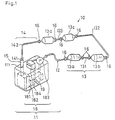
- an apparatus 10 for preventing thermal deformation of a machine tool has a feed unit 11 for feeding a cooled or heated oil, and a heat exchanging portion 13 having four heat exchanging units 13a, 13b, 13c and 13d which is supplied with the oil from the feed unit 11 via a feed pipe 12 and cools or heats respective portions of a machine tool where these heat exchanging units are arranged.
- the apparatus 10 also has an oil discharging portion 14 which is connected to the heat exchanging unit 13d positioned at the most downstream side of the heat exchanging portion 13. The oil discharging portion 14 recovers the oil passed through the heat exchanging portion 13 and feeds it back to the feed unit 11.
- a flow control valve 15 is provided between the oil discharging portion 14 and the feed unit 11, which controls the flow rate of the oil passing through the heat exchanging portion 13.
- the feed unit 11 is provided therein with an oil coolant device 18 which has an oil reservoir 181, a filter 182 and a coolant pump 183.
- the coolant pump 183 is supplied with the oil from the reservoir 181 via the filter 182, and cools it with fluorine gas, thereafter pumps out the cooled oil to the heat exchanging portion 13.
- a cooling device and a feed pump may be provided separately.
- the feed unit 11 is also provided therein with a heater 19 for heating the oil.
- the coolant pump 183 is driven so that it functions only as a feed pump and at the same time the heater is driven to heat the oil.
- a feed pump for feeding the heated oil may be provided independently.
- the coolant pump 183 and the heater 19 are controlled by a control unit 184 provided in the feed unit 11.
- the oil is fed to the heat exchanging portion 13 without cooled where the oil temperature is detected by an appropriate means such as a bimetal thermometer that it is lower than a prescribed value such as the atmospheric temperature. While, where the oil temperature is detected that it is high above a prescribed temperature, the oil is fed to the heat exchanging portion 13 without heated.
- the feed unit 11 is provided with a level meter or a float switch (not shown) for monitoring the amount of oil stored in the reservoir 181.
- the coolant pump 183 has a bypass type cleaner (not shown).
- the oil reservoir 181 of the feed unit 11 has an oil recovery port 111 which is connected via the flow control valve 15 to an oil discharging port 141 of an oil discharging pipe 142 constituting the oil discharging portion 14. With the flow control valve 15 provided, the flow rate of the oil circulating through the heat exchanging portion 13 can be adjusted.
- the heat exchanging portion 13 has four heat exchanging units 13a, 13b, 13c and 13d of the same size and structure. These heat exchanging units are bag-shaped and made of low stretchable, flexible material so that they are expandable or shrinkable in accordance with the flow rate of the oil passing therethrough.
- the respective heat exchanging units are shown in an expanded state, wherein the respective units are fusiformed generally.
- the heat exchanging units may be made in any other appropriate form so long as they are expandable and shrinkable in accordance with the flow rate of the oil passing therethrough.
- the heat exchanging units 13a to 13d are connected in serial. That is, the first heat exchanging unit 13a is connected at its outlet port via a feed pipe 131 to an inlet port of the adjacent second heat exchanging unit 13b, which, in turn, is connected at its outlet port via a feed pipe 132 to an inlet port of the third heat exchanging unit 13c. Likewise, an outlet port of the third heat exchanging unit 13c is connected via a feed pipe 133 to an inlet port of the fourth heat exchanging unit 13d. An inlet port of the first heat exchanging unit 13a is connected via the feed pile 12 to the feed unit 11, while an outlet port of the fourth heat exchanging unit 13d is connected via the discharging pipe 142 to the feed unit side.
- the pipes 131 to 133, 12, and 142 are flexible and are easily arranged in and around a machine tool.
- the flexible feed pipes 131 to 133 are releasably connected to the respective heat exchanging units 13a to 13d.
- the second heat exchanging unit 13b is provided at its inlet and outlet ports with pipe joints 16, 16.
- the pipe joint 16 has a collar and retaining projection extending inwardly from the collar. By inserting the pipe in the collar of the joint 16, the retaining projection engages with the outer circumferential surface of the pipe to form an automatic connection between the joint and the pipe.
- the pipe can be automatically removed from the joint 16 by pushing the collar of the joint inwardly so that the projection move to a non-engaging position with the pipe.
- the pipes 12 and 142 are also releasably connected to the heat exchanging units 13a and 13d, respectively.
- the joint 16 may be of any other suitable conventional structure so long as it forms releasable connection.
- FIGS 2 and 3 show a machine tool, to which the apparatus 10 of the present example can be provided.
- a machine tool 20 has a base 21 made of cast iron, on which a headstock 22 and a slide table unit 23 are mounted.
- a feed motor 24 is provided at the side of the slide table unit 23 for driving the table 23 to slide.
- a driving motor for a spindle 221 of the headstock 22 and the like are mounted.
- the electrical power supplied to the machine tool 20 is partially consumed in the form of thermal energy, so that the machine tool is heated and suffered from thermal deformation.
- the thermal deformation occurred in the machine tool adversely affects the machining accuracy thereof or the like.
- the heat deformation of the machine tool 20 can effectively be suppressed by the provision of the apparatus 10 of the present example.
- the headstock 22 having the spindle rotating at a high speed is one that generates the largest amount of heat. If the heat symmetry of the base 21 is deteriorated by the heat generated from the headstock 22, the heat deformation occurs in the machine tool 20.
- the apparatus 10 is, for example, provided to the machine tool 20 so as to heat the low temperature side of the base 21. In the following, the oil having a temperature maintained at around 40 degrees of Centigrade is circulated through the heat exchanging portion 13 to heat the low temperature side of the machine tool 20.
- the machine tool 20 is designed to accommodate four heat exchanging units 13a to 13d.
- the machine tool 20 has the base 21 provided therein with two recessed portions 211, 212 and two void portions 213, 214.
- the recessed portions 211 and 212 are formed on the inner sides of leg portions of the base 21.
- the recessed portions 211, 212 and the void portions 213, 214 can by formed by any one of conventional appropriate methods.
- the void portions 213 and 214 have openings 213a and 214a, respectively, exposing from the front surface of the base 21.
- the void portion 213 is linked via a passage 215 formed in the base 21 to the recessed portion 211.
- the other void portion 214 is linked via a passage 216 formed in the base 21 to the recessed portion 212.
- the machine too 20 has four places for receiving the heat exchanging units 13a to 13d, the number of places for receiving the heat exchanging units can be varied according to the number of portions of machine tool to be heated or cooled.
- the heat exchanging units 13a to 13d are arranged in the respective portions 211 to 214 as follows. First, the respective heat exchanging units 13a to 13d are disassembled from the feed unit 11 by removing the feed pipes 12, 131 to 133 and the discharging pipe 142. Then, the first and fourth heat exchanging units 13a and 13d are inserted into the void portions 213 and 214, respectively, through the openings 213a and 214a.
- these heat exchanging units 13a and 13d are shrank to a certain degree by discharging oil or air contained therein so as to be able to insert into the respective void portions 213 and 214.
- the heat exchanging unit 13a is connected with the feed pipe 131 beforehand and is inserted into the void portion 213 from the side of the connected feed pipe 131.
- the heat exchanging unit 13a and the feed pipe 131 are arranged in the void portion 213 and the passage 215, respectively. Insertion of the heat exchanging unit 13d and the feed pipe 133 is carried out in the same manner as that of the heat exchanging unit 13a and the feed pipe 131.
- the second and third heat exchanging units 13b and 13c are inserted into the corresponding recessed portions 211 and 212, and thereafter they are connected with each other by the feed pipe 133.
- the heat exchanging units 13b and 13c are connected to the feed pipes 131 and 133 formerly arranged in the base 21.
- the first and fourth heat exchanging units 13a and 13d are connected with the feed pipe 12 and the discharging pipe 142, respectively.
- the apparatus 10 of Figure 1 where the four heat exchanging units 13a to 13d are connected in serial is arranged in the machine tool 20.
- the heated oil is supplied from the feed unit 11 and circulated through the four heat exchanging units 13a to 13d. Since the flow rate of the oil circulating through the heat exchanging units 13a to 13d is controlled by the control valve 15 inserted between the discharging pipe 142 and the feed unit 11, the respective heat exchanging units 13a to 13d are maintained in an expanded state, so that the outer surfaces of the respective units are set fixedly contacted with the inner surfaces of the portions 211 to 214 of the machine tool 20 where these units are accommodated. Therefore, in each of the heat exchanging units 13a to 13d, heat exchanging operation is effectively carried out between the oil supplied thereto and the portion of the machine tool. Thus, even if the portion of the machine tool 20 where the headstock 22 is mounted is heated during the operation thereof, the heat symmetry of the base 21 is maintained since the low temperature side of the base 21 is heated by the heat exchanging units 13a to 13d.
- the heat deformation of the machine tool 20 can be suppressed to at least 25 % of that occurred in the machine tool without the apparatus of the present example and that the machining accuracy thereof can be maintained.
- the machine tool 20 is heated by the heat exchanging units 13a to 13d.
- the machine tool 20 may be cooled by the heat exchanging units arranged in portions of high temperature side of the machine tool so that the machine tool is prevented from heat deforming.
- the heat exchanging units 13a to 13d are supplied with oil cooled by the oil coolant pump 183.
- the machine tool 20 of the present example is heated at its low temperature side by the heat exchanging units 13a to 13d provided therein, the heat deformation thereof can be suppressed without provision of a cooling oil jacket or with a minimum provision of such a cooling oil jacket.
- the oil circulating through the heat exchanging units 13a to 13d does not directly contact with the respective portions of the machine tool 20, so that it does not cause to rust these portions of the machine tool.
- the positions of the heat exchanging units 13a to 13d arranged in the machine tool can easily be changed accordingly, whereby the heat symmetry of the machine tool can be maintained irrespective of the change in atmosphere of the machine tool.
- the feed unit 11 of the apparatus 10 has cooling and heating means for oil, so that cooling and/or heating of the machine tool can be carried out selectively.
- the heat exchanging units 13a to 13d of the apparatus 10 are in the from of bag made of stretchable material and is capable of being expanded or shrunk, they can easily be inserted into prescribed narrow portions of the machine tool in a shrunk state. Further, these heat exchanging units are maintained in an expanded state in operation, so that they are fixedly contacted with the portions of the machine tool. Therefore, the machine tool can effectively be cooled or heated by the heat exchanging units.
- the heat exchanging units 13a to 13d and the corresponding feed pipes are releasably connected with each other by means of the pipe joints 16, it is easy to connect a desired number of heat exchanging units and assemble in the machine tool. Further, according to the present example, the oil is circulated between the feed unit 11 and the heat exchanging units 13a to 13d, and therefore a limited amount of oil can be used effectively.
- the flow control valve 15 is provided to control the flow rate of the oil circulating through the heat exchanging units 13a to 13d.
- the flow rate of the oil can be adjusted, for example, by controlling the feed rate of oil from the coolant pump 183 in accordance with the discharging rate of oil from the discharging portion 14.
- the heat exchanging units can be connected in serial or in parallel.
- the connecting mode of the heat exchanging units, the number thereof and the like depend on the size or structure of the machine tool to which the heat exchanging units are assembled, and so they are not limited to those of the present example.
- the heat exchanging units are arranged in the base of the machine tool according to the present example, they may be arranged other than these portions of the machine tool.
- the positions of the heat exchanging units are assembled are determined in accordance with the thermal distribution of the machine tool, which are not limited to the present example so long as the thermal deformation of the machine tool can be suppressed effectively.
- the oil fed to the heat exchanging units is cooled by utilizing the coolant pump 183.
- a means for cooling oil is not limited to the coolant pump, but may be any other suitable means.
- the heater 19 may be replaced by any other suitable means. Further, either one of cooling means or heating means may be eliminated from the feed unit 11.
- control of cooling and heating the oil in the feed unit 11 is carried out based on the ambient temperature. Instead, this can be carried out by detecting continuously or intermittently the temperatures of the respective portions of the machine tool to be cooled or heated and controlling the temperature of oil based on the detected temperatures.
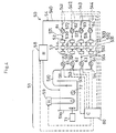
- FIG. 4 is a schematic diagram of an apparatus for preventing heat deformation of a machine tool according to the second example of the present invention.
- the apparatus 50 comprises a feed unit 51 which has a water reservoir 51a, a heater 59 for heating water stored in the reservoir 51a, a stirring machine 71 for stirring water in the reservoir 51a and a sensor 72 for detecting a temperature of water in the reservoir 51a.
- An outlet port of the reservoir 51a is connected via a feed pipe 510 and four branch pipes 511 to 514 therefrom to the suction ports of feed pumps 61 to 64.
- the respective pumps 61 to 64 are connected at their discharging ports with feed pipes 521 to 524, which in turn are releasably connected to a heat exchanging portion 53 by means of pipe joints 561 to 564.
- the heat exchanging portion 53 comprises four heat exchanging units 53a to 53d of the same structure.
- Each of the heat exchanging units 53a to 53d includes three heat exchanging bags 531 to 533.
- the respective heat exchanging units 53a to 53d are releasably connected at their exit sides with branch pipes 541 to 544 by means of pipe joints 571 to 574, respectively.
- These branch pipes 541 to 544 are connected to a discharging pipe 542 constituting the discharging portion 54.
- the branch pipes 541 to 544 are provided with sensors 81 to 84 for detecting the temperatures of water discharging from the respective heat exchanging units 53a to 53d.
- the discharging pipe 540 is connected via a radiator 58 to the reservoir 51a of the feed unit 51.
- the radiator 50 of the present example can be adjusted of its cooling capability by controlling the rotational speed of a motor fun thereof.
- each of the heat exchanging units 53a to 53d includes three heat exchanging bags 531 to 533 connected in serial having the same structure as those of the heat exchanging units 13a to 13d of the first example as described above. More specifically, each of the bags 531 to 533 is formed by a flexible sheet material made of resin, rubber or the like, and is capable of being expanded or shrunk in accordance with the amount of water passing therethrough.
- the bags 531 to 533 constituting each of the heat exchanging unit 53a to 53d are releasably connected by means of pipe joints having the same structure as those of the pipe joints 561 to 564. Instead of providing a plurality of heat exchanging bags, one or more of the heat exchanging units 53a to 53d may be comprised by a single heat exchanging bag.
- the feed unit 51 is also provided with a control unit 80 which monitors the change in temperature of water between flowing into and discharging from the heat exchanging portion 53 based on the outputs of the respective sensors 72 and 81 to 84.
- the control unit 80 controls the respective pumps 81 to 84 to adjust the feed rate of water to the heat exchanging portion 54, and also controls the heater 59 and radiator 58.
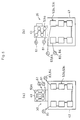
- Figures 5(a) and 5(b) illustrate the apparatus 50 of the present example being arranged in a lathe 30 and a milling machine 35, respectively.
- the first heat exchanging unit 53a is arranged in respective body portions 41 of the lathe 30 and the milling machine 35
- the second and third heat exchanging units 53b and 53c are arranged in respective bases 42 thereof.
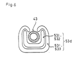
- the remaining heat exchanging unit 53d is arranged around respective spindle portions 43 as shown in Figure 6, wherein since excessive heat generation occurs in the spindle portion 43, two or more heat exchanging bags 531 to 533 constituting the heat exchanging unit 53d are wound around the spindle portion 43 in an overlapped condition so as to prevent heat generated from the spindle portion 43 from transferring to the surrounding portions thereof.
- the respective heat exchanging units 53a to 53d are supplied with water of prescribed temperature as a heat transfer fluid from the feed unit 51, whereby the spindle portion 43, the body portion 41 and the base 42 are cooled or heated by the water passing through the corresponding heat exchanging units so that the temperatures of these portions are equalized. More specifically, the surroundings of the spindle 43 is cooled by the heat exchanging unit 53d as it generates an excessive amount of heat, while the base 42 is heated by water passing through the heat exchanging units 53b and 53c as it does not generate heat. Accordingly, the respective portions of the machine tool is equalized in temperature and therefore the thermal deformation of the machine tool can be suppressed.
- the temperature of water is detected when flowing into and discharging from the respective heat exchanging units 53a to 53d by means of sensors 81 to 84. Based on the outputs of the sensors, the controller 80 calculates the heat capacity of water and controls the radiator 58 and the heater 59 so that the temperature of water circulating through the heat exchanging units is maintained to be constant. That is, where the water absorbs a certain amount of heat from the machine tool that is larger than that of heat discharged from the water to the machine tool, an amount of heat corresponding to the difference therebetween must be discharged from the water through the radiator 58.
- the amount of heat which must be discharged can be determined as the entropy change measured from the change in temperature of water between flowing into and discharging from each of the heat exchanging units and the specific heat of water. Hence, the total amount of heat which must be discharged from water through the radiator can be calculated as the sum of entropy change in each of the heat exchanging units. Based on the calculated value, the controller 80 controls to drive the radiator 58 so as to maintain the temperature of water to be constant. On the other hand, if the amount of heat discharging from the water is larger, an amount of heat corresponding to the difference therebetween is applied to the water to thereby maintain the temperature of water to be constant.
- the apparatus 50 of the present example such effects as those of the first example of the present invention can be obtained, that is, the heat deformation of the machine tool can be suppressed without providing cooling oil jacket therein, the heat exchanging units are arranged in narrow spaces in the machine tool since they can be shrunk, and the like.
- the controller 80 monitors an amount of heat discharged from or absorbed into the water based on the outputs of the sensors 81 to 84, and 72, and controls to heat or cool the water, so that the temperature of the water can be maintained to be constant.
- the machining accuracy of the machine tool which is provided with the apparatus 50 of the present example was found to be enhanced to be six times as high as that obtained without providing the apparatus 50.
- the apparatus for preventing heat deformation of a machine tool is characterized in that the heat exchanging portion for controlling the temperature of the desired portions of the machine tool is capable of being expanded or shrunk. Therefore, according to the present invention, since desired portions of the machine tool can be cooled or heated easily and effectively, the deformation of the machine tool can be suppressed without the provision of conventional cooing oil jackets or with a minimum provision thereof.
- the heat transfer fluid such as oil, water or the like does not directly contact the respective portions of the machine tool , so that the machine tool is prevented from rusting by the fluid.
- the position of the heat exchanging portion attached to the machine tool can easily be modified in order to compensate the change in the thermal distribution.
- the heat exchanging portion can be expanded or shrunk, it can easily be arranged even in a narrow space of the machine tool, and thus the limitation to places where the heat exchanging portions are provided can be minimized.
- the heat exchanging portion is arranged in a fixedly contacted state to the machine tool, so that an effective heating or cooling can be carried out.
- a plurality of heat exchanging portions are releasably connected in serial or in parallel by means of the pipe joints. Therefore, a plurality of portions of the machine tool can be cooled or heated by the apparatus of the present invention. In addition, the change of portions to be cooled or heated can easily be carried out.
- the discharging portion is connected to the feed unit to circulate the heat transfer fluid through the feed unit and the heat exchanging portion, a small amount of heat transfer fluid can be used economically.
Landscapes
- Engineering & Computer Science (AREA)
- Mechanical Engineering (AREA)
- Machine Tool Units (AREA)
- Automatic Control Of Machine Tools (AREA)
Claims (12)
- Eine Vorrichtung (10, 50) zum Verhindern einer thermischen Verformung einer Werkzeugmaschine (20; 30; 35), aufweisend: eine Zuführeinrichtung (11, 51), welche eine Erwärmungseinrichtung (19, 59) für ein Wärmeübertragungsfluid und eine Herauspumpeinrichtung (183, 61-64) zum Herauspumpen des Wärmeübertragungsfluids aufweist, das durch die Erwärmungseinrichtung (19, 59) erwärmt worden ist, eine Wärmeaustauscheinrichtung (13, 53), welche mit dem Wärmeübertragungsfluid von der Zuführeinrichtung (11, 51) über eine Leitungseinrichtung (12, 510) versorgt wird und einen Bereich der Werkzeugmaschine (20, 30, 35) erwärmt, in welchem die Wärmeaustauscheinrichtung (13, 53) anzuordnen ist, eine Abgabeeinrichtung (14, 54) zum Abgeben des Wärmeübertragungsfluids, das durch die Wärmeaustauscheinrichtung (13, 53) hindurchgegangen ist, und eine Strömungssteuereinrichtung (184, 80) zum Steuern einer Strömungsgeschwindigkeit des Wärmeübertragungsfluids, das durch die Wärmeaustauscheinrichtung (13, 53) hindurchgeht,
dadurch gekennzeichnet,
daß die Wärmeaustauscheinrichtung (13, 53) nach Maßgabe einer Menge des in ihr enthaltenen Wärmeübertragungsfluids ausdehnbar und zusammenziehbar ist. - Eine Vorrichtung (10, 50) zum Verhindern einer thermischen Verformung einer Werkzeugmaschine (20, 30, 35), aufweisend:eine Zuführeinrichtung (11, 51), die eine Kühleinrichtung (18, 58) zum Kühlen eines Wärmeübertragungsfluids und eine Herauspumpeinrichtung (183; 61-64) zum Herauspumpen des Wärmeübertragungsfluids aufweist, das durch die Kühleinrichtung (18, 58) gekühlt worden ist, eine Wärmeaustauscheinrichtung (13, 53), die mit dem Wärmeübertragungsfluid von der Zuführeinrichtung (11, 51) über eine Leitungseinrichtung (12, 510) versorgt wird und einen Bereich der Werkzeugmaschine (20, 30, 35) kühlt, in dem die Wärmeaustauscheinrichtung (13, 53) anzuordnen ist, eine Abgabeeinrichtung (14, 54) zum Abgeben des Wärmeübertragungsfluids, das durch die Wärmeaustauscheinrichtung (13, 53) hindurchgegangen ist, und eine Strömungssteuereinrichtung (184, 80) zum Steuern einer Strömungsgeschwindigkeit des Wärmeübertragungsfluids, das durch die Wärmeaustauscheinrichtung (53, 13) hindurchgeht,dadurch gekennzeichnet,
daß die Wärmeaustauscheinrichtung (13, 53) nach Maßgabe einer Menge des in ihr enthaltenen Wärmeübertragungsfluids ausdehnbar und zusammenziehbar ist. - Eine Vorrichtung gemäß Anspruch 1 oder 2, bei welcher die Wärmeaustauscheinrichtung (13) wenigstens eine Wärmeaustauscheinheit (13a-13d; 53a-53d) aufweist, welche beutelförmig und aus einem flexiblen Material hergestellt ist, so daß sie nach Maßgabe des in ihr enthaltenen Wärmeübertragungsfluids ausdehnbar und zusammenziehbar ist.
- Eine Vorrichtung gemaß Anspruch 3, bei welcher die Wärmeaustauscheinrichtung zwischen der Zuführeinrichtung (11, 51) und der Abgabeeinrichtung (14, 54) mittels einer Verbindungseinrichtung (16; 561-564) lösbar verbunden ist.
- Eine Vorrichtung gemäß einem der Ansprüche 1 bis 4, bei welcher die Wärmeaustauscheinrichtung (13, 53) eine Mehrzahl von Wärmeaustauscheinheiten (13a-13d; 53a-53d) aufweist, die mittels einer Verbindungseinrichtung (16; 561-564) hintereinander und lösbar verbunden sind, wobei die Wärmeaustauscheinheiten (13a-13d; 53a-53d) dazu vorgesehen sind, in unterschiedlichen Bereichen der Werkzeugmaschine (20; 30; 35) angeordnet zu werden.
- Eine Vorrichtung gemäß Anspruch 4, bei welcher die Wärmeaustauscheinrichtung (13, 53) eine Mehrzahl der Wärmeaustauscheinheiten (13a-13d; 53a-53d) aufweist, die zwischen der Zuführeinrichtung (11, 51) und der Abgabeeinrichtung (14; 54) parallel verbunden sind, wobei die Wärmeaustauscheinheiten (13a-13d; 53a-53d) dazu vorgesehen sind, in unterschiedlichen Bereichen der Werkzeugmaschine (20; 30; 35) angeordnet zu werden.
- Eine Vorrichtung gemäß einem der Ansprüche 1 bis 6, bei welcher die Abgabeeinrichtung (14, 54) mit der Zuführeinrichtung (11, 51) verbunden ist, so daß das Wärmeübertragungsfluid, das durch die Wärmeaustauscheinrichtung (13, 53) hindurchgegangen ist, zu der Zuführeinrichtung (11) zurückgeführt wird.
- Eine Vorrichtung gemäß Anspruch 1, ferner eine Steuereinrichtung (184; 80) aufweisend, welche eine Temperatur des Wärmeübertragungsfluids feststellt, wenn dieses in die Wärmeaustauscheinrichtung (13; 53) hinein fließt und von der Wärmeaustauscheinrichtung (13; 53) abgegeben wird, und welche die Erwärmungseinrichtung (19, 59) steuert, um das Wärmeübertragungsfluid auf der Grundlage der festgestellten Temperatur des Wärmeübertragungsfluids zu erwärmen.
- Eine Vorrichtung gemäß Anspruch 8, bei welcher die Zuführeinrichtung (11, 51) eine Kühleinrichtung (18, 58) zum Kühlen des Wärmeübertragungsfluids aufweist und bei welcher eine Steuereinrichtung (184, 80) steuert, um die Erwärmungseinrichtung (19, 59) und die Kühleinrichtung (18, 58) selektiv auf der Grundlage einer festgestellten Temperatur des Wärmeübertragungsfluids zu betreiben.
- Eine Vorrichtung gemäß Anspruch 2, ferner eine Steuereinrichtung (184, 80) aufweisend, welche eine Temperatur des Wärmeübertragungsfluids feststellt, wenn dieses in die Wärmeaustauscheinrichtung (13, 53) hinein fließt und von der Wärmeaustauscheinrichtung (13, 53) abgegeben wird, und welche die Kühleinrichtung (18, 58) steuert, um das Wärmeübertragungsfluid auf der Grundlage der festgestellten Temperatur des Wärmeübertragungsfluids zu kühlen.
- Eine Werkzeugmaschine (20, 30, 35) mit einer Vorrichtung zum Verhindern einer thermischen Verformung der Werkzeugmaschine, wie in einem der Ansprüche 1 bis 10 definiert, wobei die Werkzeugmaschine (20, 30, 35) wenigstens einen Bereich (211-214) aufweist, in welchem die Wärmeaustauscheinrichtung (13) aufgenommen ist, wodurch dieser Bereich (211-214) durch die Wärmeaustauscheinrichtung erwärmt wird, so daß die Wärmeverteilung in der Werkzeugmaschine (20, 30, 35) ausgeglichen und deren thermische Verformung unterdrückt werden.
- Eine Werkzeugmaschine gemäß Anspruch 11, bei welcher die Werkzeugmaschine (20, 30, 35) eine Mehrzahl der genannten Bereiche (211-214) aufweist, in welchen Wärmeaustauscheinheiten (13a-13d; 53a-53d) aufgenommen sind.
Priority Applications (2)
| Application Number | Priority Date | Filing Date | Title |
|---|---|---|---|
| DE1994601194 DE69401194T2 (de) | 1994-01-14 | 1994-01-14 | Anlage zum Vermeiden von thermischen Verformungen einer Werkzeugmaschine |
| EP19940100518 EP0663263B1 (de) | 1994-01-14 | 1994-01-14 | Anlage zum Vermeiden von thermischen Verformungen einer Werkzeugmaschine |
Applications Claiming Priority (1)
| Application Number | Priority Date | Filing Date | Title |
|---|---|---|---|
| EP19940100518 EP0663263B1 (de) | 1994-01-14 | 1994-01-14 | Anlage zum Vermeiden von thermischen Verformungen einer Werkzeugmaschine |
Publications (2)
| Publication Number | Publication Date |
|---|---|
| EP0663263A1 EP0663263A1 (de) | 1995-07-19 |
| EP0663263B1 true EP0663263B1 (de) | 1996-12-18 |
Family
ID=8215606
Family Applications (1)
| Application Number | Title | Priority Date | Filing Date |
|---|---|---|---|
| EP19940100518 Expired - Lifetime EP0663263B1 (de) | 1994-01-14 | 1994-01-14 | Anlage zum Vermeiden von thermischen Verformungen einer Werkzeugmaschine |
Country Status (2)
| Country | Link |
|---|---|
| EP (1) | EP0663263B1 (de) |
| DE (1) | DE69401194T2 (de) |
Families Citing this family (5)
| Publication number | Priority date | Publication date | Assignee | Title |
|---|---|---|---|---|
| DE102004004935B4 (de) * | 2004-01-31 | 2006-07-13 | Kostakis Andreu | Werkzeugmaschine |
| CN112276673A (zh) * | 2020-09-16 | 2021-01-29 | 天津大学 | 一种机床主轴热误差测试装置及其方法 |
| CN115488701A (zh) * | 2022-09-26 | 2022-12-20 | 祁东县锋速钻探工具有限公司 | 一种抽芯钻头的打磨装置及其打磨方法 |
| DE102023123751B3 (de) * | 2023-09-04 | 2025-01-02 | P&L Gmbh & Co. Kg | Werkzeugmaschine mit Temperiersystem |
| CN119635401A (zh) * | 2024-12-06 | 2025-03-18 | 珠海格力智能装备有限公司 | 冷却结构及具有其的机床冷却系统 |
Family Cites Families (4)
| Publication number | Priority date | Publication date | Assignee | Title |
|---|---|---|---|---|
| DD92630A (de) * | ||||
| US5197537A (en) * | 1988-06-20 | 1993-03-30 | Kanto Seiki Co., Ltd. | Apparatus for controlling temperature of machine tool |
| DE3828305A1 (de) * | 1988-08-20 | 1990-02-22 | Salje Ernst | Verfahren zur thermischen beeinflussung von werkzeugmachinen, vorrichtung zur durchfuehrung des verfahrens und bauteil |
| EP0493616A4 (en) * | 1990-07-24 | 1992-12-09 | Hamai Co., Ltd. | System for controlling postures of structures and machine tools |
-
1994
- 1994-01-14 EP EP19940100518 patent/EP0663263B1/de not_active Expired - Lifetime
- 1994-01-14 DE DE1994601194 patent/DE69401194T2/de not_active Expired - Fee Related
Also Published As
| Publication number | Publication date |
|---|---|
| DE69401194D1 (de) | 1997-01-30 |
| DE69401194T2 (de) | 1997-07-03 |
| EP0663263A1 (de) | 1995-07-19 |
Similar Documents
| Publication | Publication Date | Title |
|---|---|---|
| US5582237A (en) | Apparatus for preventing thermal deformation of a machine tool | |
| EP1403607B1 (de) | Thermische Behandlungswalze und dafür vorgesehene Temperaturkontrollvorrichtung | |
| TWI420061B (zh) | 設備裝置藉自然蓄溫體均溫之系統 | |
| JP2609577B2 (ja) | 電気車両の内部空間の暖房装置 | |
| JP6603288B2 (ja) | 工作機械の切削液供給装置 | |
| EP1273466B1 (de) | Wärmespeicherbehälter | |
| EP1178556B1 (de) | Batteriekühlsystem | |
| JP3422048B2 (ja) | バッテリ用熱交換装置 | |
| US20070163759A1 (en) | Fluid cooling device | |
| EP0875631A4 (de) | Kühlungsvorrichtung für eine baumaschine | |
| EP0663263B1 (de) | Anlage zum Vermeiden von thermischen Verformungen einer Werkzeugmaschine | |
| CN105074341A (zh) | 带有缓冲蓄能器的多回路加热或冷却系统,用于控制和/或调节这个系统的装置和操作带有缓冲蓄能器的多回路电热或冷却系统的方法 | |
| AU3322995A (en) | Thermal energy storage for a vehicle compartment | |
| GB2298265A (en) | Electrically heated space heater | |
| IT202100022877A1 (it) | Sistema di gestione del calore migliorato per un veicolo a celle a combustibile | |
| EP0226215B1 (de) | Elektroentladungs-Bearbeitungsgerät | |
| JP2503162B2 (ja) | 熱変位防止装置およびそれを備えた工作機械 | |
| JP7359708B2 (ja) | 射出成形機搭載用アクチュエータ、アクチュエータ冷却装置、射出成形機及び、アクチュエータ冷却装置の使用方法 | |
| EP0321945B1 (de) | Wärmeleitende Vorrichtung | |
| JP2004260969A (ja) | 作業用電動車両の冷却装置及び冷却方法 | |
| CN1062800C (zh) | 工具机热变形的防止装置 | |
| EP0083943B1 (de) | Kühlvorrichtung für ein Gestell | |
| JP2006035337A (ja) | クーラントタンク | |
| JP3759718B2 (ja) | 彫刻ヘッドシステム | |
| JP2691372B2 (ja) | エンジン作業機のエンジン排熱回収装置 |
Legal Events
| Date | Code | Title | Description |
|---|---|---|---|
| PUAI | Public reference made under article 153(3) epc to a published international application that has entered the european phase |
Free format text: ORIGINAL CODE: 0009012 |
|
| AK | Designated contracting states |
Kind code of ref document: A1 Designated state(s): DE GB |
|
| 17P | Request for examination filed |
Effective date: 19950905 |
|
| 17Q | First examination report despatched |
Effective date: 19951019 |
|
| GRAG | Despatch of communication of intention to grant |
Free format text: ORIGINAL CODE: EPIDOS AGRA |
|
| GRAH | Despatch of communication of intention to grant a patent |
Free format text: ORIGINAL CODE: EPIDOS IGRA |
|
| GRAH | Despatch of communication of intention to grant a patent |
Free format text: ORIGINAL CODE: EPIDOS IGRA |
|
| GRAA | (expected) grant |
Free format text: ORIGINAL CODE: 0009210 |
|
| AK | Designated contracting states |
Kind code of ref document: B1 Designated state(s): DE GB |
|
| REF | Corresponds to: |
Ref document number: 69401194 Country of ref document: DE Date of ref document: 19970130 |
|
| PLBE | No opposition filed within time limit |
Free format text: ORIGINAL CODE: 0009261 |
|
| STAA | Information on the status of an ep patent application or granted ep patent |
Free format text: STATUS: NO OPPOSITION FILED WITHIN TIME LIMIT |
|
| 26N | No opposition filed | ||
| REG | Reference to a national code |
Ref country code: GB Ref legal event code: IF02 |
|
| PGFP | Annual fee paid to national office [announced via postgrant information from national office to epo] |
Ref country code: GB Payment date: 20031230 Year of fee payment: 11 |
|
| PG25 | Lapsed in a contracting state [announced via postgrant information from national office to epo] |
Ref country code: GB Free format text: LAPSE BECAUSE OF NON-PAYMENT OF DUE FEES Effective date: 20050114 |
|
| GBPC | Gb: european patent ceased through non-payment of renewal fee |
Effective date: 20050114 |
|
| PGFP | Annual fee paid to national office [announced via postgrant information from national office to epo] |
Ref country code: DE Payment date: 20080328 Year of fee payment: 15 |
|
| PG25 | Lapsed in a contracting state [announced via postgrant information from national office to epo] |
Ref country code: DE Free format text: LAPSE BECAUSE OF NON-PAYMENT OF DUE FEES Effective date: 20090801 |