EP0409989B1 - Verfahren zur regelung der temperatur eines werkzeugs und vorrichtung dazu - Google Patents
Verfahren zur regelung der temperatur eines werkzeugs und vorrichtung dazu Download PDFInfo
- Publication number
- EP0409989B1 EP0409989B1 EP89906449A EP89906449A EP0409989B1 EP 0409989 B1 EP0409989 B1 EP 0409989B1 EP 89906449 A EP89906449 A EP 89906449A EP 89906449 A EP89906449 A EP 89906449A EP 0409989 B1 EP0409989 B1 EP 0409989B1
- Authority
- EP
- European Patent Office
- Prior art keywords
- temperature
- sensor
- control
- heat transfer
- transfer fluid
- Prior art date
- Legal status (The legal status is an assumption and is not a legal conclusion. Google has not performed a legal analysis and makes no representation as to the accuracy of the status listed.)
- Expired - Lifetime
Links
- 238000000034 method Methods 0.000 title abstract description 26
- 238000001816 cooling Methods 0.000 claims abstract description 27
- 239000000470 constituent Substances 0.000 claims abstract description 12
- 239000002826 coolant Substances 0.000 claims abstract description 8
- 239000013529 heat transfer fluid Substances 0.000 claims description 16
- 238000013016 damping Methods 0.000 claims description 4
- 238000010438 heat treatment Methods 0.000 abstract description 6
- 239000007788 liquid Substances 0.000 abstract 5
- 239000012530 fluid Substances 0.000 description 15
- 230000001052 transient effect Effects 0.000 description 11
- 238000012546 transfer Methods 0.000 description 8
- 238000012937 correction Methods 0.000 description 6
- 230000000694 effects Effects 0.000 description 6
- 239000003507 refrigerant Substances 0.000 description 6
- 238000010586 diagram Methods 0.000 description 4
- 230000036760 body temperature Effects 0.000 description 3
- 238000003754 machining Methods 0.000 description 3
- 230000007423 decrease Effects 0.000 description 2
- 238000001704 evaporation Methods 0.000 description 2
- 230000008020 evaporation Effects 0.000 description 2
- NBVXSUQYWXRMNV-UHFFFAOYSA-N fluoromethane Chemical compound FC NBVXSUQYWXRMNV-UHFFFAOYSA-N 0.000 description 2
- 238000012545 processing Methods 0.000 description 2
- XLYOFNOQVPJJNP-UHFFFAOYSA-N water Substances O XLYOFNOQVPJJNP-UHFFFAOYSA-N 0.000 description 2
- 239000002173 cutting fluid Substances 0.000 description 1
- 238000001514 detection method Methods 0.000 description 1
- 238000011161 development Methods 0.000 description 1
- 230000018109 developmental process Effects 0.000 description 1
- 230000007613 environmental effect Effects 0.000 description 1
- 239000007789 gas Substances 0.000 description 1
- 230000017525 heat dissipation Effects 0.000 description 1
- 238000005057 refrigeration Methods 0.000 description 1
Images

Classifications
-
- F—MECHANICAL ENGINEERING; LIGHTING; HEATING; WEAPONS; BLASTING
- F28—HEAT EXCHANGE IN GENERAL
- F28F—DETAILS OF HEAT-EXCHANGE AND HEAT-TRANSFER APPARATUS, OF GENERAL APPLICATION
- F28F27/00—Control arrangements or safety devices specially adapted for heat-exchange or heat-transfer apparatus
-
- B—PERFORMING OPERATIONS; TRANSPORTING
- B23—MACHINE TOOLS; METAL-WORKING NOT OTHERWISE PROVIDED FOR
- B23Q—DETAILS, COMPONENTS, OR ACCESSORIES FOR MACHINE TOOLS, e.g. ARRANGEMENTS FOR COPYING OR CONTROLLING; MACHINE TOOLS IN GENERAL CHARACTERISED BY THE CONSTRUCTION OF PARTICULAR DETAILS OR COMPONENTS; COMBINATIONS OR ASSOCIATIONS OF METAL-WORKING MACHINES, NOT DIRECTED TO A PARTICULAR RESULT
- B23Q11/00—Accessories fitted to machine tools for keeping tools or parts of the machine in good working condition or for cooling work; Safety devices specially combined with or arranged in, or specially adapted for use in connection with, machine tools
- B23Q11/14—Methods or arrangements for maintaining a constant temperature in parts of machine tools
- B23Q11/141—Methods or arrangements for maintaining a constant temperature in parts of machine tools using a closed fluid circuit for cooling or heating
-
- F—MECHANICAL ENGINEERING; LIGHTING; HEATING; WEAPONS; BLASTING
- F25—REFRIGERATION OR COOLING; COMBINED HEATING AND REFRIGERATION SYSTEMS; HEAT PUMP SYSTEMS; MANUFACTURE OR STORAGE OF ICE; LIQUEFACTION SOLIDIFICATION OF GASES
- F25D—REFRIGERATORS; COLD ROOMS; ICE-BOXES; COOLING OR FREEZING APPARATUS NOT OTHERWISE PROVIDED FOR
- F25D17/00—Arrangements for circulating cooling fluids; Arrangements for circulating gas, e.g. air, within refrigerated spaces
- F25D17/02—Arrangements for circulating cooling fluids; Arrangements for circulating gas, e.g. air, within refrigerated spaces for circulating liquids, e.g. brine
-
- G—PHYSICS
- G05—CONTROLLING; REGULATING
- G05D—SYSTEMS FOR CONTROLLING OR REGULATING NON-ELECTRIC VARIABLES
- G05D23/00—Control of temperature
- G05D23/19—Control of temperature characterised by the use of electric means
- G05D23/1919—Control of temperature characterised by the use of electric means characterised by the type of controller
-
- G—PHYSICS
- G05—CONTROLLING; REGULATING
- G05D—SYSTEMS FOR CONTROLLING OR REGULATING NON-ELECTRIC VARIABLES
- G05D23/00—Control of temperature
- G05D23/19—Control of temperature characterised by the use of electric means
- G05D23/1927—Control of temperature characterised by the use of electric means using a plurality of sensors
- G05D23/193—Control of temperature characterised by the use of electric means using a plurality of sensors sensing the temperaure in different places in thermal relationship with one or more spaces
- G05D23/1931—Control of temperature characterised by the use of electric means using a plurality of sensors sensing the temperaure in different places in thermal relationship with one or more spaces to control the temperature of one space
-
- G—PHYSICS
- G05—CONTROLLING; REGULATING
- G05D—SYSTEMS FOR CONTROLLING OR REGULATING NON-ELECTRIC VARIABLES
- G05D23/00—Control of temperature
- G05D23/19—Control of temperature characterised by the use of electric means
- G05D23/20—Control of temperature characterised by the use of electric means with sensing elements having variation of electric or magnetic properties with change of temperature
- G05D23/24—Control of temperature characterised by the use of electric means with sensing elements having variation of electric or magnetic properties with change of temperature the sensing element having a resistance varying with temperature, e.g. a thermistor
-
- F—MECHANICAL ENGINEERING; LIGHTING; HEATING; WEAPONS; BLASTING
- F28—HEAT EXCHANGE IN GENERAL
- F28D—HEAT-EXCHANGE APPARATUS, NOT PROVIDED FOR IN ANOTHER SUBCLASS, IN WHICH THE HEAT-EXCHANGE MEDIA DO NOT COME INTO DIRECT CONTACT
- F28D21/00—Heat-exchange apparatus not covered by any of the groups F28D1/00 - F28D20/00
- F28D2021/0019—Other heat exchangers for particular applications; Heat exchange systems not otherwise provided for
- F28D2021/0077—Other heat exchangers for particular applications; Heat exchange systems not otherwise provided for for tempering, e.g. with cooling or heating circuits for temperature control of elements
-
- Y—GENERAL TAGGING OF NEW TECHNOLOGICAL DEVELOPMENTS; GENERAL TAGGING OF CROSS-SECTIONAL TECHNOLOGIES SPANNING OVER SEVERAL SECTIONS OF THE IPC; TECHNICAL SUBJECTS COVERED BY FORMER USPC CROSS-REFERENCE ART COLLECTIONS [XRACs] AND DIGESTS
- Y10—TECHNICAL SUBJECTS COVERED BY FORMER USPC
- Y10S—TECHNICAL SUBJECTS COVERED BY FORMER USPC CROSS-REFERENCE ART COLLECTIONS [XRACs] AND DIGESTS
- Y10S62/00—Refrigeration
- Y10S62/10—Tool cooling
Definitions
- the present invention relates to a temperature control apparatus for a ma-chine tool or an industrial machine according to the preamble of claim 1.
- the body of a machine tool is deformed by the environmental temperature, heat from a heat generating portion, etc.
- the deformation of the machine body affects the machining accuracy and therefore it has heretofore been general practice to control the temperature of each part of the machine body to a constant temperature.
- an indirect control method wherein a temperature-controlled fluid is arranged to flow through a heat generating portion of a machine tool to thereby cool the heat genarating portion is generally carried out.
- the set temperature for the fluid is controlled so as to follow up the room temperature or the one of the constituent elements that has the largest time constant. This method minimizes the thermal deformation and reduces machining errors.
- This is a known art, and these methods are called the room temperature follow-up control or the machine body temperature follow-up control.
- ⁇ 0 ( ⁇ -0.5)(QR/Kr) ⁇ 1-exp(-L/T) ⁇ (2)
- QR is increased, as a matter of course. Therefore, in recent machine tools in which a large quantity of heat is generated, the temperature fluctuation range ⁇ and the steady-state deviation ⁇ 0 may exceed the allowable values.
- the steady-state deviation ⁇ 0 becomes 0, but the PID control has the problem that, if detection is not carried out at a point where the dead time is minimized (i.e., at the outlet of the heat exchanger in the case of the temperature control of a machine tool), the transient deviation of the control variable increases and the settling time becomes longer.
- the steady-state deviation of the machine wall is Q/W( o C) smaller than in the case where the fluid temperature at the outlet of the heat exchanger is detected to effect control. This may be said that the thermal deformation of the machine tool is minimized and machining errors are reduced.
- PID control is superior to ON OFF control in that the steady-state deviation of the fluid temperature is 0, but the conventional PIP control has the contradiction that if the transient deviation of the controlled fluid temperature is reduced, then the steady-state deviation of the machine body increases, whereas, if the steady-state deviation of the machine body is reduced, then the transient deviation of the controlled fluid temperature increases.
- the present invention solves the problems of the conventional indirect control that employs a two-position action and those of the conventional indirect control by PID control.
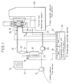
- Fig. 1 is a system diagram showing one embodiment of the temperature control method and apparatus therefor according to the present invention.
- Fig. 2 is a system diagram showing in detail the functions of the temperature controller section.
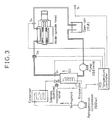
- Fig. 3 is a system diagram showing the flow path of an experimental apparatus in an experimental example.
- FIG. 1 is a system diagram showing one example of a temperature control apparatus for a machine tool on which the temperature control method of the present invention is carried out. An outline of the arrangement of the temperature control apparatus will first be explained with reference to Fig. 1.
- the figure shows a temperature control apparatus for a spindle head 41 of a machining center 40.
- the temperature control apparatus generally comprises a cooling medium flow section 1, a heat transfer medium flow section 2 and a temperature controller section 3.
- oil cooling oil
- a refrigerant fluorocarbon
- the temperature controller section 3 directly controls the temperature of the heat transfer fluid by controlling the degree of opening of a solenoid-operated expansion valve 15 provided in a refrigerant passage 13 by proportional plus integral plus derivative action, i.e., PID action, in accordance with the quantity of heat generated (heat load) at the spindle head 41, thereby indirectly controlling the temperature of the spindle head 41.
- PID action proportional plus integral plus derivative action
- the heat transfer medium flow section 2 is arranged to pass cooling oil as being a heat transfer fluid through a jacket 25 provided inside the spindle head 41 so as to take away the heat generated at the spindle head 41 through heat exchange, thereby cooling the spindle head 41.
- the heat transfer medium flow section 2 comprises the following devices.
- a heat exchanger (evaporator) 10 cools the cooling oil heated by taking away the heat generated at the spindle head 41.
- the cooling is effected by performing heat exchange between the heated cooling oil and the refrigerant flowing through the cooling medium passage 13, thereby cooling the oil to a set temperature.
- the heat transfer medium flow section 2 further comprises a cooling oil pump 20 for circulating the cooling oil, a damping tank 22 and cooling oil pipes 21, 23, 24, 26 and 27.
- the damping tank 22 is provided for the purpose of increasing the time constant of a sensor S3 for detecting the oil temperature at the spindle head inlet for the reason described later.
- the time constant of the sensor S3 may be made greater than that of a sensor S2 by bringing the sensor S3 into contact with the wall of the passage or placing in the passage the sensor S3 which is put in a sheath having a proper time constant instead of providing the damping tank 22.
- a sensor which has a large time constant may also be employed.
- the spindle head 41 To effect heat exchange between a machine tool and a heat transfer fluid, it is possible in the case of the spindle head 41 to employ a method wherein the jacket 25, which is a space, is provided as in the case of this embodiment or a method wherein cooling oil is showered on the inner wall surface of the spindle head 41 and this cooling oil is collected and discharged out of the spindle head 41.
- the cooling medium passage 1 is the same as the ordinary refrigerating circuit.
- a solenoid-operated expansion valve 15 which is capable of automatically controlling the flow rate of the refrigerant by force is employed as a means that functions as an expansion valve or a capillary tube.
- the arrangement may also be such that a capillary tube is employed in place of the solenoid-operated expansion valve 15 and a solenoidoperated evaporation pressure control valve is provided at the outlet of the heat exchanger (evaporator) 10 to control the flow rate of the refrigerant.
- the temperature controller section 3 has four sensors S1 to S4 which are disposed as temperature detectors for detecting a reference temperature ⁇ 1 (room temperature or machine body temperature), the oil temperature ⁇ 2 at the outlet of the heat exchanger 10, the oil temperature ⁇ 3 at the inlet 24 of the spindle head 41 and the oil temperature ⁇ 4 at the outlet 26 of the spindle head 41.
- the outputs from the four sensors S1 to S4 are input to a Wheatstone bridge circuit, as shown in Fig. 2.
- the output ⁇ E(V) obtained at the detecting terminals may be expressed from the equation (well-known) used in the calculation for the bridge circuit as follows: wherein R: the resistance ( ⁇ ) of the fixed resistance; R1: the resistance ( ⁇ ) of a potentiometer VR1 connected to the sensor S1 for detecting the reference temperature; R4: the resistance ( ⁇ ) of a potentiometer VR2 connected to the sensor S4 for detecting the fluid temperature at the outlet of the machine tool; ⁇ 1: the temperature ( o C) detected by the sensor S1; ⁇ 2: the temperature ( o C) detected by the sensor S2; ⁇ 3: the temperature ( o C) detected by the sensor S3; ⁇ 4: the temperature ( o C) detected by the sensor S4; and ⁇ : the temperature coefficient (1/ o C) of the sensor resistance.
- numerator and denominator of the equation (4) are divided by [R+R 0 (1+ ⁇ 2)] , the terms in the numerator of the equation (4) are as follows:
- An input processing unit 31 takes in as input signals th values that are respectively obtained in the sensors S1 to S4 by converting temperatures into electric signals as described above, and the input processing unit 31 electrically processes these four signals and outputs a difference between a set point and a controlled variable.
- the voltage output ⁇ E representing the deviation is taken out in the form of an analog voltage, and after the noise component is removed in a CR filter 52, it is amplified by a DC amplifier unit 53 to a input level for control in the PID temperature control unit 32.
- the PID temperature control unit 32 performs a proportional plus integral plus derivative (PID) action so that the amplified deviation input signal becomes 0 (zero), as described above. Since this PID action is the action of a well-known control circuit which performs a control action by which the system is stabilized most promptly when there is a disturbance or a change in the set point, the circuit and the action thereof are not disclosed herein.
- the output of the PID temperature control unit 32 is input to a control output control unit 33.
- the control output control unit 33 is an output amplifier circuit which amplifies the output of the PID temperature control unit 32 to a signal level with which the solenoid-operated expansion valve 15 can be actuated and then delivers an output in the form of an output voltage or an output current.
- Figs. 1 and 2 The temperature control action according to the present invention will next be explained with reference to Figs. 1 and 2. It is assumed that, in Fig. 1, the quantity of heat generated at the spindle head 41 increases and consequently the heat load with respect to the heat transfer oil increases. The rise in the oil temperature as a result of an increase in the heat load is immediately detected by the sensor S4 and a cooling operation is initiated. More specifically, the amount of fluorocarbon flowing through the heat exchanger is increased to lower the oil temperature.
- the lowering in the oil temperature is detected by the sensor S2 at the output of the heat exchanger 10 to make a correction without delay; therefore, the transient deviation is minimized and hence the settling time is shortened. Since in the prior art system the lowering in the oil temperature caused by the cooling operation is detected by the sensor S4 to make a correction, there is a time delay and therefore the overshoot of temperature, that is, the transient deviation, increases.
- the output of the sensor S3 among the sensors eventually coincides with the output value of the sensor S2 after a certain period of time has passed. Accordingly, it is not always necessary to provide the sensor S3, provided that a substitute means, for example, a compensating circuit, which performs the same function as that of the sensor S3 is employed. More specifically, it is possible to employ a method wherein a value which changes with time in accordance with the output value of the sensor S2 is artificially produced by a microcomputer according to software or by a compensating circuit as being a hardware means to thereby effect a control action in the same way as in the case of the above-described operating principle.
- This method also makes it possible to obtain advantageous effects similar to those in the foregoing embodiment.
- the method enables the time constant of the sensor to be readily varied in accordance with the characteristics and heating capacity of the machine tool.
- oil is employed as a heat transfer fluid
- other substitutes for example, a cutting fluid, water, gas, etc.
- the temperature controller also, although the foregoing embodiment employs a PID controller, it is also possible to employ a multi-position ON-OFF action temperature controller which enables multi-stage setting, that is, which is capable of stepwise control of the flow rate of a cooling medium.
- a solenoid-operated expansion valve is employed as an actuator which varies the flow rate of the cooling medium
- a solenoid-operated evaporation pressure control valve which controls the flow rate of the low-pressure refrigerant gas at the outlet of the evaporator on the basis of a differential pressure.
- a method wherein the number of revolutions of the refrigerating machine is controlled by use of an inverter.
- the above-described temperature controller section 3 is of analog type, it may be a control apparatus which processes signals in a digital manner. For example, it is possible to employ a method wherein duty control is effected using the period of time during which the solenoid-operated expansion valve 15 is open.
- a bridged-T circuit which is a circuit performing the same function as that of the Wheatstone bridge circuit.
- a model spindle head which is closer to an actual one is employed as a load.
- Fig. 3 shows an experimental machine.
- the specifications of the experimental machine and the experimental conditions are as follows:
- 0.5( o C) or less is targeted for all the three deviations, that is, the transient deviation, the steady-state deviation of the oil temperature and the steady-state deviation of the machine body.
- the steady-state deviation of the machine body is small, i.e., 0.15( o C)
- the steady-state deviation of the oil temperature is -0.05( o C)
- the transient deviation ⁇ is large, i.e., 1.24 ( o C).
- the steady-state deviation of the oil temperature is 0 and the transient deviation is also small, i.e., 0.3( o C), but the steady-state deviation of the machine body is large, i.e., 2.3 ( o C).
- the steady-state deviation of the oil temperature is 0, the transient deviation is small, i.e., 0.3( o C), and the steady-state deviation of the machine body is the smallest in the three, i.e., 0.1( o C).
- the present invention is not limited to cooling of a spindle head of a machine tool such as the machining center in the embodiment.
- the present invention is applicable to various kinds of machine tool and industrial machine, for example, NC (numerically controlled) lathes, (NC) grinding machines, electric discharge machines, etc.
- NC number of machine tool and industrial machine
- NC number of machine tool and industrial machine
- the constituent element of a machine that is subjected to cooling control is not limited to a spindle head, either, and the present invention is applicable to cooling of various portions of machine tools, for example, a driving system using a ball screw, a driving motor section, a column, a bed, etc.
Landscapes
- Engineering & Computer Science (AREA)
- Physics & Mathematics (AREA)
- General Physics & Mathematics (AREA)
- Automation & Control Theory (AREA)
- Mechanical Engineering (AREA)
- Thermal Sciences (AREA)
- General Engineering & Computer Science (AREA)
- Chemical & Material Sciences (AREA)
- Combustion & Propulsion (AREA)
- Remote Sensing (AREA)
- Automatic Control Of Machine Tools (AREA)
Claims (3)
- Temperatursteuerungsvorrichtung für eine Werkzeugmaschine oder eine Industriemaschine mit einem wärmeerzeugenden Bestandteil, mit:- einem Wärmeübertragungsfluid, das mit dem Bestandteil (41) zu dessen Kühlung in Berührung gebracht wird;- einem Wärmetauscher (10) zur Kühlung des Wärmeübertragungsfluids mit einem Kühlmedium zur Steuerung der Temperatur des Wärmeübertragungsfluids, welcher Wärmetauscher (10) mit einem Auslaß des Bestandteils (41) verbunden ist,- einem Detektor (51) zum Ermitteln einer Temperaturdifferenz, der einen ersten Sensor (S₁) zur Abtastung einer Bezugstemperatur (ϑ₁) und einen zweiten Sensor (S₄) zur Abstastung der Temperatur (ϑ₄) des Wärmeübertragungsfluids an dem Auslaß des Bestandteils (41) umfaßt wobei der Detektor (51) zur Ermittlung der Temperaturdifferenz vorgesehen ist zur Erzeugung eines Ausgangssignals (ΔE) in Abhängigkeit von einer Differenz zwischen der Temperatur (ϑ₄) die durch den zweiten Sensor (S₄) abgetastet wird, und der Bezugstemperatur (ϑ₁); und- einer Steuereinrichtung (32), die aktiviert wird entsprechend dem Ausgangssignal (ΔE) zur Steuerung der Temperatur des Wärmeübertragungsfluids zur Aufrechterhaltung einer eingestellten Temperaturdifferenz zwischen der Temperatur (ϑ₄). die durch den zweiten Sensor (S₄) abgetastet wird, und der Bezugstemperatur (ϑ₁),dadurch gekennzeichnet, daß- der Detektor (51) zum Abtasten der Temperaturdifferenz weiterhin einen dritten Sensor (S₂) zur Abtastung der Temperatur (ϑ₂) des Wärmeübertragungsfluids am Auslaß des Wärmetauschers (10) und einen vierten Sensor (S₃) zur Abtastung der Temperatur (ϑ₃) des Wärmeübertragungsfluids am Einlaß des Bestandteils (41) umfaßt wobei der vierte Sensor (s₃) eine Zeitkonstante aufweist, die größer als diejenige des dritten Sensors (S₂) ist,- der Detektor (51) für die Temperaturdifferenz vorgesehen ist zur Erzeugung des Ausgangssignals (ΔE) in weiterer Abhängigkeit von einer Differenz zwischen der Temperatur (ϑ₂), die durch den dritten Sensor (S₂) abgetastet wird, und der Temperatur (ϑ₃) die durch den vierten Sensor (S₃) abgetastet wird, und- die Steuereinrichtung (32) vorgesehen ist zur Aufrechterhaltung der Temperatur (ϑ₂). die durch den dritten Sensor (S₂) abgetastet wird, gleich der Temperatur (ϑ₃). die durch den vierten Sensor (S₃) abgetastet wird.
- Temperatursteuervorrichtung nach Anspruch 1, dadurch gekennzeichnet, daß die Einrichtung zur Abtastung der Temperaturdifferenz eine Brückenschaltung (51) ist, die alle Sensoren (S₁-S₄) einschließt, und daß die Steuereinrichtung gebildet ist durch eine PID-Schaltung (32), die eine proportionale plus integrale plus abgeleitete Arbeitsweise aufweist.
- Temperatursteuervorrichtung nach Anspruch 1 oder 2, dadurch gekennzeichnet, daß ein Dämpfungstank (22) zur Erhöhung der Zeitkonstanten des vierten Sensors (S₃) in einem Wärmeübertragungs-Fluidkanal (23) zwischen dem Auslaß des Wärmetauschers (10) und dem Eingang des Bestandteils (41) vorgesehen ist.
Applications Claiming Priority (3)
| Application Number | Priority Date | Filing Date | Title |
|---|---|---|---|
| JP150054/88 | 1988-06-20 | ||
| JP15005488 | 1988-06-20 | ||
| PCT/JP1989/000553 WO1989012527A1 (en) | 1988-06-20 | 1989-06-01 | Method of controlling temperature of machine tool and apparatus for practicing same |
Publications (3)
| Publication Number | Publication Date |
|---|---|
| EP0409989A1 EP0409989A1 (de) | 1991-01-30 |
| EP0409989A4 EP0409989A4 (en) | 1991-12-11 |
| EP0409989B1 true EP0409989B1 (de) | 1994-08-24 |
Family
ID=15488499
Family Applications (1)
| Application Number | Title | Priority Date | Filing Date |
|---|---|---|---|
| EP89906449A Expired - Lifetime EP0409989B1 (de) | 1988-06-20 | 1989-06-01 | Verfahren zur regelung der temperatur eines werkzeugs und vorrichtung dazu |
Country Status (4)
| Country | Link |
|---|---|
| US (1) | US5197537A (de) |
| EP (1) | EP0409989B1 (de) |
| DE (1) | DE68917724T2 (de) |
| WO (1) | WO1989012527A1 (de) |
Cited By (1)
| Publication number | Priority date | Publication date | Assignee | Title |
|---|---|---|---|---|
| DE10028517B4 (de) * | 1999-07-08 | 2015-11-12 | Smc Corp. | Thermostatische Kühlflüssigkeitszirkuliervorrichtung |
Families Citing this family (34)
| Publication number | Priority date | Publication date | Assignee | Title |
|---|---|---|---|---|
| JPH05253790A (ja) * | 1992-03-13 | 1993-10-05 | Toshiba Mach Co Ltd | 工作機械の超精密温度制御システム及びその制御方法 |
| US5582237A (en) * | 1994-01-11 | 1996-12-10 | Miyano; Toshiharu | Apparatus for preventing thermal deformation of a machine tool |
| EP0663263B1 (de) * | 1994-01-14 | 1996-12-18 | Miyano, Toshiharu Tom | Anlage zum Vermeiden von thermischen Verformungen einer Werkzeugmaschine |
| CN1062800C (zh) * | 1994-01-22 | 2001-03-07 | 宫野利治 | 工具机热变形的防止装置 |
| CH690065A5 (fr) * | 1994-09-14 | 2000-04-14 | Willy Rothen | Procédé de fixation de pièces par congélation et dispositif pour la mise en oeuvre du procédé. |
| DE4440380A1 (de) * | 1994-11-11 | 1996-05-15 | Baldwin Gegenheimer Gmbh | Geräteschrank zur Bereitstellung von Prozeßwasser |
| US5606870A (en) * | 1995-02-10 | 1997-03-04 | Redstone Engineering | Low-temperature refrigeration system with precise temperature control |
| US5873253A (en) * | 1997-04-03 | 1999-02-23 | Camphous; Catherine M. | Method and apparatus for cooling parts that are being worked |
| US5862675A (en) * | 1997-05-30 | 1999-01-26 | Mainstream Engineering Corporation | Electrically-driven cooling/heating system utilizing circulated liquid |
| EP0949550A1 (de) * | 1998-04-09 | 1999-10-13 | Marksa SA | Numerische Steuerung Werkzeugmaschine und Verfahren um diese Maschine zu kühlen |
| US6164557A (en) * | 1998-04-30 | 2000-12-26 | Sioux Steam Cleaner Corporation | Fluid temperature control for a heated fluid cleaner with multiple outlets |
| FR2784918B1 (fr) * | 1998-10-21 | 2000-12-01 | Service Et Tech Mace Thierry | Dispositif de refroidissement de l'huile de coupe d'une machine-outil |
| US6089797A (en) * | 1998-11-30 | 2000-07-18 | Excellon Automation, Co. | Thermal equalization system |
| US6352106B1 (en) * | 1999-05-07 | 2002-03-05 | Thomas B. Hartman | High-efficiency pumping and distribution system incorporating a self-balancing, modulating control valve |
| US6212895B1 (en) | 1999-11-19 | 2001-04-10 | Emmpak Foods Inc. | Machinery cooling system |
| DE10000331C2 (de) * | 2000-01-07 | 2001-12-13 | Loh Kg Rittal Werk | Kühleinrichtung |
| US6334331B1 (en) * | 2000-06-01 | 2002-01-01 | Taiwan Semiconductor Manufacturing Company, Ltd | Uninterrupted sub-loop water cooling system equipped with buffer tank |
| US6886361B2 (en) * | 2000-06-28 | 2005-05-03 | Igc-Polycold Systems, Inc. | Liquid chiller evaporator |
| US6418748B1 (en) | 2001-03-22 | 2002-07-16 | Emmpak Foods, Inc. | Machinery cooling system |
| CN1265137C (zh) * | 2001-05-03 | 2006-07-19 | 马特斯·林德格伦 | 用于控制从热交换器流出的输出流的温度并测量所产生的热量的方法和装置 |
| DE102005024743B3 (de) * | 2005-05-31 | 2006-09-28 | Hydac System Gmbh | Temperiervorrichtung |
| US7568275B2 (en) * | 2006-11-13 | 2009-08-04 | Jensen Robert M | Apparatus, systems and methods for work piece isothermal dry machining and assembly fixtures |
| KR100830095B1 (ko) * | 2007-11-12 | 2008-05-20 | 충남대학교산학협력단 | 냉방부하 예측방법 |
| DE102011017433C5 (de) * | 2011-04-18 | 2018-02-15 | Compair Drucklufttechnik Zweigniederlassung Der Gardner Denver Deutschland Gmbh | Verfahren zur intelligenten Regelung einer Kompressoranlage mit einer Wärmerückgewinnung |
| EP2999442B1 (de) | 2013-05-20 | 2021-04-07 | Stryker Corporation | Wärmesteuerungssystem |
| EP2878912B1 (de) * | 2013-11-28 | 2016-08-24 | Alfa Laval Corporate AB | System und Verfahren zur dynamischen Steuerung eines Wärmetauschers |
| US20150285264A1 (en) * | 2014-04-07 | 2015-10-08 | Union Pacific Railroad Company | Air compressor with self contained cooling system |
| TWM498082U (zh) * | 2014-04-15 | 2015-04-01 | Accutex Technologies Co Ltd | 工具機之加工液冷卻系統 |
| US11058572B2 (en) | 2016-10-11 | 2021-07-13 | Stryker Corporation | Thermal control system |
| IT201700061222A1 (it) * | 2017-06-05 | 2018-12-05 | Breton Spa | Macchina utensile e metodo per il controllo di variazioni di temperatura in una macchina utensile. |
| TWI628035B (zh) | 2017-08-09 | 2018-07-01 | 財團法人工業技術研究院 | 熱穩定控制系統與方法 |
| TWI656939B (zh) | 2018-08-15 | 2019-04-21 | 財團法人工業技術研究院 | 溫度控制系統及其方法 |
| CN109373799A (zh) * | 2018-12-20 | 2019-02-22 | 江苏道明化学有限公司 | 一种冷却塔风机控制系统的控制方法 |
| JP7427326B2 (ja) * | 2019-08-26 | 2024-02-05 | 株式会社ディスコ | 定温水供給装置 |
Family Cites Families (13)
| Publication number | Priority date | Publication date | Assignee | Title |
|---|---|---|---|---|
| US2606747A (en) * | 1948-11-02 | 1952-08-12 | Chrysler Corp | Temperature control apparatus for machine |
| US3066578A (en) * | 1958-12-17 | 1962-12-04 | Cincinnati Milling Machine Co | Temperature control of machine tool |
| US3315892A (en) * | 1964-02-07 | 1967-04-25 | Haake Peter | Method of measuring the temperature prevailing in a bath and a system for maintaining a predetermined temperature within an article |
| US3480076A (en) * | 1966-12-29 | 1969-11-25 | Tamaki Tomita | Oil temperature control system |
| CH500539A (it) * | 1968-05-11 | 1970-12-15 | Coster Tec Elettron | Circuito per il controllo automatico della temperatura in impianti di riscaldamento o condizionamento |
| US3772896A (en) * | 1972-03-02 | 1973-11-20 | Fluidics Inc | Heat exchange unit to regulate the temperature of recirculating hydraulic fluid for operating hydraulic systems of machinery |
| US3859812A (en) * | 1974-03-08 | 1975-01-14 | Richard B Pavlak | Methods and apparatus for treating machine tool coolants |
| US4060997A (en) * | 1976-03-31 | 1977-12-06 | Application Engineering Corporation | Water chiller control |
| JPS6045040B2 (ja) * | 1980-05-19 | 1985-10-07 | 株式会社 アマダ | プレスのフレ−ムの熱変形を制御する方法および装置 |
| JPS6244351A (ja) * | 1985-08-23 | 1987-02-26 | Hitachi Ltd | 工作機械の主軸冷却制御装置 |
| GB8615576D0 (en) * | 1986-06-23 | 1986-07-30 | Rees J E | Removing heat from hydraulic circuits |
| JPS6366781A (ja) * | 1986-09-08 | 1988-03-25 | Hitachi Maxell Ltd | デイスクカ−トリツジ |
| JPH0728545Y2 (ja) * | 1986-10-18 | 1995-06-28 | ダイキン工業株式会社 | 液体温度制御装置 |
-
1989
- 1989-06-01 EP EP89906449A patent/EP0409989B1/de not_active Expired - Lifetime
- 1989-06-01 US US07/423,469 patent/US5197537A/en not_active Expired - Lifetime
- 1989-06-01 DE DE68917724T patent/DE68917724T2/de not_active Expired - Lifetime
- 1989-06-01 WO PCT/JP1989/000553 patent/WO1989012527A1/ja not_active Ceased
Cited By (1)
| Publication number | Priority date | Publication date | Assignee | Title |
|---|---|---|---|---|
| DE10028517B4 (de) * | 1999-07-08 | 2015-11-12 | Smc Corp. | Thermostatische Kühlflüssigkeitszirkuliervorrichtung |
Also Published As
| Publication number | Publication date |
|---|---|
| EP0409989A4 (en) | 1991-12-11 |
| DE68917724T2 (de) | 1994-12-15 |
| EP0409989A1 (de) | 1991-01-30 |
| US5197537A (en) | 1993-03-30 |
| WO1989012527A1 (en) | 1989-12-28 |
| DE68917724D1 (de) | 1994-09-29 |
Similar Documents
| Publication | Publication Date | Title |
|---|---|---|
| EP0409989B1 (de) | Verfahren zur regelung der temperatur eines werkzeugs und vorrichtung dazu | |
| US4523435A (en) | Method and apparatus for controlling a refrigerant expansion valve in a refrigeration system | |
| EP0730128B1 (de) | Fuzzylogikregelung der Zuführung einer Flüssigkeit für die Kühlung eines Motors | |
| US5476137A (en) | Ultra-precision temperature control system for machine tool and control method therefor | |
| US4487028A (en) | Control for a variable capacity temperature conditioning system | |
| EP0158581B1 (de) | Verfahren und Regelvorrichtung zum Schützen eines Verdampfers in einem Kühlsystem gegen Zufrieren | |
| WO1999008002A1 (en) | Compressor minimum capacity control | |
| JPH0541904B2 (de) | ||
| US4498310A (en) | Heat pump system | |
| EP0347821A2 (de) | Temperatursteuergerät für Flüssigkeitskühlungssysteme | |
| EP1851491B1 (de) | Kompressorsystem mit gesteuerter schmiermittelrückgewinnung | |
| US4948950A (en) | Heating system, control device therefor and methods of making the same | |
| KR900006223B1 (ko) | 방전 가공 장치 | |
| CN101887275B (zh) | 高精度温度控制方法 | |
| KR100343695B1 (ko) | 흡수식냉동기의제어장치 | |
| JPH0825125B2 (ja) | 工作機械の温度制御方法及びその装置 | |
| JPH04372328A (ja) | 工作機械の温度制御方法 | |
| JPH0677894B2 (ja) | 工作機械の温度制御装置 | |
| JPWO1989012527A1 (ja) | 工作機械の温度制御装置 | |
| JPH0335060B2 (de) | ||
| JPH0579458B2 (de) | ||
| JP2001074318A (ja) | 冷却装置の制御方法 | |
| US4620883A (en) | Fluidized-bed heat-treatment method for metallic workpieces | |
| JPH024165A (ja) | 液体冷却装置の温度制御装置 | |
| JP3407215B2 (ja) | 温調装置の温度制御方法 |
Legal Events
| Date | Code | Title | Description |
|---|---|---|---|
| PUAI | Public reference made under article 153(3) epc to a published international application that has entered the european phase |
Free format text: ORIGINAL CODE: 0009012 |
|
| 17P | Request for examination filed |
Effective date: 19900315 |
|
| AK | Designated contracting states |
Kind code of ref document: A1 Designated state(s): CH DE GB IT LI |
|
| A4 | Supplementary search report drawn up and despatched |
Effective date: 19911023 |
|
| AK | Designated contracting states |
Kind code of ref document: A4 Designated state(s): CH DE GB IT LI |
|
| 17Q | First examination report despatched |
Effective date: 19930122 |
|
| GRAA | (expected) grant |
Free format text: ORIGINAL CODE: 0009210 |
|
| ITF | It: translation for a ep patent filed | ||
| AK | Designated contracting states |
Kind code of ref document: B1 Designated state(s): CH DE GB IT LI |
|
| REF | Corresponds to: |
Ref document number: 68917724 Country of ref document: DE Date of ref document: 19940929 |
|
| PLBE | No opposition filed within time limit |
Free format text: ORIGINAL CODE: 0009261 |
|
| STAA | Information on the status of an ep patent application or granted ep patent |
Free format text: STATUS: NO OPPOSITION FILED WITHIN TIME LIMIT |
|
| 26N | No opposition filed | ||
| REG | Reference to a national code |
Ref country code: GB Ref legal event code: IF02 |
|
| PGFP | Annual fee paid to national office [announced via postgrant information from national office to epo] |
Ref country code: GB Payment date: 20020524 Year of fee payment: 14 |
|
| PG25 | Lapsed in a contracting state [announced via postgrant information from national office to epo] |
Ref country code: GB Free format text: LAPSE BECAUSE OF NON-PAYMENT OF DUE FEES Effective date: 20030601 |
|
| GBPC | Gb: european patent ceased through non-payment of renewal fee |
Effective date: 20030601 |
|
| PG25 | Lapsed in a contracting state [announced via postgrant information from national office to epo] |
Ref country code: IT Free format text: LAPSE BECAUSE OF NON-PAYMENT OF DUE FEES;WARNING: LAPSES OF ITALIAN PATENTS WITH EFFECTIVE DATE BEFORE 2007 MAY HAVE OCCURRED AT ANY TIME BEFORE 2007. THE CORRECT EFFECTIVE DATE MAY BE DIFFERENT FROM THE ONE RECORDED. Effective date: 20050601 |
|
| PGFP | Annual fee paid to national office [announced via postgrant information from national office to epo] |
Ref country code: CH Payment date: 20080618 Year of fee payment: 20 |
|
| PGFP | Annual fee paid to national office [announced via postgrant information from national office to epo] |
Ref country code: DE Payment date: 20080626 Year of fee payment: 20 |
|
| REG | Reference to a national code |
Ref country code: CH Ref legal event code: PL |