EP0663586A1 - Gasströmungs- und Temperatursonde, Gasströmungs- und Temperaturüberwachungssystem mit einer oder mehreren solchen Sonden - Google Patents
Gasströmungs- und Temperatursonde, Gasströmungs- und Temperaturüberwachungssystem mit einer oder mehreren solchen Sonden Download PDFInfo
- Publication number
- EP0663586A1 EP0663586A1 EP95300112A EP95300112A EP0663586A1 EP 0663586 A1 EP0663586 A1 EP 0663586A1 EP 95300112 A EP95300112 A EP 95300112A EP 95300112 A EP95300112 A EP 95300112A EP 0663586 A1 EP0663586 A1 EP 0663586A1
- Authority
- EP
- European Patent Office
- Prior art keywords
- temperature
- gas flow
- circuit
- probe
- cooling rate
- Prior art date
- Legal status (The legal status is an assumption and is not a legal conclusion. Google has not performed a legal analysis and makes no representation as to the accuracy of the status listed.)
- Withdrawn
Links
- 239000000523 sample Substances 0.000 title claims abstract description 77
- 238000001816 cooling Methods 0.000 claims abstract description 41
- 238000005070 sampling Methods 0.000 claims abstract description 10
- 238000005259 measurement Methods 0.000 description 10
- 238000000034 method Methods 0.000 description 4
- 239000004809 Teflon Substances 0.000 description 2
- 229920006362 Teflon® Polymers 0.000 description 2
- 238000009529 body temperature measurement Methods 0.000 description 2
- 239000002775 capsule Substances 0.000 description 2
- 230000008859 change Effects 0.000 description 2
- 230000000694 effects Effects 0.000 description 2
- 230000006870 function Effects 0.000 description 2
- 230000000295 complement effect Effects 0.000 description 1
- 238000010586 diagram Methods 0.000 description 1
- 238000005553 drilling Methods 0.000 description 1
- 238000012544 monitoring process Methods 0.000 description 1
- 230000008569 process Effects 0.000 description 1
- 230000003252 repetitive effect Effects 0.000 description 1
- 230000004044 response Effects 0.000 description 1
Images
Classifications
-
- G—PHYSICS
- G01—MEASURING; TESTING
- G01F—MEASURING VOLUME, VOLUME FLOW, MASS FLOW OR LIQUID LEVEL; METERING BY VOLUME
- G01F1/00—Measuring the volume flow or mass flow of fluid or fluent solid material wherein the fluid passes through a meter in a continuous flow
- G01F1/68—Measuring the volume flow or mass flow of fluid or fluent solid material wherein the fluid passes through a meter in a continuous flow by using thermal effects
- G01F1/696—Circuits therefor, e.g. constant-current flow meters
-
- G—PHYSICS
- G01—MEASURING; TESTING
- G01F—MEASURING VOLUME, VOLUME FLOW, MASS FLOW OR LIQUID LEVEL; METERING BY VOLUME
- G01F25/00—Testing or calibration of apparatus for measuring volume, volume flow or liquid level or for metering by volume
- G01F25/10—Testing or calibration of apparatus for measuring volume, volume flow or liquid level or for metering by volume of flowmeters
-
- G—PHYSICS
- G01—MEASURING; TESTING
- G01F—MEASURING VOLUME, VOLUME FLOW, MASS FLOW OR LIQUID LEVEL; METERING BY VOLUME
- G01F1/00—Measuring the volume flow or mass flow of fluid or fluent solid material wherein the fluid passes through a meter in a continuous flow
- G01F1/68—Measuring the volume flow or mass flow of fluid or fluent solid material wherein the fluid passes through a meter in a continuous flow by using thermal effects
- G01F1/696—Circuits therefor, e.g. constant-current flow meters
- G01F1/6965—Circuits therefor, e.g. constant-current flow meters comprising means to store calibration data for flow signal calculation or correction
Definitions
- This invention relates to an improved gas flow and temperature probe and an improved multipoint gas flow and temperature sensing system utilizing a plurality of such probes to measure gas cooling rate, temperature, and ultimately gas flow and linear gas velocity.
- the gas flow and temperature measurements need to be taken at several locations virtually simultaneously.
- the gas typically air
- temperature and temperature measurements are required at different locations in the system at different locations on the printed circuit boards. This has to be done to make sure that the components are getting needed airflow so that they can get cooled to the required temperature.
- a standard single probe presently available has a telescopic body with the probe at the tip. Introduction of this probe causes the flow field to change because of the physical size and shape of the probe disturbs the airflow. Also this probe requires a straight line access to the location of measurement due to the rigid body of the probe. This restricts the measurability of several locations in an environment. For example, a cabinet with several electronic boards has little space for a straight probe to access the location on a board between two devices.
- the individual probes must be carefully fabricated using expensive, high-precision components or elaborate calibrating techniques to insure that each of the probes presents the same form of input to the signal processor host and can be interchanged without special adjustment.
- the invention results from the realization that a truly non-intrusive, interchangeable gas flow and temperature probe which facilitates easy access to even difficult locations can be achieved using a small sensor connected over a long, flexible, small cross-section area cable to a remote but in-line prenormalizing circuit which provides the sensed cooling rate temperature and rate signals along with calibration data characterizing the response of the particular probe sensor and circuitry to a normalizing circuit which standardizes the output of each probe.
- This invention features a gas flow temperature probe including sensor means for sensing the ambient gas cooling rate and temperature and a prenormalizer circuit responsive to and remote from the sensor means for detecting gas cooling rate and temperature signals from the sensor means and for providing calibration data unique to the probe for normalizing the detected gas cooling rate and temperature to generate a normalized gas flow and temperature sensed by the probe.
- Elongated flexible cable means interconnects the sensor means and the prenormalizer circuit for transmitting the ambient gas cooling rate and temperature signals from the sensor means to the prenormalizer circuit.
- the sensor means may include a cooling rate sensor and a temperature sensor.
- the cable may have a cross-sectional area of less than approximately 0.03 in2.
- the cable may be flat and may be approximately 0.1 inch wide and 0.025 inch thick.
- the sensor means may be less than one inch long and .5 inch wide and .01 inch thick.
- the sensor means may be approximately .5 inch long, 0.2 inch wide and .03 inch thick.
- the gas whose cooling rate and temperature is being sensed may be air.
- the prenormalizer circuit may be disposed in line with the cable means and may further include an output connector and an output cable interconnecting the output connector and the prenormalizer circuit.
- the invention also features a multiplexer gas flow and temperature sensing system which includes a plurality of gas flow and temperature probes each having sensor means for sensing the ambient gas temperature and cooling rate and a prenormalizer circuit responsive to and remote from the sensor means for detecting gas cooling rate and temperature signals from the sensor means and for providing calibration data unique to the probe for normalizing the detected gas cooling rate and temperature to generate a normalized gas flow and temperature sensed by the probe.
- An elongated flexible cable means interconnects the sensor means and the prenormalizer circuit for transmitting the ambient gas cooling rate and temperature signals from the sensor means to the prenormalizer circuit.
- a gas flow and temperature monitor circuit includes a multiplexer circuit for real time sampling of the probes, a scheduler circuit for defining the sampling rate, and a normalizer circuit for combining the gas cooling rate and temperature signals and the calibration data from the prenormalizer circuit for each probe for generating the normalized gas flow and temperature sensed by each probe.
- the gas flow and temperature monitor may include a gas density sensor and the normalizer circuit may further include means for calculating the linear gas velocity from the gas flow and the sensed density.
- This invention may be accomplished with a gas flow and temperature probe that includes a sensor means for sensing the ambient gas cooling rate and temperature.
- the ambient gas may be and typically is air in electronic environments.
- the sensor is made small with a low profile so that it is virtually non-invasive or non-intrusive with respect to the air flow in which it is located and measures.
- the sensor means may include a cooling rate sensor such as a thermistor and a separate temperature sensor, or it may include a single element which is alternately switched back and forth to perform each of those functions selectively.
- the sensor is less than an inch long, a half inch wide, and one tenth of an inch thick. In one particular embodiment the entire sensor is but one half inch long, two tenths of an inch wide, and three hundredths of an inch thick.
- a prenormalizer circuit responsive to and remote from the sensor device detects the gas temperature and cooling rate signals from the sensor device and provides calibration data unique to the probe for normalizing the detected gas cooling rate and temperature from which subsequently can be generated a normalized gas flow and temperature as sensed by the probe.
- the prenormalizer circuit receives the signals from the sensor device and converts them to an electrical signal which is supplied along with the calibration data to a normalizer circuit in a gas flow and temperature monitor.
- the calibration data is typically stored in the non-volatile memory and is placed there by empirically exposing the sensor means to known flow rates and recording the velocity and temperature at three different known flow rates to obtain data for three simultaneous equations that can be solved to obtain the three constants K0, K1 and K2 which are stored as the calibration data in the prenormalizer circuit associated with each probe.
- the cable typically has a cross-sectional area of less than .03 in2, but may be larger or smaller, provided only that it has minimal effect on the air flow in which it resides.
- the cable means may be a conventional flat Teflon cable approximately .1 inch wide and .025 inch thick.
- a complete multipoint gas flow and temperature sensing system may be constructed using a plurality of such probes and a gas flow and temperature monitor circuit which includes a multiplexer circuit for real time sampling of the pulses.
- the multiplexer sampling time is so fast compared to the time scale of the air flow and temperature that the multipoint sensing is accomplished essentially simultaneously.
- the gas flow and temperature monitor may include a gas density sensor and the normalizer circuit may include means for calculating the linear gas velocity from the gas flow and the gas density.
- the cable may be as long as six feet or longer and the prenormalizer circuit is disposed in line with the cable and may be housed in a cylinder three inches or less long and approximately one half inch in diameter.
- the end of the prenormalizer circuit opposite the sensor means may use the same type of cable or another conventional cable with a pin connector at its distal end for interconnection with the gas flow and temperature monitor circuit.
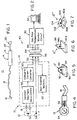
- a gas flow and temperature probe 10 including a sensor device 12 interconnected by means of an elongated flexible cable 18 with a prenormalizer circuit 14 enclosed in cylindrical capsule 16.
- the output from prenormalizer circuit 14 is interconnected with a conventional pin connector 20 by means of a cable 22 which may be similar to cable 18 but may be any kind of conventional cable as well.
- a device 12 is made small so that it may be easily placed at any desired location on the electronic equipment or other equipment and has a generally low profile so that there is little or no interference with the air flow in the area.
- the sensor is less than an inch long and 0.5 inch wide and less than 0.1 inch thick.
- Cable 18 may typically be a flat Teflon cable running as much as six feet or more in length and having a width of approximately 0.1 inch and a thickness of approximately .025 inch, although any cross-sectional shape may be used so long as it minimizes interference with the air flow in the area. Typically the cable has a cross-sectional area of less than .03 in2.
- the flexibility of cable 18 is essential in permitting the probe to be installed easily, quickly, without special handling, drilling or adjustment of the equipment, and is an important feature of this invention.
- Cylindrical capsule 16 may be three inches or less in length and 0.5 inch or less in diameter; it need not be cylindrical. It should be located in line in the cable and remote from the sensor device in order to minimize any interference with air flow in the area of the sensor device.
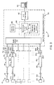
- Probe 10 is shown in greater detail in Fig. 2 interconnected with gas flow and temperature monitor circuit 30, which together constitute a multipoint gas flow and temperature sensing system 40.
- the output of gas flow and temperature monitor circuit 30 may be connected with a conventional computer 50 such as a PC.
- Sensing device 12 may include a thermistor 52 for sensing the cooling rate and a temperature sensor 54 for sensing the temperature of the air or other gas in the environment.
- the temperature signal sensed by sensor 54 is delivered over cable 18 to prenormalizer circuit 14 and from there over cable 22 to output connector 56.
- Gas flow and temperature monitoring circuit 30 is interconnected with the connector 56 from prenormalizer circuit 14 by means of complementary ten-pin connector 64 which may be connected through cable 66 or connected directly to gas flow and temperature monitor circuit 30.
- the cooling rate signal from thermistor 52 is delivered to a constant resistance/temperature servo control circuit 58 which provide the signal to voltage to current converter 60 that is in turn delivered over output cable 22 to output connector 56 which is typically a ten-pin connector.
- a constant resistance/temperature servo control circuit 58 Stored in non-volatile memory 62 in prenormalizer circuit 14 is the gas (air) flow calibration data for this particular probe 10.
- the three calibration constants K0, K1 and K2 can be determined for this particular probe.
- the temperature T being obtained from sensor 54
- the cooling rate voltage V being obtained from thermistor 52
- the actual airflow can be calculated by the gas flow and temperature monitor circuit 30.
- Gas (air) flow and temperature system 40 is shown in greater detail in Fig. 3, where the gas flow and temperature monitor circuit 30 is shown to include multiplexer 70 which has connected to it a plurality of probes 10, 10a, . . .10n.
- Normalizer circuit 80 which may utilize a conventional microprocessor, carries out the calculation for gas (air) flow as set forth in Equation (1) above utilizing the calibration data from memory 62 and the temperature signal from temperature sensor 54 and the cooling rate signal from thermistor 52 in Fig. 2. This output is provided through I/O interface 82 to, for example, conventional PC computer 50 which may be implemented by a conventional microprocessor program to carry out the calculation of gas (air) flow in accordance with Equation (1) above.
- Sampling scheduler circuit 84 may be implemented in the same microprocessor as normalizer circuit 84 as indicated by the dashed lines 86.
- a density sensor 88 for sensing the density of air or other gas being measured may be used to provide the ambient gas (air) density which is ratioed with the gas (air) density of the air or other gas at mean sea level and multiplied times the air flow from equation (1) above to obtain the linear air velocity in accordance with equation (2).
- Linear Air Velocity Air Flow (Density/Measured Density @ MSL)
- sensor device 12, Fig. 4 may include thermistor 52 and temperature sensor 54 in a housing which is approximately 0.5 inch long as measured from left to right in Fig. 4, 0.2 inch wide as measured from top to bottom in Fig. 4, and approximately .03 inch thick as measured into the paper in Fig. 4.
- a single element 12', Fig. 5 may be used and selectively switched to function alternately as a cooling rate detector and temperature sensor.
- the physical form of the sensor device may vary as well.
- sensor device 12', Fig. 5, is formed with a base 90 and crossed hoops 92 and 94 which actually support sensor element 96.
- base 90a supports a rectangular frame 98 that carries sensor element 96a
- base 90b supports a pair of S-shaped supports 100, 102 with a bridging element 104 that supports the sensor element 96b.
Landscapes
- Physics & Mathematics (AREA)
- Fluid Mechanics (AREA)
- General Physics & Mathematics (AREA)
- Measuring Volume Flow (AREA)
- Measuring Temperature Or Quantity Of Heat (AREA)
- Testing Or Calibration Of Command Recording Devices (AREA)
Applications Claiming Priority (2)
| Application Number | Priority Date | Filing Date | Title |
|---|---|---|---|
| US182654 | 1988-04-18 | ||
| US08/182,654 US5511415A (en) | 1994-01-18 | 1994-01-18 | Gas flow and temperature probe and gas flow and temperature monitor system including one or more such probes |
Publications (1)
| Publication Number | Publication Date |
|---|---|
| EP0663586A1 true EP0663586A1 (de) | 1995-07-19 |
Family
ID=22669461
Family Applications (1)
| Application Number | Title | Priority Date | Filing Date |
|---|---|---|---|
| EP95300112A Withdrawn EP0663586A1 (de) | 1994-01-18 | 1995-01-09 | Gasströmungs- und Temperatursonde, Gasströmungs- und Temperaturüberwachungssystem mit einer oder mehreren solchen Sonden |
Country Status (2)
| Country | Link |
|---|---|
| US (2) | US5511415A (de) |
| EP (1) | EP0663586A1 (de) |
Cited By (1)
| Publication number | Priority date | Publication date | Assignee | Title |
|---|---|---|---|---|
| EP1300657A2 (de) | 2001-10-08 | 2003-04-09 | AVL List GmbH | Sensor mit einer ausserhalb angeordneten Speichereinheit |
Families Citing this family (31)
| Publication number | Priority date | Publication date | Assignee | Title |
|---|---|---|---|---|
| US5940780A (en) * | 1995-09-29 | 1999-08-17 | Advanced Thermal Solutions, Inc. | Universal transceiver |
| AU736484B2 (en) | 1997-03-28 | 2001-07-26 | Applied Biosystems, Llc | Improvements in thermal cycler for PCR |
| US6447520B1 (en) * | 2001-03-19 | 2002-09-10 | Advanced Medical Optics, Inc. | IOL insertion apparatus with IOL engagement structure and method for using same |
| US6577988B1 (en) | 2000-08-08 | 2003-06-10 | International Business Machines Corporation | Method and system for remote gas monitoring |
| US6511223B1 (en) * | 2000-11-10 | 2003-01-28 | Electronic Controls Design, Inc. | Conveyor oven profiler with simplified temperature sensor connection scheme |
| US6889346B2 (en) * | 2001-07-16 | 2005-05-03 | International Business Machines Corporation | Scoping of real time signals of remote communication systems over a computer network: systems, methods and program products |
| ES2283388T5 (es) * | 2001-10-12 | 2013-11-08 | Kistler Holding Ag | Sensor |
| US6829930B2 (en) * | 2002-05-29 | 2004-12-14 | Degree Controls, Inc. | Gas velocity and temperature sensor system |
| US6796172B2 (en) * | 2002-07-31 | 2004-09-28 | Hewlett-Packard Development Company, L.P. | Flow sensor |
| US6871535B2 (en) | 2002-08-14 | 2005-03-29 | Hewlett-Packard Development Company, L.P. | Flow direction detector |
| US6836131B2 (en) | 2002-08-16 | 2004-12-28 | Credence Systems Corp. | Spray cooling and transparent cooling plate thermal management system |
| US20040071182A1 (en) * | 2002-10-11 | 2004-04-15 | Welch Allyn, Inc. | Thermometry probe calibration method |
| US6971790B2 (en) * | 2002-10-11 | 2005-12-06 | Welch Allyn, Inc. | Thermometry probe calibration method |
| US7201033B2 (en) * | 2003-08-14 | 2007-04-10 | Fluid Components International Llc | Flowmeter in-situ calibration verification system |
| US7201049B2 (en) * | 2003-10-31 | 2007-04-10 | Degree Controls, Inc. | Pulsed thermistor sensor |
| US7481213B2 (en) * | 2004-02-11 | 2009-01-27 | Hewlett-Packard Development Company, L.P. | Medicament dispenser |
| US7467630B2 (en) * | 2004-02-11 | 2008-12-23 | Hewlett-Packard Development Company, L.P. | Medicament dispenser |
| US20060159091A1 (en) * | 2005-01-19 | 2006-07-20 | Arjen Boers | Active multicast information protocol |
| US20060266229A1 (en) * | 2005-05-24 | 2006-11-30 | Ambex, Inc. | Coffee roasting control system and process |
| US20070290702A1 (en) * | 2006-06-19 | 2007-12-20 | Credence Systems Corporation | System and method for thermal management and gradient reduction |
| US20070291361A1 (en) * | 2006-06-19 | 2007-12-20 | Credence Systems Corporation | Lens housing with integrated thermal management |
| US7785000B2 (en) * | 2007-09-11 | 2010-08-31 | Fluke Corporation | Venting system for drywell calibrators |
| US20090274192A1 (en) * | 2008-05-02 | 2009-11-05 | Chao-Man Tseng | Replaceable electronic clinical thermometer |
| AT10236U3 (de) | 2008-07-10 | 2009-09-15 | Avl List Gmbh | Messanordnung und verfahren zur erfassung von messdaten |
| EP2184589A1 (de) * | 2008-11-10 | 2010-05-12 | Sensirion AG | Verfahren und Anordnung zum Messen eines Durchflusses |
| EP2187182B1 (de) * | 2008-11-12 | 2015-08-05 | Sensirion AG | Verfahren zum Betrieb eines Durchflusssensors, der wiederholt einem thermischen und/oder chemischen Reinigungsprozess ausgesetzt ist, und Durchflussmessgerät |
| US8794829B2 (en) | 2009-12-31 | 2014-08-05 | Welch Allyn, Inc. | Temperature-measurement probe |
| EP2392902B1 (de) * | 2010-06-02 | 2017-08-09 | B Medical Systems S.à.r.l. | Sensoranordnung, Lagervorrichtung umfassend eine Sensoranordnung und Verfahren zur Kalibrierung einer solchen |
| CN105466603A (zh) * | 2015-12-07 | 2016-04-06 | 上海温尔信息科技有限公司 | 一种温度计测量温度的自动校准方法、测温探头及温度计 |
| AT517608B1 (de) * | 2016-01-21 | 2017-03-15 | Avl List Gmbh | Elektronikeinheit für ein Durchflussmessgerät |
| GB202102672D0 (en) * | 2021-02-25 | 2021-04-14 | Alba Diagnostics Ltd | Apparatus for indicating the boiling point of a fluid |
Citations (2)
| Publication number | Priority date | Publication date | Assignee | Title |
|---|---|---|---|---|
| US4733541A (en) * | 1986-09-09 | 1988-03-29 | Cambridge Aeroflo Inc. | Constant cooling circuit and system |
| US4860583A (en) * | 1988-05-27 | 1989-08-29 | Dwyer Instruments, Inc. | Air velocity transmitter device |
Family Cites Families (8)
| Publication number | Priority date | Publication date | Assignee | Title |
|---|---|---|---|---|
| US3595079A (en) * | 1967-11-13 | 1971-07-27 | Univ Northwestern | Fluid flow velocity measuring apparatus |
| US3945252A (en) * | 1975-01-30 | 1976-03-23 | William Victor Fiore | Fluid flow measuring apparatus |
| DE3302080A1 (de) * | 1983-01-22 | 1984-07-26 | Leybold-Heraeus GmbH, 5000 Köln | Thermischer massendurchflussmesser, insbesondere fuer gase |
| US4537068A (en) * | 1983-03-10 | 1985-08-27 | Dwyer Instruments, Inc. | Thermal anemometer |
| US4503707A (en) * | 1983-03-28 | 1985-03-12 | Ondyne Inc. | Hygrometry probe |
| US4548516A (en) * | 1984-12-24 | 1985-10-22 | Helenowski Tomasz K | Sequential thermography fluid flow indicator |
| JP2569978B2 (ja) * | 1991-02-26 | 1997-01-08 | 三菱電機株式会社 | 内燃機関の制御装置 |
| US5226729A (en) * | 1992-10-07 | 1993-07-13 | Lennox Industries Inc. | Averaging temperature probe |
-
1994
- 1994-01-18 US US08/182,654 patent/US5511415A/en not_active Expired - Lifetime
-
1995
- 1995-01-09 EP EP95300112A patent/EP0663586A1/de not_active Withdrawn
- 1995-12-18 US US08/572,895 patent/US5792951A/en not_active Expired - Lifetime
Patent Citations (2)
| Publication number | Priority date | Publication date | Assignee | Title |
|---|---|---|---|---|
| US4733541A (en) * | 1986-09-09 | 1988-03-29 | Cambridge Aeroflo Inc. | Constant cooling circuit and system |
| US4860583A (en) * | 1988-05-27 | 1989-08-29 | Dwyer Instruments, Inc. | Air velocity transmitter device |
Non-Patent Citations (3)
| Title |
|---|
| G. N. STEMME: "A MONOLITHIC GAS FLOW SENSOR WITH POLYIMIDE AS THERMAL INSULATOR", IEEE TRANSACTIONS ON ELECTRON DEVICES, vol. ED-33, no. 10, NEW YORK US, pages 1470 - 1474 * |
| J.T. SMITH: "REMOTE MONITORING OF THE PRESSURISED CABLE NETWORK", BRITISH TELECOMMUNICATIONS ENGINEERING, vol. 3, no. 2, LONDON GB, pages 76 - 78 * |
| MASAYOSHI ESASHI: "SENSORS BY MICROMACHINING", ELECTRONICS AND COMMUNICATIONS IN JAPAN, PART II: ELECTRONICS, vol. 74, no. 11, NEW-YORK, pages 76 - 83, XP000304665 * |
Cited By (1)
| Publication number | Priority date | Publication date | Assignee | Title |
|---|---|---|---|---|
| EP1300657A2 (de) | 2001-10-08 | 2003-04-09 | AVL List GmbH | Sensor mit einer ausserhalb angeordneten Speichereinheit |
Also Published As
| Publication number | Publication date |
|---|---|
| US5511415A (en) | 1996-04-30 |
| US5792951A (en) | 1998-08-11 |
Similar Documents
| Publication | Publication Date | Title |
|---|---|---|
| US5511415A (en) | Gas flow and temperature probe and gas flow and temperature monitor system including one or more such probes | |
| US5929333A (en) | Flow rate and direction measurement system | |
| EP0612405B1 (de) | Vorrichtung zur verbrennungslosen messung der qualität von gasförmigem brennstoff | |
| US3651694A (en) | Diagnostic means for detection of diseases exhibiting skin temperature variations | |
| US4335605A (en) | Mass flow meter | |
| Hammerschmidt et al. | New transient hot-bridge sensor to measure thermal conductivity, thermal diffusivity, and volumetric specific heat | |
| US7031871B2 (en) | Sensor assembly for determining total temperature, static temperature and Mach number | |
| JPH03191852A (ja) | 流体の熱伝導率及び比熱測定方法及び装置 | |
| KR20040002359A (ko) | 유량계의 정확도를 확인하는 방법 및 장치 | |
| US4673300A (en) | Calibrated probe for temperature measuring | |
| Ligęza | Static and dynamic parameters of hot-wire sensors in a wide range of filament diameters as a criterion for optimal sensor selection in measurement process | |
| Bill Jr et al. | The transition of plane plumes | |
| BR9600350A (pt) | Processo e dispositivo para a determinação da massa volumétrica de um gás de isolamento de um aparelho elétrico | |
| US5940780A (en) | Universal transceiver | |
| Paniagua et al. | Thermocouple probes for accurate temperature measurements in short duration facilities | |
| EP0025049B1 (de) | Wärmeübertragungsmessersystem | |
| US3382714A (en) | Heat-sensing instrument | |
| FI20195921A1 (en) | TEMPERATURE CALIBRATOR WITH ADVANCED FUNCTIONS | |
| Ligęza | Use of natural fluctuations of flow parameters for measurement of velocity vector | |
| GB1515611A (en) | Electric circuits | |
| Van Putten et al. | Multisensor microsystem for pulmonary function diagnostics | |
| US4475392A (en) | Skin friction gage for time-resolved measurements | |
| GB2256056A (en) | Temperature measuring apparatus. | |
| US4790668A (en) | Viscometric thermometer | |
| JPH07146189A (ja) | 表面熱流束計測装置 |
Legal Events
| Date | Code | Title | Description |
|---|---|---|---|
| PUAI | Public reference made under article 153(3) epc to a published international application that has entered the european phase |
Free format text: ORIGINAL CODE: 0009012 |
|
| 17P | Request for examination filed |
Effective date: 19950116 |
|
| AK | Designated contracting states |
Kind code of ref document: A1 Designated state(s): DE DK FR GB IE IT NL SE |
|
| RAP1 | Party data changed (applicant data changed or rights of an application transferred) |
Owner name: CAMBRIDGE ACCUSENSE, INC. |
|
| 17Q | First examination report despatched |
Effective date: 19990616 |
|
| STAA | Information on the status of an ep patent application or granted ep patent |
Free format text: STATUS: THE APPLICATION IS DEEMED TO BE WITHDRAWN |
|
| 18D | Application deemed to be withdrawn |
Effective date: 19991228 |