EP0663633A2 - Bistabile Betätigungsvorrichtung - Google Patents
Bistabile Betätigungsvorrichtung Download PDFInfo
- Publication number
- EP0663633A2 EP0663633A2 EP94120087A EP94120087A EP0663633A2 EP 0663633 A2 EP0663633 A2 EP 0663633A2 EP 94120087 A EP94120087 A EP 94120087A EP 94120087 A EP94120087 A EP 94120087A EP 0663633 A2 EP0663633 A2 EP 0663633A2
- Authority
- EP
- European Patent Office
- Prior art keywords
- actuator
- mobile element
- guides
- mobile
- inclined planes
- Prior art date
- Legal status (The legal status is an assumption and is not a legal conclusion. Google has not performed a legal analysis and makes no representation as to the accuracy of the status listed.)
- Granted
Links
Images


Classifications
-
- G—PHYSICS
- G05—CONTROLLING; REGULATING
- G05D—SYSTEMS FOR CONTROLLING OR REGULATING NON-ELECTRIC VARIABLES
- G05D23/00—Control of temperature
- G05D23/19—Control of temperature characterised by the use of electric means
- G05D23/1919—Control of temperature characterised by the use of electric means characterised by the type of controller
- G05D23/1921—Control of temperature characterised by the use of electric means characterised by the type of controller using a thermal motor
-
- F—MECHANICAL ENGINEERING; LIGHTING; HEATING; WEAPONS; BLASTING
- F03—MACHINES OR ENGINES FOR LIQUIDS; WIND, SPRING, OR WEIGHT MOTORS; PRODUCING MECHANICAL POWER OR A REACTIVE PROPULSIVE THRUST, NOT OTHERWISE PROVIDED FOR
- F03G—SPRING, WEIGHT, INERTIA OR LIKE MOTORS; MECHANICAL-POWER PRODUCING DEVICES OR MECHANISMS, NOT OTHERWISE PROVIDED FOR OR USING ENERGY SOURCES NOT OTHERWISE PROVIDED FOR
- F03G7/00—Mechanical-power-producing mechanisms, not otherwise provided for or using energy sources not otherwise provided for
- F03G7/06—Mechanical-power-producing mechanisms, not otherwise provided for or using energy sources not otherwise provided for using expansion or contraction of bodies due to heating, cooling, moistening, drying or the like
- F03G7/061—Mechanical-power-producing mechanisms, not otherwise provided for or using energy sources not otherwise provided for using expansion or contraction of bodies due to heating, cooling, moistening, drying or the like characterised by the actuating element
- F03G7/06112—Mechanical-power-producing mechanisms, not otherwise provided for or using energy sources not otherwise provided for using expansion or contraction of bodies due to heating, cooling, moistening, drying or the like characterised by the actuating element using the thermal expansion or contraction of enclosed fluids
- F03G7/06113—Mechanical-power-producing mechanisms, not otherwise provided for or using energy sources not otherwise provided for using expansion or contraction of bodies due to heating, cooling, moistening, drying or the like characterised by the actuating element using the thermal expansion or contraction of enclosed fluids the fluids subjected to phase change
Definitions
- the present invention relates to a bistable actuator device, i.e. an actuator device apt at assuming two states, both of which being stable, and in which the commutation between the two different states is commanded by an external intervention.
- a bistable actuator device is apt, during its first functional cycle, to reach a determined working condition and to maintain it, to then return to the previous working condition, in following a successive functional cycle; such actuator systems therefore have actuator means and means for maintaining the condition reached on termination of the first functional cycle; the actuator devices of the cited type contrast with those without means for maintaining the position when their supply is stopped (monostable actuator systems).
- Bistable actuator systems in practice are utilised for numerous applications: for example they are used for the realisation of blocking systems of the doors of electrical household appliances, so as to avoid dangerous operations for the user.
- Thermal bistable actuator systems are known, in which the maintaining of the position reached is assured by way of a couple of bimetallic elements; such known systems however lack appropriate functional control means, so that their way of operating, which is based on ambient temperature, easily results in being affected by external sources of heat.
- Electro-magnetic bistable actuator systems are also known, that however depend upon complex circuitry for controlling the polarity inversion or the electric commutation.
- Another typical problem of the known art is that of the complexity of the components making up the bistable devices, and their arrangement; for example the use of electromagnets makes the actuator devices complex, bulky and expensive.
- a further problem of known thermal or electric bistable systems is the reduced run available, together with the high forces to be used; normally, with the purpose of obtaining greater forces with devices of contained dimensions, the electric actuator means of devices in use must normally be sized for a very brief supply time; in such cases there is however the risk that accidental extended times of supply cause the destruction of the actuator device.
- the principal purpose of the invention is that of overcoming the aforementioned drawbacks and to indicate a bistable actuator device that is simple, economical and reliable in the most varied conditions of use; another purpose of the invention is that of indicating a bistable actuator that, even being of very contained dimensions, is able to originate great forces and runs, and is able to work with long or short periods of supply and/or insertion.
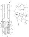
- reference number 1 indicates the bistable actuator device as a whole according to the present invention
- 2 indicates a body in which a monostable type actuator is housed
- 3 a substantially tubular shaped body is indicated within which kinematic means are housed
- the diameter of the body 3 is extremely contained (approximately 17 mm).
- a chamber 4 is defined in the body 2 which houses:
- thermoactuator 5 comprises a conductive body 8, which is thermally and electrically connected to the heater 6 supplied by two electric terminals 7.
- a sealed chamber is defined, filled with a thermal expandable material 9, for instance wax; in such sealed chamber a small piston 10 is arranged, the extremity 10A of which exits the body 8 of the thermoactuator 5; the expansion of the material 9, when subjected to an increase in temperature (induced by the heater 6 electrically supplied by way of the terminals 7) induces a thrust on the piston 10, and therefore a linear movement of the same, so as that the extremity 10A is distanced from the body 8.
- a thermal expandable material 9 for instance wax
- a mobile rod is indicated, an extremity 11A of which exits the body 2; said rod 11 is subjected to the contrary reaction of an elastic element, for instance a spiral spring 12; the spring 12 is able to cause, acting upon the seat 11B, by way of the rod 11, the re-entry of the piston 10 in the thermoactuator 5 upon termination of the heating cycle of the latter.
- an elastic element for instance a spiral spring 12
- thermoactuator 5, the heater 6, the electrical contacts 7, the rod 11, the spring 12 and the body 2 constitute as a whole a thermoelectric monostable actuator device DA, i.e. capable of thrust operating only when electrically supplied, but not able to maintain the position reached once supply is withdrawn.
- the body 2 of the thermoelectric actuator device is mechanically coupled to the body 3; in particular with 13 and 14 two flanges are indicated making up part respectively of the bodies 2 and 3, equipped with a bayonet type hooking system for their mutual joining; with 15 and 16 coaxial holes are indicated being present in said flanges, useful for the fixing of the device 1 to another device; the distance between the hooks 15-16 visible in the upper and lower part of the figure is approximately 26 mm.
- the body 3 is internally equipped with a bistable kinematic motion, i.e. apt at consenting the maintenance of the working position reached, determined by the activation of the thermoactuator 5, even upon termination of the supply to the latter.
- the body 3 and the said internal kinematic motion therefore constitute a bistable adapter CB, apt at transforming the monostable actuator DA in the bistable actuator device 1.
- the bistable kinematic motion comprises a sliding cursor element 20 linearly slidable within the body 3, and restrained in its movement by a pair of appropriate guides 21A and 21B obtained as protrusions on the internal wall of the body 3; with 22 a mobile element is indicated, also being linearly slidable within the body 3 and capable of being made to rotate by the thrust of the sliding cursor 20, with 23 an elastic element is indicated, such as a spiral spring, acting between the extremity of the body 3 and the rod 24, partially inserted in the mobile element 22.
- the guides 21A and 21B, the sliding cursor and the element 22 have a system of inclined planes and/or cams able to transform the linear movement of the piston 10, of the rod 11 and of the sliding cursor 20 in a rotary movement of the mobile element 22.
- the sliding cursor 20, of a circular section has at one of its extremities a seat 20A apt at containing the extremity 11A of the rod 11; on the edge of the opposite extremity of the sliding cursor 20 small teeth 25 are obtained (figure 1), that therefore create a series of inclined planes 26; on the external surface of the sliding cursor 20 four radial protrusions or contours are also defined; as seen in figure 4, such contours indicated with 27 cooperate with the guides 21A and 21B of the body 3 for consenting only a linear movement of the sliding cursor 20; as can be seen in figure 2, the two guides 21A also have an edge provided with inclined planes, indicated with 28 and 29.
- the mobile element 22 has in its lower part a circular section of a diameter being less than that of the sliding cursor 20, from which four radial teeth 30 are obtained (see figure 3), of a length being less than that of the overall mobile element 22; the extremity 30A of such teeth 30 pointing towards the sliding cursor 20 is not flat, but inclined.
- the mobile element 22 is capable of being partially inserted in the sliding cursor 20; to the mobile element 22 an extremity of the said rod 24 is then introduced; its other extremity exits from the body 3.
- the forms and dimensions of the details 20 and 22, the guides 21A and 21B and of the body 3 are calculated so as that the sliding cursor 20 is guided, by way of the guides 21A-21B and contours 27, to slide for all its linear movement, and the mobile element is guided, by way of the guides 21A-21B and teeth 30, only for a limited section of its path.
- thermoactuator 5 when not electrically supplied by way of the terminals 7, is subject to the reaction of the spring 12, the force of which is greater than the thrust exercised on the piston 10 by the material 9, when this is not heated: in such condition the extremity 10A of the piston 10 is in a withdrawn position.
- the mobile element 22 is no longer restrained by the guides 21A and 21B: at this point, the thrust between the inclined planes 26 of the sliding cursor 20 and the inclined extremity 30A of the teeth 30 of the mobile element 22 generates on the latter a transversal component no longer affected by the guides 21A and 21B; such transversal component causes a rotary motion of the mobile element 22, with an angular movement of 15°: such rotary movement brings the inclined planes 30A of the two teeth 30 opposite to rest on the inclined planes 28 of the two guides 21A and 21B.
- the heater 6 and the thermoactuator 5 cool down, with the consequent reduction of the pressure inside the sealed chamber and the interruption of the thrust on the piston 10; the force of reaction of the spring 12 therefore determines a return of the rod 11 in the withdrawal position, that in turn ceases the thrust on the sliding cursor 20. As a consequence the thrust on the mobile element 22 is also ceased, and thus on the rod 24.
- the commutation i.e. the change of the balancing state of figure 2 is obtained with a successive electrical supply of the device.
- Such new supply determines, in a way similar to that already described, a new thrust of the sliding cursor 20, that freely slides along the guides 21 until it contacts the inclined planes 26 on the inclined extremities 30A of the two teeth 30; in particular such two teeth 30 are those which for the moment are not employed on the extremities of the guides 21A and 21B.
- the relative thrust permits the extremities 30A of the other two teeth 30 to free themselves from the inclined planes 28 of the guides 21A and 21B, that generates a new traversal component capable of causing a rotary motion of the mobile element 22: in this way an angular movement of approximately 15° is obtained that permits the inclined extremities 30A of the teeth 30 to reach in support the inclined planes 29 (fig. 2) of the guides 21A and 21B.
- the return is determined of the withdrawal position of the rod 11 that ceases the thrust on the sliding cursor 20, and thus on the mobile element 22; as a consequence the reaction of the spring 23, that operates on the rod 24, determines once again a contrary thrust on the mobile element 22; the thrust of the inclined extremity 30A of the teeth 30 on the inclined planes 29 causes a rotary motion of the mobile element 22, with a further movement of 30° In such situation the teeth 30 return therefore to the initial position, i.e. of restraining the linear sliding by way of the guides 21A and 21B, in such a way that, under the thrust of the spring 23, the withdrawal of the rod 24 is permitted.
- thermoactuator 5 allows for managing high charges; as a consequence of which the monostable actuator DA can therefore easily be transformed to a bistable actuator, in a simple and modular manner by way of said adapter, inasmuch the components illustrated DA and CB can be assembled and tested separately.
- the bistable actuator device subject of the present invention is represented in an embodiment being particularly advantageous, i.e. in an application of a door blocking for electrical household appliances, such as washing machines and/or cooking ovens; such safety system is shown to be particularly useful in the case of washing machines for avoiding opening of the door during use, and in the case of cooking ovens for avoiding opening of the door for example during pyrolysis cleaning procedures.
- said door blocking device as a whole is indicated, which has a body 41, a door blocking element 42 and a micro-switch 43, for the detection of the various functional conditions.
- the device 1 is integral with a housing body 41 and its rod 24 operates, in the above described manner, thrusts and maintains in position, on the blocking element 42, which is hinged in point 44 and restrained in point 45; the micro-switch 43, by way of its lever 46, detects the two working positions of the element 42.
Landscapes
- Engineering & Computer Science (AREA)
- Chemical & Material Sciences (AREA)
- Combustion & Propulsion (AREA)
- Mechanical Engineering (AREA)
- General Engineering & Computer Science (AREA)
- Physics & Mathematics (AREA)
- General Physics & Mathematics (AREA)
- Automation & Control Theory (AREA)
- Control Of Resistance Heating (AREA)
- Valve Device For Special Equipments (AREA)
- Electromagnets (AREA)
- Control Of Position Or Direction (AREA)
- Electrically Driven Valve-Operating Means (AREA)
- Pharmaceuticals Containing Other Organic And Inorganic Compounds (AREA)
- Acyclic And Carbocyclic Compounds In Medicinal Compositions (AREA)
- Transmission Devices (AREA)
Applications Claiming Priority (2)
| Application Number | Priority Date | Filing Date | Title |
|---|---|---|---|
| ITTO931005 | 1993-12-29 | ||
| ITTO931005A IT1261134B (it) | 1993-12-29 | 1993-12-29 | Dispositivo di attuazione bistabile. |
Publications (3)
| Publication Number | Publication Date |
|---|---|
| EP0663633A2 true EP0663633A2 (de) | 1995-07-19 |
| EP0663633A3 EP0663633A3 (de) | 1995-08-02 |
| EP0663633B1 EP0663633B1 (de) | 2000-03-01 |
Family
ID=11411978
Family Applications (1)
| Application Number | Title | Priority Date | Filing Date |
|---|---|---|---|
| EP94120087A Expired - Lifetime EP0663633B1 (de) | 1993-12-29 | 1994-12-19 | Bistabile Betätigungsvorrichtung |
Country Status (4)
| Country | Link |
|---|---|
| US (1) | US5656986A (de) |
| EP (1) | EP0663633B1 (de) |
| DE (1) | DE69423201T2 (de) |
| IT (1) | IT1261134B (de) |
Cited By (3)
| Publication number | Priority date | Publication date | Assignee | Title |
|---|---|---|---|---|
| US6046666A (en) * | 1995-12-22 | 2000-04-04 | Damixa A/S | Thermal actuator |
| WO2001099086A1 (fr) * | 2000-06-21 | 2001-12-27 | Commissariat A L'energie Atomique | Element a relief evolutif |
| EP2282125A2 (de) | 2005-03-17 | 2011-02-09 | Eltek S.p.A. | Türschlossvorrichtung für Haushaltsgerät, insbesondere Backofen |
Families Citing this family (8)
| Publication number | Priority date | Publication date | Assignee | Title |
|---|---|---|---|---|
| IT1296141B1 (it) * | 1997-11-17 | 1999-06-09 | Eltek Spa | Dispositivo di attuazione di tipo termico. |
| IT1303102B1 (it) * | 1998-07-31 | 2000-10-30 | Eltek Spa | Dispositivo di attuazione bistabile. |
| US6236300B1 (en) | 1999-03-26 | 2001-05-22 | R. Sjhon Minners | Bistable micro-switch and method of manufacturing the same |
| DK1573209T3 (da) * | 2002-12-17 | 2006-11-20 | Nem S P A | Hydraulisk fordeler med styret strömning |
| ITTO20031038A1 (it) | 2003-12-24 | 2005-06-25 | Eltek Spa | Dispositivo attuatore elettro-termico. |
| US7652553B2 (en) * | 2008-06-10 | 2010-01-26 | Thermal Interrupt Devices, Ltd. | Thermally activated electrical interrupt switch |
| US8081058B2 (en) * | 2008-06-10 | 2011-12-20 | Neilly William C | Thermally activated electrical interrupt switch |
| JP5383321B2 (ja) * | 2009-05-28 | 2014-01-08 | 日本サーモスタット株式会社 | 感温アクチュエータ |
Family Cites Families (5)
| Publication number | Priority date | Publication date | Assignee | Title |
|---|---|---|---|---|
| US3622929A (en) * | 1964-01-08 | 1971-11-23 | Cts Corp | Combination electrical control |
| US3743179A (en) * | 1972-05-12 | 1973-07-03 | Itt | Oven with automatic cook and keep warm mode selection |
| US4544988A (en) * | 1983-10-27 | 1985-10-01 | Armada Corporation | Bistable shape memory effect thermal transducers |
| IT1210770B (it) * | 1987-05-29 | 1989-09-20 | Eltek Spa | Dispositivo elettromeccanico associato a termoattuatori particolarmente per impianti di climatizzazione e condizionamento a bordo di mezzi di trasporto in genere |
| US5222277A (en) * | 1992-03-31 | 1993-06-29 | Aec-Able Engineering Co., Inc. | Intermittently and reversibly operable hot wax energized hinge |
-
1993
- 1993-12-29 IT ITTO931005A patent/IT1261134B/it active IP Right Grant
-
1994
- 1994-12-19 DE DE69423201T patent/DE69423201T2/de not_active Expired - Lifetime
- 1994-12-19 EP EP94120087A patent/EP0663633B1/de not_active Expired - Lifetime
- 1994-12-28 US US08/365,476 patent/US5656986A/en not_active Expired - Lifetime
Cited By (5)
| Publication number | Priority date | Publication date | Assignee | Title |
|---|---|---|---|---|
| US6046666A (en) * | 1995-12-22 | 2000-04-04 | Damixa A/S | Thermal actuator |
| WO2001099086A1 (fr) * | 2000-06-21 | 2001-12-27 | Commissariat A L'energie Atomique | Element a relief evolutif |
| FR2810779A1 (fr) * | 2000-06-21 | 2001-12-28 | Commissariat Energie Atomique | Element a relief evolutif |
| US6877986B2 (en) | 2000-06-21 | 2005-04-12 | Commissariat A L'energie Atomique | Element with expansible relief |
| EP2282125A2 (de) | 2005-03-17 | 2011-02-09 | Eltek S.p.A. | Türschlossvorrichtung für Haushaltsgerät, insbesondere Backofen |
Also Published As
| Publication number | Publication date |
|---|---|
| US5656986A (en) | 1997-08-12 |
| DE69423201T2 (de) | 2000-10-26 |
| IT1261134B (it) | 1996-05-09 |
| ITTO931005A0 (it) | 1993-12-29 |
| EP0663633A3 (de) | 1995-08-02 |
| DE69423201D1 (de) | 2000-04-06 |
| ITTO931005A1 (it) | 1995-06-29 |
| EP0663633B1 (de) | 2000-03-01 |
Similar Documents
| Publication | Publication Date | Title |
|---|---|---|
| US6255934B1 (en) | Bistable actuation device | |
| EP0663633A2 (de) | Bistabile Betätigungsvorrichtung | |
| US4626635A (en) | Latching push button switch | |
| EP2397626B1 (de) | Türverriegelungsvorrichtung mit Thermoaktuator für Haushaltsgeräte | |
| EP1619287A1 (de) | Maschine zum Waschen und/oder Trocknen von Wäsche, mit einer elektrisch betätigbaren Verriegelungs-/Entriegelungsvorrichtung der Tür | |
| EP3091153A1 (de) | Verriegelungsvorrichtung für eine tür eines haushaltsgeräts | |
| US3917327A (en) | Thermally actuated device and door latch means utilizing the same or the like | |
| US2572162A (en) | Sheetsxsheet i | |
| US20170058567A1 (en) | Locking device for a door of a domestic appliance | |
| US4008454A (en) | Differential expansion rod and tube thermostat | |
| CN111919030A (zh) | 离心泵机组以及用于使这种泵机组中的阀元件运动的方法 | |
| GB2128283A (en) | Safety locking devices for doors of washing machines and the like | |
| US5456243A (en) | Thermal block for door assembly | |
| EP2784311B1 (de) | Aktuator | |
| US4166268A (en) | Controller switch assembly | |
| US11054051B2 (en) | Gas shut-off valve for a gas cooking appliance and gas cooking appliance incorporating said gas shut-off valve | |
| KR101963656B1 (ko) | 조작감도 개선형 전기레인지의 온도제어장치 | |
| EP3078911A1 (de) | Sicherheitsvorrichtung geeignet für gasbrenner | |
| CN114601320B (zh) | 一种开关结构及烹饪装置 | |
| US3519797A (en) | Oven control system | |
| US4713514A (en) | Microwave oven having control means which reduce the risk of no-load operation | |
| US3665362A (en) | Thermostatic control device and system utilizing the same | |
| US4075593A (en) | Rotatable shaft positioning means | |
| KR200342111Y1 (ko) | 전기 압력밥솥의 증기배출장치 | |
| US3612327A (en) | Control means for a cooking apparatus or the like |
Legal Events
| Date | Code | Title | Description |
|---|---|---|---|
| PUAI | Public reference made under article 153(3) epc to a published international application that has entered the european phase |
Free format text: ORIGINAL CODE: 0009012 |
|
| PUAL | Search report despatched |
Free format text: ORIGINAL CODE: 0009013 |
|
| AK | Designated contracting states |
Kind code of ref document: A2 Designated state(s): DE FR GB |
|
| AK | Designated contracting states |
Kind code of ref document: A3 Designated state(s): DE FR GB |
|
| 17P | Request for examination filed |
Effective date: 19951111 |
|
| 17Q | First examination report despatched |
Effective date: 19981026 |
|
| GRAG | Despatch of communication of intention to grant |
Free format text: ORIGINAL CODE: EPIDOS AGRA |
|
| GRAG | Despatch of communication of intention to grant |
Free format text: ORIGINAL CODE: EPIDOS AGRA |
|
| GRAH | Despatch of communication of intention to grant a patent |
Free format text: ORIGINAL CODE: EPIDOS IGRA |
|
| GRAH | Despatch of communication of intention to grant a patent |
Free format text: ORIGINAL CODE: EPIDOS IGRA |
|
| GRAA | (expected) grant |
Free format text: ORIGINAL CODE: 0009210 |
|
| AK | Designated contracting states |
Kind code of ref document: B1 Designated state(s): DE FR GB |
|
| REF | Corresponds to: |
Ref document number: 69423201 Country of ref document: DE Date of ref document: 20000406 |
|
| ET | Fr: translation filed | ||
| PLBE | No opposition filed within time limit |
Free format text: ORIGINAL CODE: 0009261 |
|
| STAA | Information on the status of an ep patent application or granted ep patent |
Free format text: STATUS: NO OPPOSITION FILED WITHIN TIME LIMIT |
|
| 26N | No opposition filed | ||
| REG | Reference to a national code |
Ref country code: GB Ref legal event code: IF02 |
|
| PGFP | Annual fee paid to national office [announced via postgrant information from national office to epo] |
Ref country code: GB Payment date: 20121227 Year of fee payment: 19 |
|
| PGFP | Annual fee paid to national office [announced via postgrant information from national office to epo] |
Ref country code: DE Payment date: 20130128 Year of fee payment: 19 Ref country code: FR Payment date: 20130117 Year of fee payment: 19 |
|
| REG | Reference to a national code |
Ref country code: DE Ref legal event code: R119 Ref document number: 69423201 Country of ref document: DE |
|
| GBPC | Gb: european patent ceased through non-payment of renewal fee |
Effective date: 20131219 |
|
| REG | Reference to a national code |
Ref country code: FR Ref legal event code: ST Effective date: 20140829 |
|
| REG | Reference to a national code |
Ref country code: DE Ref legal event code: R119 Ref document number: 69423201 Country of ref document: DE Effective date: 20140701 |
|
| PG25 | Lapsed in a contracting state [announced via postgrant information from national office to epo] |
Ref country code: DE Free format text: LAPSE BECAUSE OF NON-PAYMENT OF DUE FEES Effective date: 20140701 |
|
| PG25 | Lapsed in a contracting state [announced via postgrant information from national office to epo] |
Ref country code: GB Free format text: LAPSE BECAUSE OF NON-PAYMENT OF DUE FEES Effective date: 20131219 Ref country code: FR Free format text: LAPSE BECAUSE OF NON-PAYMENT OF DUE FEES Effective date: 20131231 |