EP0664242B1 - Mehrzweck-Gepäckträger für Kraftfahrzeuge, insbesondere zum Transportieren von Skiern, Surfbrettern oder ähnlichem - Google Patents
Mehrzweck-Gepäckträger für Kraftfahrzeuge, insbesondere zum Transportieren von Skiern, Surfbrettern oder ähnlichem Download PDFInfo
- Publication number
- EP0664242B1 EP0664242B1 EP95400054A EP95400054A EP0664242B1 EP 0664242 B1 EP0664242 B1 EP 0664242B1 EP 95400054 A EP95400054 A EP 95400054A EP 95400054 A EP95400054 A EP 95400054A EP 0664242 B1 EP0664242 B1 EP 0664242B1
- Authority
- EP
- European Patent Office
- Prior art keywords
- elastic means
- base
- objects
- transported
- lateral
- Prior art date
- Legal status (The legal status is an assumption and is not a legal conclusion. Google has not performed a legal analysis and makes no representation as to the accuracy of the status listed.)
- Expired - Lifetime
Links
- 210000002105 tongue Anatomy 0.000 claims abstract description 57
- 239000000463 material Substances 0.000 claims description 18
- 230000003014 reinforcing effect Effects 0.000 claims description 6
- 238000005452 bending Methods 0.000 claims description 3
- 229920001971 elastomer Polymers 0.000 claims description 3
- 239000004952 Polyamide Substances 0.000 claims description 2
- 239000004698 Polyethylene Substances 0.000 claims description 2
- 239000000806 elastomer Substances 0.000 claims description 2
- 238000001125 extrusion Methods 0.000 claims description 2
- 229920002647 polyamide Polymers 0.000 claims description 2
- -1 polyethylene Polymers 0.000 claims description 2
- 229920000573 polyethylene Polymers 0.000 claims description 2
- 239000013536 elastomeric material Substances 0.000 claims 1
- 230000002787 reinforcement Effects 0.000 description 6
- 230000001186 cumulative effect Effects 0.000 description 5
- 239000010432 diamond Substances 0.000 description 3
- 230000000694 effects Effects 0.000 description 2
- 238000003780 insertion Methods 0.000 description 2
- 230000037431 insertion Effects 0.000 description 2
- 230000001154 acute effect Effects 0.000 description 1
- 239000000853 adhesive Substances 0.000 description 1
- 230000001070 adhesive effect Effects 0.000 description 1
- 239000000969 carrier Substances 0.000 description 1
- 230000000295 complement effect Effects 0.000 description 1
- 239000013013 elastic material Substances 0.000 description 1
- 238000009415 formwork Methods 0.000 description 1
- 238000012423 maintenance Methods 0.000 description 1
- 239000004033 plastic Substances 0.000 description 1
- 229920003023 plastic Polymers 0.000 description 1
- 230000000717 retained effect Effects 0.000 description 1
Images




Classifications
-
- B—PERFORMING OPERATIONS; TRANSPORTING
- B60—VEHICLES IN GENERAL
- B60R—VEHICLES, VEHICLE FITTINGS, OR VEHICLE PARTS, NOT OTHERWISE PROVIDED FOR
- B60R9/00—Supplementary fittings on vehicle exterior for carrying loads, e.g. luggage, sports gear or the like
- B60R9/04—Carriers associated with vehicle roof
- B60R9/048—Carriers characterised by article-gripping, -covering,-retaining, or -locking means
-
- B—PERFORMING OPERATIONS; TRANSPORTING
- B60—VEHICLES IN GENERAL
- B60R—VEHICLES, VEHICLE FITTINGS, OR VEHICLE PARTS, NOT OTHERWISE PROVIDED FOR
- B60R9/00—Supplementary fittings on vehicle exterior for carrying loads, e.g. luggage, sports gear or the like
- B60R9/08—Supplementary fittings on vehicle exterior for carrying loads, e.g. luggage, sports gear or the like specially adapted for sports gear
- B60R9/12—Supplementary fittings on vehicle exterior for carrying loads, e.g. luggage, sports gear or the like specially adapted for sports gear for skis
Definitions
- the invention relates to a versatile object-holding device, more particularly for the transport of skis, surfboards, monoskis or other similar articles, and intended to be hung on roof bars of a vehicle or forming an integral part of those -this.
- roof is meant in the present invention, the actual roof of a vehicle but also all the areas on which such bars can be hung. It can be, for example, the top of the rear trunk of a motor vehicle or, for vehicles of the van type, the rear facade.
- the transport devices of the known art essentially comprise a support or base and a hoop, pivoting or removable, as well as elastic means exerting a holding pressure.
- these devices have an open (unlocked) position allowing the insertion of the ski or skis or other articles, between the base and the support, and a locked position for which the article is held firmly between the roll bar and the base, precisely by means of elastic holding means.
- the devices of the known art are well designed for the transport of a category of sporting goods and possibly for the simultaneous transport of several articles of the same category, it is however necessary to use specialized bodies for the transport of articles of different categories or at least the devices of the known art are unsuitable for this type of use.
- the main purpose of the invention is to set up a versatile object holder for vehicle roof racks, allowing the simultaneous transport of several sports articles, such as skis, surfboards, monoskis or similar articles, of the same category, and / or the transport of several sporting goods of the aforementioned types of different categories.
- the device of the invention comprises, in a manner very similar to the devices of the known art, a support or base and a movable hoop, means making it possible to lock or unlock this hoop and elastic means exerting a holding force on the articles inserted between the hoop and the base.
- said elastic means are arranged in such a way that articles of different categories and / or of different thicknesses can be placed inside the object holder according to the invention, each in one or more copies.
- the device according to the invention is the subject of two main embodiments.
- the elastic means are made integral with the movable arch and according to a second embodiment, the elastic means are made integral with the base.
- the subject of the invention is therefore an object-holding device for the transport of elongated objects, in particular of skis, surfboards or similar articles, device of the type comprising a base having an elongated substantially flat internal face, parallel to a direction and at least one wall orthogonal thereto, a hoop and elastic means disposed between the hoop and the base, the hoop and the base being able to take at least two distinct relative positions, one, called unlocked, authorizing the introduction inside said device of at least one object to be transported and the other, said to be locked, for which the elastic means immobilize said objects to be transported by exerting a holding force, the elastic means having at least one first and second determined positions for holding the objects to be transported, so as to allow the transport of objects whose cumulative thicknesses are located in first and second ranges of thickness, device in which at least one elastic means, supported by said base, comprises lateral elements forming a spring and a fixed part, characterized in that each elastic means supported by the base comprises a movable part in integral
- the subject of the invention is also an object-holding device for the transport of elongated objects, in particular of skis, surfboards or similar articles, device of the type comprising a base having an elongated internal face that is substantially planar, parallel to a first steering and at least one wall orthogonal thereto, an arch and elastic means disposed between the arch and the base, the arch and the base can take two relative positions, one, called unlocked, allowing the introduction into said device of at least one object to be transported and the other, said to be locked, for which the elastic means immobilize said object to be transported by exerting a holding force, the elastic means having at least a first and a second determined position for holding the objects to be transported, so as to allow the transport of objects whose cumulative thicknesses are located in the first and s econdes ranges of thickness, characterized in that it comprises at least one elastic means integral with the arch and in that this means consists of a plate attached to the arch, of an element of material with elastic properties having substantially the shape of an "X"
- FIG. 1 illustrates a first embodiment of the object-holding device according to the invention, a device which will be called in the following ski-rack because this name is the most usual. It should however be clearly understood that this name must be considered in a broad sense which includes in particular the transport of surfboards and monoskis.
- the elastic holding means 4 which will be detailed below, are made integral with the base or support 2 of the ski carrier device 1.
- the device also comprises an arch 3. The latter is mobile, in rotation in the example illustrated, about an axis 20, an integral part of the support or base 2.
- the object to be transported (not shown) is introduced, in a conventional manner, between the hoop 3 and the support 2 , in the unlocked position of the device 1.
- the hoop 3 is folded down (according to the arrow in FIG. 1) and it is locked on the support 2 using any locking means of the known art: lock, ratchet, etc.
- the elastic means then exert a holding force on the object or objects to be transported. Due to the particular configuration of these elastic means 4 according to the invention, this holding force is automatically adapted to the number and nature of the objects to be transported.
- FIG. 2 schematically illustrates a second variant of the device according to the invention.
- the elastic means are made integral this time with the movable arch 3.
- FIGS 3 to 5 illustrate in more detail an example of an object carrier device according to the first embodiment according to the invention.
- ski carrier element there is shown a single ski carrier element. It is clear that in general it is necessary to have at least two, arranged, for example, one at the front, the other at the back of the roof of a motor car or other vehicle. , and associated, each, with a roof bar (not shown in these figures). Most often, each of the bars is provided with one or more elements.
- the base 2 of the object holder 1 comprises a horizontal part 21 of substantially parallelepiped shape and two lateral parts comprising vertical walls 220 and conventional elements 221 for fixing to a roof bar (not shown).
- On the internal face of the side walls 220 there are advantageously adhesive pads 222 covering all or part of these walls. These are usually strips of rubber or a similar material, provided with streaks or any relief suitable for this use.
- the ski carrier device also includes a movable hoop 3, in rotation about an axis 20 in the example illustrated.
- This hoop 3 could also be detachable without departing from the scope of the invention. It includes a curved portion 30 in the shape of an inverted U.
- a latching member 31 is usually provided cooperating with a homologous member 223 (FIG. 5) located on the base 2. It is also advantageous to provide a key lock 32.
- the elastic means 4 have, on the other hand, a configuration specific to the invention.
- the fixed part is made integral with the base 21. It comprises, in the example illustrated, two vertical walls 43 and 44 in the form of an open "V", the point of these "V" being turned towards the outside. These two walls define an open enclosure leaving a free passage along the axis ⁇ of the longest length of the device 1.
- the mobile part comprises two lateral pressers 41 and 42 each consisting of a curved tongue forming a leaf spring and a central tongue 40.
- the upper end of these tongues is fixed to a horizontal plate 430. This is advantageously provided with an adhesion pad 401 similar to the plates 222.
- the lower end of these same tongues is provided with reinforcements, for example tubular elements, 400, 410 and 420.
- the tongues are made of material elastic, preferably made of plastic.
- the width of the tongues 40, 41 and 42 is chosen such that it is less than the spacing (passage left free) between the vertical walls 43 and 44. This width "e" can advantageously be common to the three tongues, to say the least to the lateral tabs 41 and 42.
- the length of the end reinforcements is chosen to be greater than "e", while remaining less than the distance separating the internal faces of the two lateral walls (bottoms of the "V"). Therefore, these reinforcements can be introduced inside the space defined by the two side walls 43 and 44 and serve as guides.
- the length of the vertical tongue 40 is chosen such that, once the movable part of the elastic means 4 inserted between the vertical walls 43 and 44, it rests on the curved lower parts 4100 and 4200 of the lateral tongues 41 and 42 This arrangement allows the central tongue 40 to be pushed in when a pressure directed from top to bottom is exerted on the plate 430 (force F). The central vertical tongue sinks until the reinforcement 400 is supported on the upper face of the base 21, thus authorizing a downward movement of the plate of maximum amplitude 1.
- the tongues are made of a material with elastic property, at least the lateral tongues 41 and 42. Under the effect of the compressive force F, the curvature of these tongues will increase. In other words, the central zone of these tongues 41 and 42, lying between the plate 430 and the bearing zones 4100 and 4200, will move away from the vertical axis ⁇ 'coinciding with the central tongue 40. When 'the force F is stopped, by spring effect, the tongues return to their initial positions.
- the crushing force F is produced when a ski, a surfboard or any other similar article is inserted between the arch 3 and the platform 430, in one or more copies.
- an additional elastic means 45 is advantageously added in the form of an elongated tongue.
- This comprises a flat central zone 450 and two curved wings 451 and 452 also forming a leaf spring. The latter are arranged above an area substantially covering the tongue 41 of the elastic means arranged on the left of FIG. 3 for the wing 451 and the tongue 42 of the elastic means arranged on the right of FIG. 3 for the wing 452.
- This tab 45 is advantageous made of the same material as the tongues 41 and 42.
- the fixing means can be constituted by a groove in which engages the tongue 45 or any other well-known fixing means: screwing, etc.
- one of the lateral tabs, 41 in the example illustrated has a greater radius of curvature than the second tab, 42. It follows that the distances l 1 and l 2 separating the external wall of these tongues from the adhesion plates 222, arranged on the internal face of the walls 220, are different depending on whether the tongue 41 or 42 is considered. With this arrangement, it is possible to insert skis of very different thicknesses between the elastic tongues 41 or 42 and the grip pads 222, for example alpine skis or cross-country skis.
- the assembly constituted by the tongues 40-42 and the plate 430 is removable, if one wishes to introduce one or the other of these types of skis, it suffices to extract it from its housing (fixed walls 43 and 44), perform a rotation of 180 ° around the axis ⁇ 'as illustrated in FIG. 5 and reintroduce this assembly between the walls 43 and 44.
- the tongue 42 which was to the right of the axis ⁇ 'is now on the left of this axis. It follows that the distance between the plate 222 of the left tab, that is to say now the tab 42, becomes greater than before, because the relationship l 1 ⁇ l 2 is verified. We can therefore at will, by simple handling, adapt the device for the transport of two very different types of skis.
- FIGS. 6 to 9 illustrate, in a non-exhaustive manner, various transport possibilities offered by the ski-carrier device in the embodiment which has just been described.
- FIG. 6 illustrates the possibility of simultaneous transport of two pairs of skis, SK 1 and SK 2 , alpine and / or cross-country, depending on the positioning of the elastic means in their housings, as has just been mentioned.
- the skis, SK 1 and SK 2 have been shown in section at the level of the ski holder 1 for reasons of simplicity. In this application example, only the lateral tongues 41 of the elastic means 4, in contact with the wall of the skis, exert a holding force on them.
- the skis, SK 1 and SK 2 are positioned vertically between the elastic means 4 and the grip pads 222.
- Figure 7 illustrates the possibility of simultaneous transport of two surfboards, PS 1 and PS 2 . These are arranged horizontally between the adhesion plates 401 and the arch 3, or more precisely, if this element is present, between the adhesion plates 401 and the auxiliary elastic tongue 45. In this application, the side tabs are crushed and exert a vertical push to hold the surfboards, PS 1 and PS 2 .
- Figure 8 illustrates the possibility of simultaneous transport of two pairs of skis, SK 1 and SK 2 , alpine and / or cross-country, and a PS surfboard.
- the tongues of the elastic means exert lateral holding forces on the skis, SK 1 and SK 2 , and vertical forces, due to crushing, via the plates 430, on the surfboard PS.
- the elastic tongue 45 also exerts vertical holding forces on the PS surfboard.
- FIG. 9 illustrates the possibility of simultaneous transport of 3 pairs of skis SK 1 , SK 2 , SK 31 and SK 32 , alpine and / or cross-country.
- the ski SK 31 of the third pair is disposed between the plate 401 of the elastic means on the left part of FIG. 9 and the wing 451 of the elastic tongue 45, while the ski SK 32 of this same pair of skis is disposed between the plate 401 of the elastic means on the right part of FIG. 9 and the wing 452 of the elastic tongue 45.
- the play of forces is analogous to that encountered in the application illustrated by FIG. 8. More particularly, each wing , 451 and 452, of the elastic tongue 45 exerts a vertical holding force on one of the skis, respectively SK 31 and SK 32 , of the third pair.
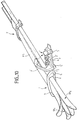
- FIG. 10 illustrates in perspective the possibility of transporting two pairs of skis and a PS surfboard, as it has been described in relation to FIG. 8. It has been assumed in this example that two pairs of ski carriers were used and mounted on two roof bars on a vehicle (not shown). In order not to overload the figure, only three ski-holding devices have been shown: two at the front, 1 and 1 ', and one at the rear. In addition, for a more complete illustration of the invention, the device 1 has been shown in the locked position, that is to say the arch 3 closed on the skis SK 1 and SK 2 and the PS board to be transported. The device 1 'has been shown in the unlocked position, hoop 3' open. We see in Figure 10 the elastic means 4 'disposed on the base 2'.
- ski-holding devices are made integral with the roof bars using flanges: flanges 5 and 5 ′ in the example illustrated surrounding the roof bar 6.
- the overall height of the elastic means is typically equal to 6 cm, the width of the tongues 41, 42 equal to 1 cm and their thickness equal to 2 at 3 mm.
- the elastic material of these tongues and of the tongue 45 will preferably be polyamide.
- the material of the adhesion pads will preferably be an elatomer
- FIGS. 11 to 14 A second embodiment of the ski carrier device according to the invention will now be described with reference to FIGS. 11 to 14.
- this embodiment differs essentially from the first mode by the arrangement and also, as will be emphasized below, by the specific configuration of the elastic means for holding the sporting goods to be transported : skis, surfboards or similar.
- the other components of the device according to this embodiment remain similar to those already described. There is therefore no need to re-detail them.
- FIG. 11 represents a partial section of the device, showing the configuration of the main elastic means, specific to this embodiment.
- the elastic means 7 comprise an element having the general shape of an "X".
- the two upper branches of this "X" are made integral with a horizontal plate 700 intended itself to be made integral with the underside of the arch 3 (horizontal region 30).
- the plate 700 can be forcibly inserted and held in grooves 301 and 302 formed in the wall of the hoop 3.
- any other fixing means within the reach of the skilled person, can be retained.
- the lower branches 73 and 74 of the "X" are open downwards.
- the assembly is completed by two lateral wings 75 and 76 in the shape of a "V" having undergone a rotation of 90 °, the points outwards.
- the branches of the "V" are placed symmetrically with respect to a horizontal axis ⁇ H passing through the center of the "X".
- the branches of the "X" and the side walls define a shape having the general shape of a rhombus.
- FIG. 12 schematically illustrates in side view, the whole of the ski carrier device according to the second alternative embodiment.
- the arch 3 is provided with an elastic means 7 and closes on the base 2, as before.
- the elastic means 7 are in principle sufficient to hold the objects to be transported in place, it is nonetheless true that certain categories of articles, such as surfboards pose specific problems. Indeed, surfboards are usually provided with prominent fasteners. If you are carrying two boards, they must be placed head to tail. Ausssi, it is necessary to raise them relative to the roof of the carrier vehicle and therefore also relative to the base 2. To do this, the device according to the invention is provided with auxiliary elastic means 8 secured to the base. These elastic means 8 can be fixed.
- they may consist of a ring of material with elastic properties 81 held by a support 80.
- the elastic means 7 is produced by extrusion and cutting to the desired length of a profile of material with elastic properties, the section of which has the shape illustrated in FIG. 7 or any equivalent shape.
- the equivalent form is understood to mean a form such that, as a function of the amplitude of crushing the elastic means 7, this exerts vertical reaction forces situated in at least two distinct ranges as a function of the cumulative thicknesses of objects to be transported also in two distinct ranges.
- the overall height of the profile, base of the elastic means 7, is of the order of 56 mm, its width 38 mm at the level of the bottom of the branches of the "X" and 30 mm at the level of the plate 700.
- the weight of such a profile is typically 690 g per meter.
- the material of the elastic means 7 will advantageously be an elastomer with a large shape memory, of the type known in the field under the acronym EPM.
- the grip palettes can be made of a similar material.
- the material of the auxiliary elastic means 8, at least the rings 81 will preferably be made from a more rigid material, for example polyethylene.
- the invention is not limited to the embodiments precisely described in relation in particular to FIGS. 1 to 14.
- the ski-holding devices were autonomous, in the sense that they are intended to be hung on roof bars or the like and can be dismantled, and although this provision is particularly advantageous since it allows the use of said bars for other uses, they can nevertheless form an integral part of roof bars used specifically for the transport of skis, surfboards or similar items.
- the number of elastic means 4 per device is not limited to two. Each device can be provided with a single elastic means or with three or more depending on the length of said device.
Landscapes
- Engineering & Computer Science (AREA)
- Mechanical Engineering (AREA)
- Fittings On The Vehicle Exterior For Carrying Loads, And Devices For Holding Or Mounting Articles (AREA)
- Warehouses Or Storage Devices (AREA)
Claims (14)
- Gepäckträger (1) für den Transport von länglichen Gegenständen, insbesondere von Skiern, Surfbrettern oder ähnlichen Gegenständen, der Bauart mit einem Sockel (2), der eine längliche, im wesentlichen ebene Innenfläche (21) aufweist, die zu einer ersten Richtung (Δ) parallel ist, und zumindest eine zu dieser senkrechte Wand (220), mit einem Bügel (3) und elastischen Mitteln (4), die zwischen dem Bügel (3) und dem Sockel (2) angeordnet sind, wobei der Bügel (3) und der Sockel (2) zumindest zwei unterschiedliche relative Positionen einnehmen können, wobei die eine, die als entriegelt bezeichnet sei, das Einsetzen zumindest eines zu transportierenden Gegenstands ins Innere des Gepäckträgers (1) ermöglicht, und in der anderen, die als verriegelt bezeichnet sei, die elastischen Mittel (4) die genannten zu transportierenden Gegenstände festhalten, indem sie eine Haltekraft ausüben, wobei die elastischen Mittel (4) zumindest eine erste und eine zweite, bestimmte Position zum Halten der zu transportierenden Gegenstände aufweisen, um den Transport von Gegenständen zu ermöglichen, deren kumulierte Dickenabmessungen sich in ersten und zweiten Dickenbereichen befinden, wobei zumindest ein elastisches Mittel (4), das auf dem genannten Sockel (2) gehalten ist, seitliche Elemente (41, 42) aufweist, die eine Feder bilden, sowie einen feststehenden Teil (43, 44), dadurch gekennzeichnet, daß jedes elastische Mittel (4), das auf dem Sockel (2) gehalten ist, einen translatorisch beweglichen Teil (40 430) aufweist, der mit den seitlichen Elementen (41, 42), die eine Feder bilden, fest verbunden ist, wobei der translatorisch bewegliche Teil (40, 430) in den feststehenden Teil (43, 44) eingesteckt ist, daß die seitlichen Elemente (41, 42), die eine Feder bilden, ein Zusammendrücken mit einer bestimmten Amplitude (l) des beweglichen Teils (40, 430) in einer im wesentlichen zu der ersten Richtung (Δ) senkrechten Richtung (Δ') ermöglichen, daß der feststehende Teil zwei mit dem Sockel (2) fest verbundene, einander gegenüberstehende Wände (43, 44) aufweist, die senkrecht zu der ersten Richtung (Δ) sind und V-förmig angeordnet sind, wobei die Spitze des V nach außen weist und die Wände einen Abstand voneinander aufweisen, so daß ein freier Durchgang mit einer bestimmten Breite (e) in der ersten Richtung (Δ) verbleibt, daß der genannte translatorisch bewegliche Teil eine Platte (430) und eine zentrale Lasche (40) aufweist, daß die seitlichen, eine Feder bildenden Elemente aus seitlichen, umgebogenen Laschen (41, 42) bestehen, daß die seitlichen (41, 42) und die mittlere Lasche (40) an ihrem unteren Endabschnitt mit einem Führungselement (400, 410, 420) versehen sind und an ihrem oberen Endabschnitt mit der genannten Platte (430) fest verbunden sind, daß die Breite der Laschen (40, 41, 42) kleiner ist als die festgelegte Breite (e) des frei verbleibenden Durchgangs, so daß das Einsetzen der Laschen zwischen die senkrechten Wände (43, 44) möglich ist, wobei die Führungselemente (400, 410, 420) Abmessungen aufweisen, die größer sind als die festgelegte Breite (e) und kleiner als der Abstand, der die Innenflächen der einander gegenüberstehenden Wände (43, 44) voneinander trennt, so daß ein Gleiten des beweglichen Teils (40, 430) an diesen Wänden entlang möglich ist und dessen Führung gewährleistet ist, daß eine der seitlichen Laschen (41, 42) eine Haltekraft parallel zu der genannten ersten Richtung (Δ) ausübt, wenn sich zumindest ein zu transportierender Gegenstand zwischen dieser Lasche und der zu dem Sockel (2) senkrechten Wand (220) befindet, und eine zu der ersten Richtung (Δ) senkrechte Haltekraft, wenn sich zumindest ein zu transportierender Gegenstand zwischen der Platte (430) und dem Bügel (3) befindet.
- Vorrichtung nach Anspruch 1, dadurch gekennzeichnet, daß die elastischen Mittel (4), zumindest die genannten seitlichen Elemente, die eine Feder (41, 42) bilden, aus Polyamid bestehen.
- Vorrichtung nach Anspruch 1, dadurch gekennzeichnet, daß zusätzliche elastische Mittel (45) vorhanden sind, die durch eine längliche Lasche gebildet werden, welche in ihrem mittleren Abschnitt an der Innenseite des Bügels (3) gehalten ist, wobei die Endabschnitte (451, 452) dieser Lasche (45) zum Inneren der Vorrichtung hin gekrümmt sind, um eine Feder zu bilden.
- Vorrichtung nach Anspruch 1, dadurch gekennzeichnet, daß der obere Teil der genannten Platte (430) und die Innenseite einer jeden Wand (220) des Sockels, die zu der genannten ersten Richtung (Δ) senkrecht ist, mit einem Haftplättchen (401, 222) versehen ist.
- Vorrichtung nach Anspruch 4, dadurch gekennzeichnet, daß das Haftplättchen aus einem Elastomermaterial besteht.
- Vorrichtung nach Anspruch 1, dadurch gekennzeichnet, daß eine (41) der seitlichen Laschen (41, 42) eine stärkere Krümmung als die andere seitliche Lasche (42) aufweist, so daß die Positionierung dieser Lasche (41) gegenüber einer senkrechten Wand (220) des Sockels (2) einen Aufnahmeraum bildet, der zum Transport von Gegenständen bestimmt ist, deren kumulierte Dicken in einem ersten Dickenbereich (l1) liegen, und daß die Positionierung der anderen Lasche (42) gegenüber dieser senkrechten Wand (220) des Sockels (2) einen Aufnahmeraum festlegt, der zum Transport von Gegenständen bestimmt ist, deren kumulierte Dicken in einem zweiten Dickenbereich (l2) liegen.
- Gepäckträger (1) für den Transport von länglichen Gegenständen, insbesondere von Skiern, Surfbrettern oder ähnlichen Gegenständen, der Bauart mit einem Sockel (2), der eine längliche, im wesentlichen ebene Innenfläche (21) aufweist, die zu einer ersten Richtung (Δ) parallel ist, und zumindest eine zu dieser senkrechte Wand (220), mit einem Bügel (3) und elastischen Mitteln (7), die zwischen dem Bügel (3) und dem Sockel (2) angeordnet sind, wobei der Bügel und der Sockel zumindest zwei unterschiedliche relative Positionen einnehmen können, wobei die eine, die als entriegelt bezeichnet sei, das Einsetzen zumindest eines zu transportierenden Gegenstands ins Innere des Gepäckträgers (1) ermöglicht, und in der anderen, die als verriegelt bezeichnet sei, die elastischen Mittel (7) die genannten zu transportierenden Gegenstände festhalten, indem sie eine Haltekraft ausüben, wobei die elastischen Mittel (7) zumindest eine erste und eine zweite, bestimmte Position zum Halten der zu transportierenden Gegenstände aufweisen, um den Transport von Gegenständen zu ermöglichen, deren kumulierte Dickenabmessungen sich in ersten und zweiten Dickenbereichen befinden, dadurch gekennzeichnet, daß er zumindest ein elastisches Mittel (7) aufweist, das mit dem Bügel (3) fest verbunden ist, und daß dieses elastische Mittel aus einer an dem Bügel (3) befestigten Platte (700) besteht, aus einem Element (71, 72, 73, 74) aus einem Material mit elastischen Eigenschaften, das im wesentlichen X-förmig ist, wobei die Endabschnitte von dessen oberen Armen (71, 72) an der genannten Platte (700) befestigt sind und die Endabschnitte von dessen unteren Armen (73, 74) frei sind, und aus seitlichen Verstärkungselementen (75, 76) dieses ersten, X-förmigen Elements, wobei die seitlichen Verstärkungselemente ebenfalls aus einem Material mit elastischen Eigenschaften bestehen, so daß auf die zu transportierenden Gegenstände eine in einem ersten Bereich enthaltene Haltekraft ausgeübt wird, wenn sich die kumulierten Dicken der Gegenstände innerhalb eines ersten Dickenbereichs befinden, wobei die genannte Haltekraft auf die Durchbiegung der unteren Arme (73, 74) des X-förmigen Elements zurückgeht, und wobei auf die zu transportierenden Gegenstände eine in einem zweiten Bereich enthaltene Haltekraft ausgeübt wird, wenn sich die kumulierten Dicken der Gegenstände innerhalb eines zweiten Dickenbereichs befinden, wobei die genannte Haltekraft auf die Verformung des X-förmigen Elements und der seitlichen Verstärkungselemente (75, 76) zurückgeht.
- Vorrichtung nach Anspruch 7, dadurch gekennzeichnet, daß die seitlichen Verstärkungselemente (75, 76) die Form eines "V" aufweisen, dessen Spitze in einer Richtung, die in einer zu der ersten Richtung (Δ) parallelen Ebene liegt, nach außen weist, so daß mit den Armen (71, 72, 73, 74) des X-förmigen Elements ein Viereck gebildet wird, welches verformbar ist, wenn zwischen die elastischen Mittel (7) und den Sockel (2) zu transportierende Gegenstände eingelegt werden, deren kumulierte Dicken sich in dem genannten zweiten Dickenbereich befinden.
- Vorrichtung nach einem der Ansprüche 7 oder 8, dadurch gekennzeichnet, daß das elastische Mittel (7) aus einem Elastomer besteht.
- Vorrichtung nach einem der Ansprüche 7 bis 9, dadurch gekennzeichnet, daß zusätzliche elastische Mittel (8) vorhanden sind, die an dem Sockel (2) befestigt sind.
- Vorrichtung nach Anspruch 10, dadurch gekennzeichnet, daß die genannten zusätzlichen elastischen Mittel (8) einen Ring (81) aus einem Material mit elastischen Eigenschaften aufweisen.
- Vorrichtung nach Anspruch 11, dadurch gekennzeichnet, daß das Material, aus dem der Ring (81) besteht, Polyethylen ist.
- Vorrichtung nach einem der Ansprüche 7 bis 9, dadurch gekennzeichnet, daß das genannte elastische Mittel (7) ein einstückiges Teil ist, das durch Extrusion hergestellt ist und aus einem Profil aus einem Material mit elastischen Eigenschaften geschnitten ist.
- Vorrichtung nach einem der Ansprüche 1 bis 13, gekennzeichnet durch Mittel zum Befestigen (5, 5', 221) an einer Dachschiene (6) eines Fahrzeugs.
Applications Claiming Priority (2)
| Application Number | Priority Date | Filing Date | Title |
|---|---|---|---|
| FR9400647 | 1994-01-21 | ||
| FR9400647A FR2715364B1 (fr) | 1994-01-21 | 1994-01-21 | Dispositif porte-objets polyvalent pour véhicules, notamment pour le transport de skis, planches de surf ou articles similaires. |
Publications (2)
| Publication Number | Publication Date |
|---|---|
| EP0664242A1 EP0664242A1 (de) | 1995-07-26 |
| EP0664242B1 true EP0664242B1 (de) | 1997-08-06 |
Family
ID=9459263
Family Applications (1)
| Application Number | Title | Priority Date | Filing Date |
|---|---|---|---|
| EP95400054A Expired - Lifetime EP0664242B1 (de) | 1994-01-21 | 1995-01-11 | Mehrzweck-Gepäckträger für Kraftfahrzeuge, insbesondere zum Transportieren von Skiern, Surfbrettern oder ähnlichem |
Country Status (7)
| Country | Link |
|---|---|
| US (1) | US5657915A (de) |
| EP (1) | EP0664242B1 (de) |
| JP (1) | JPH07223493A (de) |
| AT (1) | ATE156433T1 (de) |
| CA (1) | CA2140307A1 (de) |
| DE (1) | DE69500498T2 (de) |
| FR (1) | FR2715364B1 (de) |
Families Citing this family (11)
| Publication number | Priority date | Publication date | Assignee | Title |
|---|---|---|---|---|
| US5918488A (en) * | 1996-12-03 | 1999-07-06 | Deeter; Daniel Lee | Ladder lock |
| JP3148150B2 (ja) * | 1997-05-22 | 2001-03-19 | ラッキー工業株式会社 | ベビーホルダー兼用ウエストバッグ |
| IT245915Y1 (it) * | 1998-10-05 | 2002-03-26 | Fapa Spa | Portasci multiuso per autoveicoli. |
| US20030159956A1 (en) * | 2002-02-26 | 2003-08-28 | Woos Michael T. | Display backing card |
| EP1356851A1 (de) * | 2002-04-11 | 2003-10-29 | Bruno Rampinelli | Diebstahlsicherer Skihalter |
| US20060186157A1 (en) * | 2005-02-22 | 2006-08-24 | Dibble Richard J | Ski rack for pickup trucks |
| US20060289577A1 (en) * | 2005-06-23 | 2006-12-28 | Malone Larry D | Universal attachment system |
| US20070205240A1 (en) * | 2005-10-21 | 2007-09-06 | Jeff Castro | Vehicle top carriers |
| US20090159624A1 (en) * | 2007-12-20 | 2009-06-25 | Gm Global Technology Operations, Inc. | Roof rack features enabled by active materials |
| PL2842807T3 (pl) * | 2013-08-27 | 2018-10-31 | Thule Sweden Ab | Bagażnik rowerowy do pojazdu |
| US9649988B2 (en) * | 2014-12-30 | 2017-05-16 | Thule Sweden Ab | Ski carrier clamp |
Family Cites Families (6)
| Publication number | Priority date | Publication date | Assignee | Title |
|---|---|---|---|---|
| US3378182A (en) * | 1966-11-17 | 1968-04-16 | Karpak Company | Ski racks for carriers |
| US3610491A (en) * | 1970-04-20 | 1971-10-05 | Bott John Anthony | Automobile ski and luggage rack |
| US3726410A (en) * | 1971-06-11 | 1973-04-10 | Beatrice Foods Co | Ski clamping device |
| US4143799A (en) * | 1977-09-29 | 1979-03-13 | Dietlein Robert W | Ski rack, for vehicles |
| US4372470A (en) * | 1980-11-25 | 1983-02-08 | Bic Corporation | Car rack |
| US5115955A (en) * | 1990-01-24 | 1992-05-26 | 167848 Canada Inc. | Ski rack with adjustable retention post |
-
1994
- 1994-01-21 FR FR9400647A patent/FR2715364B1/fr not_active Expired - Fee Related
-
1995
- 1995-01-11 EP EP95400054A patent/EP0664242B1/de not_active Expired - Lifetime
- 1995-01-11 AT AT95400054T patent/ATE156433T1/de not_active IP Right Cessation
- 1995-01-11 DE DE69500498T patent/DE69500498T2/de not_active Expired - Fee Related
- 1995-01-16 CA CA002140307A patent/CA2140307A1/fr not_active Abandoned
- 1995-01-17 US US08/373,039 patent/US5657915A/en not_active Expired - Fee Related
- 1995-01-23 JP JP7027294A patent/JPH07223493A/ja not_active Withdrawn
Also Published As
| Publication number | Publication date |
|---|---|
| FR2715364B1 (fr) | 1996-04-12 |
| DE69500498T2 (de) | 1997-12-04 |
| DE69500498D1 (de) | 1997-09-11 |
| ATE156433T1 (de) | 1997-08-15 |
| FR2715364A1 (fr) | 1995-07-28 |
| CA2140307A1 (fr) | 1995-07-22 |
| EP0664242A1 (de) | 1995-07-26 |
| US5657915A (en) | 1997-08-19 |
| JPH07223493A (ja) | 1995-08-22 |
Similar Documents
| Publication | Publication Date | Title |
|---|---|---|
| EP0664242A1 (de) | Mehrzweck-Gepäckträger für Kraftfahrzeuge, insbesondere zum Transportieren von Skiern, Surfbrettern oder ähnlichem | |
| FR2794701A1 (fr) | Dispositif pour retenir et articuler une tablette arriere amovible de vehicule automobile | |
| EP1069632A1 (de) | Befestigungsanordnung einer Akkumulatorbatterie | |
| EP1321335B1 (de) | Teppich für Fahrzeug | |
| WO2014198721A1 (fr) | Dispositif perfectionné de support d'un panneau de coffre de véhicule automobile | |
| EP3825180B1 (de) | Trennwandvorrichtung für kühlfahrzeug | |
| CA2142060A1 (fr) | Dispositif porte-bagages pour vehicules | |
| FR2851528A1 (fr) | Tablette arriere pour vehicule automobile | |
| EP0572297B1 (de) | Haltervorrichtung für Fahrrollen und Koffer mit einer solchen Vorrichtung | |
| EP0216690A2 (de) | Vorrichtung zum Handhaben von blattförmigen Gegenständen | |
| FR3117465A1 (fr) | Colis de transport comprenant des moyens de calage en configuration repliée | |
| EP1076003B1 (de) | Vorrichtung zur Befestigung eines Gegenstandes, insbesondere einer Tasche, auf einem Motorradtank | |
| FR2915938A1 (fr) | Dispositif de support d'objets dans un coffre de vehicule automobile. | |
| EP3835133B1 (de) | Vorrichtung zum platzieren eines objektes auf einem fahrzeugdach | |
| EP0790014A1 (de) | Koffer | |
| WO1993024029A1 (fr) | Bagage souple ou rigide a roulettes comportant une poignee | |
| FR2732082A1 (fr) | Berceau de calage d'objets | |
| FR2754774A1 (fr) | Dispositif d'aide au chargement d'un coffre de vehicule automobile | |
| FR2909328A1 (fr) | Tablette destinee a etre accrochee a un volant automobile. | |
| FR2908092A1 (fr) | Dispositif de chargement et/ou dechargement d'un vehicule de transport, module de plancher d'un vehicule de transport et vehicule de transport | |
| FR2902724A1 (fr) | Agencement d'une tablette dans un caisson, notamment pour un vehicule automobile | |
| EP2756989B1 (de) | Halte- und/oder Verstauungssystem von Waren, insbesondere für Straßentransportfahrzeuge | |
| FR2757831A1 (fr) | Palette de manutention d'objets longitudinaux | |
| EP4071038A1 (de) | Vorrichtung zur befestigung von zubehörteilen an einem fahrrad | |
| FR3003180A1 (fr) | Dispositif de transport d’elements longilignes notamment des skis |
Legal Events
| Date | Code | Title | Description |
|---|---|---|---|
| PUAI | Public reference made under article 153(3) epc to a published international application that has entered the european phase |
Free format text: ORIGINAL CODE: 0009012 |
|
| AK | Designated contracting states |
Kind code of ref document: A1 Designated state(s): AT BE CH DE IT LI |
|
| 17P | Request for examination filed |
Effective date: 19950920 |
|
| 17Q | First examination report despatched |
Effective date: 19960515 |
|
| GRAG | Despatch of communication of intention to grant |
Free format text: ORIGINAL CODE: EPIDOS AGRA |
|
| GRAH | Despatch of communication of intention to grant a patent |
Free format text: ORIGINAL CODE: EPIDOS IGRA |
|
| GRAH | Despatch of communication of intention to grant a patent |
Free format text: ORIGINAL CODE: EPIDOS IGRA |
|
| GRAA | (expected) grant |
Free format text: ORIGINAL CODE: 0009210 |
|
| AK | Designated contracting states |
Kind code of ref document: B1 Designated state(s): AT BE CH DE IT LI |
|
| REF | Corresponds to: |
Ref document number: 156433 Country of ref document: AT Date of ref document: 19970815 Kind code of ref document: T |
|
| REG | Reference to a national code |
Ref country code: CH Ref legal event code: NV Representative=s name: IPTO S.A. Ref country code: CH Ref legal event code: EP |
|
| REF | Corresponds to: |
Ref document number: 69500498 Country of ref document: DE Date of ref document: 19970911 |
|
| ITF | It: translation for a ep patent filed | ||
| PGFP | Annual fee paid to national office [announced via postgrant information from national office to epo] |
Ref country code: AT Payment date: 19980112 Year of fee payment: 4 |
|
| PGFP | Annual fee paid to national office [announced via postgrant information from national office to epo] |
Ref country code: BE Payment date: 19980115 Year of fee payment: 4 |
|
| PGFP | Annual fee paid to national office [announced via postgrant information from national office to epo] |
Ref country code: DE Payment date: 19980128 Year of fee payment: 4 |
|
| PLBE | No opposition filed within time limit |
Free format text: ORIGINAL CODE: 0009261 |
|
| STAA | Information on the status of an ep patent application or granted ep patent |
Free format text: STATUS: NO OPPOSITION FILED WITHIN TIME LIMIT |
|
| 26N | No opposition filed | ||
| PG25 | Lapsed in a contracting state [announced via postgrant information from national office to epo] |
Ref country code: AT Free format text: LAPSE BECAUSE OF NON-PAYMENT OF DUE FEES Effective date: 19990111 |
|
| PG25 | Lapsed in a contracting state [announced via postgrant information from national office to epo] |
Ref country code: LI Free format text: LAPSE BECAUSE OF NON-PAYMENT OF DUE FEES Effective date: 19990131 Ref country code: CH Free format text: LAPSE BECAUSE OF NON-PAYMENT OF DUE FEES Effective date: 19990131 Ref country code: BE Free format text: LAPSE BECAUSE OF NON-PAYMENT OF DUE FEES Effective date: 19990131 |
|
| BERE | Be: lapsed |
Owner name: AUTOMAXI INDUSTRIES Effective date: 19990131 |
|
| REG | Reference to a national code |
Ref country code: CH Ref legal event code: PL |
|
| PG25 | Lapsed in a contracting state [announced via postgrant information from national office to epo] |
Ref country code: DE Free format text: LAPSE BECAUSE OF NON-PAYMENT OF DUE FEES Effective date: 19991103 |
|
| PG25 | Lapsed in a contracting state [announced via postgrant information from national office to epo] |
Ref country code: IT Free format text: LAPSE BECAUSE OF NON-PAYMENT OF DUE FEES;WARNING: LAPSES OF ITALIAN PATENTS WITH EFFECTIVE DATE BEFORE 2007 MAY HAVE OCCURRED AT ANY TIME BEFORE 2007. THE CORRECT EFFECTIVE DATE MAY BE DIFFERENT FROM THE ONE RECORDED. Effective date: 20050111 |